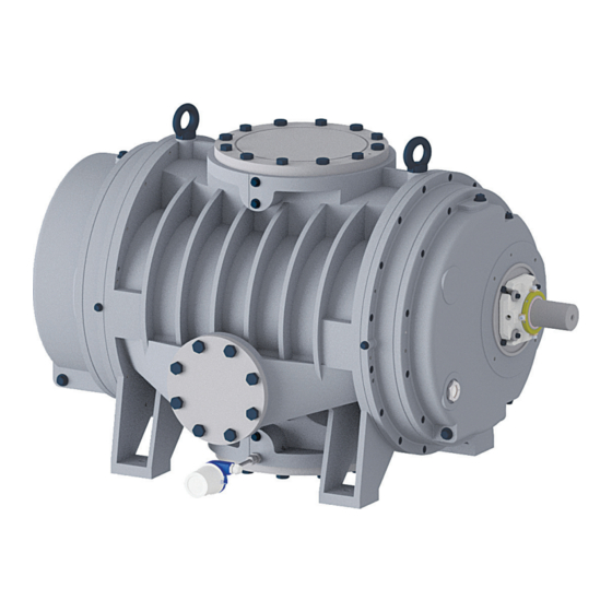
Pfeiffer Vacuum OKTA 8000 G ATEX Operating Instructions Manual
Roots pump
Hide thumbs
Also See for OKTA 8000 G ATEX:
- Operating instructions manual (56 pages) ,
- Operating instructions manual (58 pages)
Table of Contents
Advertisement
Quick Links
Advertisement
Table of Contents

Related Manuals for Pfeiffer Vacuum OKTA 8000 G ATEX


Summary of Contents for Pfeiffer Vacuum OKTA 8000 G ATEX
- Page 1 OPERATING INSTRUCTIONS Translation of the Original OKTA 8000 G ATEX Roots pump...
- Page 2 Dear Customer, Thank you for choosing a Pfeiffer Vacuum product. Your new roots pump should support you in your individual application with full performance and without malfunctions. The name Pfeiffer Vacuum stands for high-quality vacuum technology, a comprehensive and complete range of top-quality products and first-class service.
-
Page 3: Table Of Contents
Product usage limits Proper use Foreseeable improper use Personnel qualification 2.8.1 Ensuring personnel qualification 2.8.2 Personnel qualification for maintenance and repair 2.8.3 Advanced training with Pfeiffer Vacuum Product description Function Identifying the product Scope of delivery Transportation and Storage Transporting the vacuum pump... - Page 4 Shutting down for longer periods Recommissioning Recycling and disposal General disposal information Dispose of Okta roots pumps Malfunctions Service solutions by Pfeiffer Vacuum Spare parts 12.1 Ordering spare parts packs Accessories 13.1 Accessory information 13.2 Ordering accessories Technical data and dimensions 14.1 General...
- Page 5 List of tables List of tables Tbl. 1: Stickers on the product Tbl. 2: Abbreviations used Tbl. 3: ATEX designations Tbl. 4: Potential hazards Tbl. 5: Measures and safety equipment Tbl. 6: Permissible ambient conditions Tbl. 7: Permissible sealing media Tbl.
- Page 6 List of figures List of figures Fig. 1: Position of the stickers on the product Fig. 2: Assembly of Okta 8000 G ATEX Fig. 3: Functional diagram Okta G Fig. 4: Transporting the vacuum pump using a belt Fig. 5: Dismantle the fittings to vent the vacuum pump Fig.
-
Page 7: About This Manual
Keep the manual for future consultation. 1.1 Validity This operating instructions is a customer document of Pfeiffer Vacuum. The operating instructions de- scribe the functions of the named product and provide the most important information for the safe use of the device. The description is written in accordance with the valid directives. The information in this op- erating instructions refers to the product's current development status. -
Page 8: Pictographs
This section describes all the stickers on the product along with their meaning. Rating plate (example) The rating plate is located on the front side above the D-35641 Asslar sight glass Mod.: Okta 8000 G ATEX Mod.-No.: PP G80 ... Ser. -No.: 1234567895 max. 2250 1/min Oil: P3 21.0 l S(N): max. -
Page 9: Abbreviations
About this manual Fig. 1: Position of the stickers on the product 1 Direction of rotation arrow (cast in pump housing) D1 lubricant note 2 Hot surface warning sign Fill lubricant note 3 Rating plate 1.3.4 Abbreviations Abbreviation Explanation Okta "G" Gas circulation cooled roots pump Safety Integrity Level in accordance with safety standard DIN EN 61508 Equipment Protection Level... -
Page 10: Safety
Safety 2 Safety 2.1 General safety information The following 4 risk levels and 1 information level are taken into account in this document. DANGER Immediately pending danger Indicates an immediately pending danger that will result in death or serious injury if not observed. ►... - Page 11 Safety WARNING Risk of serious injury from swinging, toppling or falling objects During transport, there is a risk of crushing and impact on swinging, toppling or falling objects. There is a risk of injuries to limbs, up to and including bone fractures and head injuries. ►...
- Page 12 Safety CAUTION Danger of injury from moving parts After a power failure or a standstill as a result of overheating, the motor restarts automatically. There is a risk of injury to fingers and hands if they enter the operating range of rotating parts. ►...
- Page 13 Safety CAUTION Danger of burns on hot surfaces Depending on the operating and ambient conditions, the surface temperature of the vacuum pump can increase to above 70 °C. ► Provide suitable touch protection. CAUTION Health hazard from increased noise emission Remaining in the close proximity of the vacuum pump for a sustained period of time may cause hear- ing damage.
-
Page 14: Safety Precautions
Safety WARNING Health hazard and environmental damage from toxic contaminated lubricant Toxic process media can cause lubricant contamination. When changing the lubricant, there is a health hazard due to contact with poisonous substances. Illegal disposal of toxic substances causes environmental damage. ►... -
Page 15: Labeling Of The Vacuum Pump
Safety ● With ATEX-certified motor: II 3/3G Ex h IIC T3 Gc X +5 °C ≤ Ta ≤ +40 °C ● A part of the product does not comply with the ATEX Directive, and cannot therefore be used in potentially explosive areas (e.g. roots pump without ATEX-certified motor): II 3/-G Ex h IIC T3 Gc X +5 °C ≤... -
Page 16: Potential Hazards
Safety Classifica- Description tion Special operating conditions must be observed! Special conditions and notes in the operating instructions apply. Permissible ambient temperature for operation of the vacuum pump prescribed on the rating plate. Tbl. 3: ATEX designations 2.4.2 Potential hazards The ignition hazard assessment for the roots pumps in the ATEX series was performed in accordance with the harmonized standard ISO 80079-36 (Non-electrical equipment for explosive atmospheres - Ba- sic method and requirements). -
Page 17: Product Usage Limits
► To protect the lubricant, use sealing gas if media with a high boiling point or corrosive media (e.g. solvents) are being pumped. ► Adhere to the installation, commissioning, operating, and maintenance instructions. ► Use only accessory parts recommended by Pfeiffer Vacuum. ► Use the vacuum pump to convey potentially explosive atmospheres in accordance with the label- ing. -
Page 18: Personnel Qualification
● Using the vacuum pump in strong electrical, magnetic, or electromagnetic fields ● Use of the vacuum pump with open vacuum and/or fore-vacuum flange open to the atmosphere ● Using lubricants not specified by Pfeiffer Vacuum ● Using pipes to lift the vacuum pump ●... -
Page 19: Personnel Qualification For Maintenance And Repair
─ Customer with Pfeiffer Vacuum service training ─ Pfeiffer Vacuum service technician 2.8.3 Advanced training with Pfeiffer Vacuum For optimal and trouble-free use of this product, Pfeiffer Vacuum offers a comprehensive range of courses and technical trainings. For more information, please contact Pfeiffer Vacuum technical training. -
Page 20: Product Description
Lubrication is limited to the two bearing and gear chambers which are arranged separately from the suction chambers. Roots pumps of the ATEX series are equipped with a thermometer. Fig. 2: Assembly of Okta 8000 G ATEX 1 Vacuum flange Sight glass (2×) 2 Measurement connection, vacuum flange Axial face seal 3 Lubricant filling plug (2×) -
Page 21: Identifying The Product
3.2 Identifying the product To ensure for a clear identification of the product when communicating with Pfeiffer Vacuum, always keep all of the information on the rating plate to hand. The following information is shown on the rating plate: ●... -
Page 22: Transportation And Storage
● Fill the gear and bearing chambers with lubricant only once the final installation posi- tion is reached. Preparations for transport Pfeiffer Vacuum recommends keeping the transport packaging and original protective cov- General information regarding safe transport 1. Observe weight specified on the rating plate. -
Page 23: Storing The Vacuum Pump
4.2 Storing the vacuum pump The roots pumps do not have any corrosion protection on the inside. Storage Pfeiffer Vacuum recommends storing the products in their original transport packaging. Procedure 1. Close both connection flanges. 2. Check that the other openings, such as sealing gas connections or measurement connections are correctly closed. -
Page 24: Installation
Installation 5 Installation 5.1 Preparatory work WARNING Risk of crushing from rotating parts Fingers and hands may be caught by rotating pistons within the connection flange. This results in se- vere injuries. ► Keep limbs out of the reach of the roots pump. Filling the nitrogen The vacuum pump is filled with nitrogen to protect against corrosion, therefore the suction chamber has a slight over pressure (200 hPa) upon delivery... -
Page 25: Installing The Vacuum Pump
► Please refer to rating plate of the vacuum pump for type and quantity of intended lubricant. – Only the lubricant used during initial installation is permissible. ► Contact Pfeiffer Vacuum if you want to use another type of lubricant. Permissible lubricants ●... -
Page 26: Fill The Sealing Medium For The Axial Face Seal
Installation Required tools ● Open-end wrench, WAF 17 ● Calibrated torque wrench (tightening factor ≤ 2.5) max. min. Fig. 6: Filling with lubricant 1 Filler screw, gear side O-ring 2 O-ring Sight glass, gear side 3 Filler screw, motor side Sight glass, bearing chamber Procedure 1. -
Page 27: Connecting The Vacuum Side
Installation Sealing medium Viscosity [mm Pump lubricant Shell Morlina S2 B 32 32 at T=40 °C Anderol 495 28 at T=40 °C Tbl. 7: Permissible sealing media Required consumables ● Sealing medium container including fittings ● Sealing medium Fig. 7: Sealing agent container for axial face seal 1 Filler port Sealing ring housing... -
Page 28: Tbl. 8: Maximum Permissible Forces And Torques On The Connection Flange
Installation NOTICE Property damage from intake of solid particles During commissioning, there is a risk of damage to the suction chamber from dirt from the system or the pipes. ► Use a suitable protective strainer ("start-up strainer") in the intake flange. ►... -
Page 29: Connecting The Fore-Vacuum Side
(optional). The dimensioning of the gas cooler and the cold gas circulation pipe is the responsibility of the operat- ing company. As an alternative, Pfeiffer Vacuum can assist you with the authorization of the dimension- ing. -
Page 30: Connecting The Cooling Water Supply
Installation Fig. 9: Roots pump with tubular gas cooler 1 Vacuum flange Cooling water connection, inlet 2 Cooling gas connection Fore-vacuum connection 3 Fore-vacuum flange Gas cooler 4 Measurement connection Cold gas circulation pipe 5 Cooling water connection, outlet Temperature monitoring 6 Measurement connection Procedure 1. -
Page 31: Tbl. 9: Requirements On The Cooling Water Composition
Installation Additional monitoring devices to be provided on site: ● Cooling water control valve ● Flow indicator, optional ● Cooling water pressure monitor, optional Parameter Cooling water Appearance ● filtered ● mechanically clear ● visually clear ● no turbidity ● no sediment ●... -
Page 32: Setting And Checking The Temperature Monitoring
Installation Connecting the cooling water supply 1. Make sure that the outlet is unpressurized and that a visual check can be made of the flow rate. – The best method is the free outflow of cooling water via a funnel. –... -
Page 33: Arrange A Signal Evaluation For The Thermometer
Installation Fig. 11: Temperature monitoring 1 Locking screw of the measurement connection Installation dimension X 2 Fore-vacuum flange Thermometer Checking the installation of the thermometer ► Check the installation dimension "X" and tighten the clamping screw if necessary. – X = 239.3 mm 5.9.2 Arrange a signal evaluation for the thermometer A restart following "zero potential"... -
Page 34: Establishing Mains Connection
► Route the mains connection in accordance with locally applicable provisions. ► Always provide a suitable mains fuse to protect the motor and supply cable in the event of a fault. – Pfeiffer Vacuum recommends the circuit breaker type "K" with slow tripping characteristic. NOTICE Motor damage from overheating Limited motor fan cooling capacity, caused by low speeds, causes the motor to overheat. -
Page 35: 2Checking The Direction Of Rotation
Installation Fig. 12: Delta connection for low voltage The 3 phases are connected in series, and their connection points connected to the mains. The voltage per phase is equal to the mains voltage, while the mains current is √3 times the phase current. The del- ta connection is marked with the ∆... -
Page 36: 3Connecting The Ptc Thermistor Tripping Unit
Installation 5.10.3 Connecting the PTC thermistor tripping unit Pfeiffer Vacuum recommends connecting motors with PTC in the stator winding to a PTC resistor trip- ping device for protection against overload. Tripping units store the shut-down. F1 - F3 AC 220 ... 240 V T1...T3... -
Page 37: Tbl. 12: Permissible Deviation Between Motor Shaft And Pump Shaft
Installation Minimum requirements Motor and coupling to be selected in accordance with the scope of validity prescribed by European Directive 2014/34/EU. The roots pump meets the requirements of ATEX Category 3/3G (inside/outside). ● In the event of potentially explosive atmospheres outside, ensure when selecting the motor and coupling that their identification conforms at least with the identification of the roots pump. -
Page 38: Operation
Operation 6 Operation 6.1 Putting the vacuum pump into operation Before switching on 1. Check the lubricant levels on both sight glasses. 2. Compare the voltage and frequency specifications on the motor rating plate with the available mains voltage and frequency. 3. Make sure that the suction chamber is free from all foreign matters. 4. -
Page 39: Switching On The Vacuum Pump
Operation 6.3 Switching on the vacuum pump WARNING Danger of poisoning due to toxic process media escaping from the exhaust pipe During operation with no exhaust line, the vacuum pump allows exhaust gases and vapors to escape freely into the air. There is a risk of injury and fatality due to poisoning in processes with toxic process media. -
Page 40: Adjusting The Sealing Gas Amount
Operation 6.4 Adjusting the sealing gas amount WARNING Risk of injury from reactive, potentially explosive or other hazardous gas/air mixtures Uncontrolled gas inlet of air or gases containing oxygen provides ideal conditions for the formation of unexpected explosive gas/air mixtures in the vacuum system. This results in severe injuries. ►... -
Page 41: Fig. 17: Position Of The Vibration Sensors
Operation Boundary conditions of the vibration measurement The boundary conditions of the vibration measurement (including operating conditions, measurement parameters etc.) and the vibration measurement equipment (incl. vibration sensors) must meet the requirements of guidelines VDI 3836 and VDI 3832 and standards DIN ISO 10816-1 and DIN ISO 10816-3. -
Page 42: Condition Monitoring Of The Vacuum Pump
● Assessment of the root-mean-square-value of the vibration acceleration and / or the maximum value amount of the vibration acceleration in a band. Evaluating the vibration spectrum Due to the early and clearer diagnosis for bearing damage, Pfeiffer Vacuum recommends using the envelope curve spectrum. 42/62... -
Page 43: Monitoring The Motor Condition
Operation Bearing Bearing damage frequency Okta 8000 G ATEX Fixed bearing Cage rotation frequency (0.43 × n) Hz Rollover frequency of an irregularity on the outer ring (9.04 × n) Hz Rollover frequency of an irregularity on the inner ring (11.96 ×... -
Page 44: Switching Off And Venting The Vacuum Pump
Operation 6.6 Switching off and venting the vacuum pump WARNING Risk of crushing on rotating parts when reaching into the open flange The pistons continue to run in the vacuum after switching off the motor, and can trap fingers and hands within their reach. ►... -
Page 45: Maintenance
► Keep limbs out of the reach of the roots pump. NOTICE Damage from incorrect maintenance work Unprofessional work on the vacuum pump will lead to damage for which Pfeiffer Vacuum accepts no liability. ► Ensure that only the following categories of persons are authorized to perform servicing tasks: –... -
Page 46: Checklist For Inspection And Maintenance
You can carry out maintenance work of Maintenance Level 1 by yourself. We recommend Pfeiffer Vacuum Service for carrying out maintenance work of Maintenance Level 2 and Maintenance Level 3 (revision). If the required intervals listed below are exceeded, or if mainte- nance work is carried out improperly, no warranty or liability claims are accepted on the part of Pfeiffer Vacuum. -
Page 47: Changing The Lubricant
The usable life may deviate from the reference value specified depending on thermic and chemical loads, or due to penetrating process media in gear and bearing chambers. Safety data sheets You can obtain the safety data sheets for lubricants from Pfeiffer Vacuum on request, or from the Pfeiffer Vacuum Download Center. -
Page 48: Cleaning The Suction Chamber
Drain screw 3 Drain screw Draining the lubricant Consult with Pfeiffer Vacuum Service about shorter maintenance intervals for extreme loads or impure processes. 1. Shut down the vacuum pump and allow it to cool if necessary. 2. Vent the vacuum pump to atmospheric pressure via the intake side. - Page 49 Maintenance ● the friction heat inside the roots pump increases ● the power consumption of the roots pump increases ● the pistons jam Procedure 1. Dismantle the pipes from the vacuum and fore-vacuum connections. 2. Clean the suction chamber using suitable brushes and cleaning agents. 3.
-
Page 50: Decommissioning
The useful life of the lubricant is limited (max. 2 years). Prior to recommissioning, carry out the follow- ing operations following inactivity of 2 years or more: ► Observe the maintenance instructions – consult Pfeiffer Vacuum where necessary. ► Change the lubricant. -
Page 51: Recycling And Disposal
– Fluoroelastomers (FKM) – Potentially contaminated components that come into contact with media 9.2 Dispose of Okta roots pumps Pfeiffer Vacuum roots pumps from the Okta series contain materials that you must recycle. 1. Fully drain the lubricant. 2. Dismantle the motor. -
Page 52: Malfunctions
► Wear personal protective equipment if necessary. NOTICE Danger of property damage from improper maintenance Unprofessional work on the vacuum pump will lead to damage for which Pfeiffer Vacuum accepts no liability. ► We recommend taking advantage of our service training offering. -
Page 53: Tbl. 18: Troubleshooting
● Switch off the vacuum pump immedi- ing or gear wheels ately. ● Contact Pfeiffer Vacuum Service. ● Damage to motor ● Switch off the vacuum pump immedi- bearing ately. ● Change the motor. ● If necessary, contact Pfeiffer Vacuum Service. Tbl. 18: Troubleshooting 53/62... -
Page 54: Service Solutions By Pfeiffer Vacuum
We are always focused on perfecting our core competence – servicing of vacuum components. Once you have purchased a product from Pfeiffer Vacuum, our service is far from over. This is often exactly where service begins. Obviously, in proven Pfeiffer Vacuum quality. - Page 55 Service solutions by Pfeiffer Vacuum 5. Prepare the product for transport in accordance with the provisions in the contamination declaration. a) Neutralize the product with nitrogen or dry air. b) Seal all openings with blind flanges, so that they are airtight.
-
Page 56: Spare Parts
Spare parts 12 Spare parts 12.1 Ordering spare parts packs Observe the following instructions when ordering spare parts: ► Have the vacuum pump part number, and any other necessary details from the rating plate, to hand when ordering spare parts. ► Install original spare parts only. 56/62... -
Page 57: Accessories
Accessories 13 Accessories View the line of accessories for Pfeiffer Vacuum roots pumps online at pfeiffer-vacuum.de. 13.1 Accessory information Sealing gas device The use of sealing gas at the bearing points protects the lubricant from contamination by the ingress of process media and flushing fluid into the bearing and oil chambers. -
Page 58: Technical Data And Dimensions
Technical data and dimensions 14 Technical data and dimensions 14.1 General Basis for the technical data of Pfeiffer Vacuum roots pumps ● Specifications according to PNEUROP committee PN5 ● ISO 21360-1: 2016 “Vacuum technology - Standard methods for measuring vacuum-pump per- formance - General description”... -
Page 59: Dimensions
G 1/2'' Ø Ø M20 (8×) 1385 DN 300 PN10 Dichtrille/sealing groove Innen-/inner Außen-/outer DN 300 PN10 Tiefe/depth 3.4 DN 150 PN10 Ø M20 (12×) 482.6 482.6 Ø M20 (12x) Ø Fig. 19: Okta 8000 G ATEX Dimensions in mm 59/62... -
Page 60: Declaration Of Conformity
DIN ISO 21360-1: 2016 ISO 21360-2: 2012 DIN EN ISO 13732-1: 2008 The authorized representative for the compilation of technical documents is Mr. Wolf- gang Bremer, Pfeiffer Vacuum GmbH, Berliner Straße 43, 35614 Asslar, Germany. Signature: Pfeiffer Vacuum GmbH Berliner Straße 43... - Page 61 61/62...
- Page 62 Notizen / Notes:...
Need help?
Do you have a question about the OKTA 8000 G ATEX and is the answer not in the manual?
Questions and answers