Table of Contents
Advertisement
Quick Links
Advertisement
Table of Contents

Subscribe to Our Youtube Channel
Related Manuals for Pfeiffer Vacuum MVP 015-4 DC


Summary of Contents for Pfeiffer Vacuum MVP 015-4 DC
- Page 1 OPERATING INSTRUCTIONS Translation of the Original MVP 015-4 DC Diaphragm Pump...
-
Page 2: Telegram Example
These operating instructions describe all models and variants of your product. Note that your product may not be equipped with all features described in this document. Pfeiffer Vacuum constantly adapts its products to the latest state of the art without prior notice. Please take into account that online operating instructions can deviate from the printed operating instructions supplied with your product. -
Page 3: Table Of Contents
5.5.2 Inputs 5.5.3 Outputs 5.5.4 RS-485 interface allocation 5.5.5 Cross-linked via the RS-485 connection 5.5.6 Connection options via interface RS-485 Pfeiffer Vacuum protocol for RS-485 interface 5.6.1 Telegram frame 5.6.2 Telegram description 5.6.3 Telegram example 1 5.6.4 Telegram example 2 5.6.5 Data types used... - Page 4 Checklist for inspection and maintenance Replace the diaphragms and valves Decommissioning Decommissioning the vacuum pump for longer periods Disposing of the vacuum pump Errors Service solutions from Pfeiffer Vacuum Spare parts 11.1 Ordering spare parts packs Accessories Technical data and dimensions 13.1 General 13.2 Technical data...
- Page 5 Behavior and meaning of the LED of the electronic drive unit Tbl. 15: Maintenance intervals for diaphragm pumps Tbl. 16: Troubleshooting on diaphragm pumps Tbl. 17: Spare parts packs for the MVP 015-4 DC Tbl. 18: MVP 015-4 DC accessories Tbl. 19: Conversion table: Pressure units Tbl. 20: Conversion table: Units for gas throughput Tbl.
- Page 6 Replacing the diaphragms and valves on the MVP 015-4 Fig. 12: Spare parts for the MVP 015-4 DC Fig. 13: Dimension diagram of MVP 015-4 DC | standard design Fig. 14: Dimension diagram of MVP 015-4 DC | pumping station design 6/48...
-
Page 7: About This Manual
These instructions apply to diaphragm pumps of the DC series: ● MVP 015-4 DC as standard version ● MVP 015-4 DC in the version for integration in a pumping station (without base plate) 1.2 Target group This operating instructions are aimed at all persons performing the following activities on the product: ●... -
Page 8: Stickers On The Product
Meaning in this document Diaphragm Pump Direct Current Display Control Unit (Pfeiffer Vacuum display and control unit). Nominal diameter as size description Rotation speed value of a vacuum pump (frequency, in rpm or Hz) Handheld Programming Unit. Aid for control and monitoring of pump parameters... -
Page 9: Tbl. 2: Abbreviations Used In This Document
About this manual Abbreviation Meaning in this document Illuminating diode Earthed conductor (protective earth) [P:xxx] Electronic drive unit control parameters. Printed in bold as three-digit number in square brackets. Frequently displayed in conjunction with a short description. Example: [P:312] software version Temperature (in °C), property abbreviation of the vacuum pump Turbopump electronic drive unit (turbo controller) Voltage supply (turbo power supply) -
Page 10: Safety
Safety 2 Safety 2.1 General safety instructions This document includes the following four risk levels and one information level. DANGER Imminent danger Indicates a hazardous situation which, if not avoided, will result in death or serious injury. ► Instructions on avoiding the hazardous situation WARNING Possibly imminent danger Indicates a hazardous situation which, if not avoided, could result in death or serious injury. -
Page 11: Safety Precautions
Safety Risks during operation WARNING Danger of poisoning due to toxic process media escaping from the exhaust pipe During operation with no exhaust line, the vacuum pump allows exhaust gases and vapors to escape freely into the air. There is a risk of injury and fatality due to poisoning in processes with toxic process media. -
Page 12: Product Usage Limits
IEC 61010 and IEC 60950. Pfeiffer Vacuum recommends that only original power supply packs are used. Pfeiffer Vacuum guarantees compliance with the requirements of European and North American guidelines only in this case. - Page 13 ● Connection to devices with exposed live parts ● Connecting to sockets without earthing contact ● Using lubricants not specified by Pfeiffer Vacuum ● Using pipes to lift the vacuum pump ● Use of accessories or spare parts that are not listed in these instructions ●...
-
Page 14: Product Description
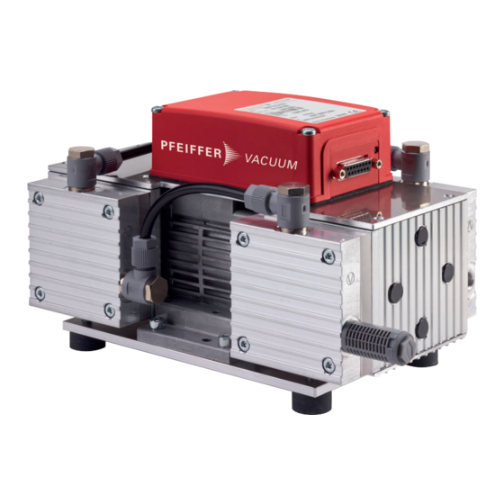
● Blind plug on the vacuum connection 3.3 Function The MVP 015-4 DC series diaphragm pump is a dry compressing vacuum pump with 4 pumping stages. The vacuum pump is a positive displacement pump with a periodic change in suction chamber size, produced by the movement of the diaphragm. - Page 15 Product description Fig. 4: Design of the MVP 015-4 DC A Diaphragm head 1 Plug-in connector B Diaphragm head 2 C Diaphragm head 3 Hose connection D Diaphragm head 4 Base plate 1 Exhaust with silencer Grounding screw 2 Vacuum connection, 1/8'' thread...
-
Page 16: Transportation And Storage
4 Transportation and Storage 4.1 Transporting the vacuum pump Pfeiffer Vacuum recommends keeping the transport packaging and original protective cov- In order to prevent dirt and foreign matter from entering the pump interior, it is important that the protec- tive cap is kept on the vacuum connection during transport. -
Page 17: Installation
Using the shortest possible vacuum connection lines with large nominal diameter prevents pressure losses. Condensate separator Pfeiffer Vacuum recommends the installation of a condensate separator in case vapors are formed from moisture during evacuation. Procedure 1. Remove the locking cap from the vacuum connection. -
Page 18: Connecting The Exhaust Side
Installation 5.3 Connecting the exhaust side CAUTION Danger of injury from bursting as a result of high pressure in the exhaust line Faulty or inadequate exhaust pipes lead to dangerous situations, e.g., increased exhaust pressure. There is a danger of bursting. Injuries caused by flying fragments, the escaping of high pressure, and damage to the unit cannot be excluded. -
Page 19: Pin Assignment Of The D-Sub Socket, 15-Pin
Installation Fig. 6: Pin assignment of the D-Sub socket, 15-pin Function Description, factory setting +24 VDC input Voltage supply for drive and interface DI access request V+: Control via DIs, --> GND/open: Control unlocked V+: Rotation speed setting mode, --> GND/open: no rotation speed set- ting mode Only valid for vacuum pumps with a solenoid valve;... -
Page 20: Connection Example: Mvp 015-4 - Dcu/Tps With Connecting Cable
Installation Fig. 7: Connection example: MVP 015-4 – DCU/TPS with connecting cable PM 061 350 -T HiPace Fig. 8: Connection example: MVP 015-4 – HiPace/DCU/TPS with connecting cable PE 100 013 -T 20/48... -
Page 21: Voltage Supply
Installation 5.5.1 Voltage supply 24 V DC input: The voltage supply is carried out using a connecting cable from the Pfeiffer Vacuum accessories or using a cable provided by the customer. ● Pin 1: +24 V DC ● Pin 15: Earth (GND) 24 V DC output / pin 7: Inputs 2 to 6 are activated if they are connected to pin 7 (active high) with +24 VDC. -
Page 22: Rs-485 Interface Allocation
► Connect only suitable devices to the bus system. The connection of a Pfeiffer Vacuum display and control panel (DCU or HPU) or an external PC are each possible on pin 13 and pin 14. -
Page 23: Connection Options Via Interface Rs-485
Fig. 10: Connection options via interface RS-485 Connecting Pfeiffer Vacuum display and control panels or PC At interface RS-485, one external control panel can be connected in each case. 1. Use the respective connection cable supplied with the control panel or from the range of accesso- ries. -
Page 24: Pfeiffer Vacuum Protocol For Rs-485 Interface
Installation 5.6 Pfeiffer Vacuum protocol for RS-485 interface 5.6.1 Telegram frame The telegram frame of the Pfeiffer Vacuum protocol contains only ASCII code characters [32; 127], the exception being the end character of the telegram C. . Basically, a master (e.g. a PC) sends a telegram, which is answered by a slave (e.g. -
Page 25: Data Types Used
Installation --> ASCII 5.6.4 Telegram example 2 Control command Switch on the pumping station (parameter [P:010], device address Slave: "042" --> ASCII Control command understood Switch on the pumping station (parameter [P:010], device address Slave: "042" --> ASCII 5.6.5 Data types used Data type Description Length l1 –... -
Page 26: Operation
Important settings and function-related variables are factory-programmed into the vacuum pump elec- tronic drive unit as parameters. Each parameter has a three-digit number and a description. Parameter- driven operation and control is supported via Pfeiffer Vacuum displays and control units, or externally via RS-485 using Pfeiffer Vacuum protocol. -
Page 27: Switching On The Vacuum Pump
All variables of the vacuum pump relevant for the function are stored as parameters in the electronic drive unit. Each parameter has a three-digit number and a description. Parameters can be used via Pfeiffer Vacuum display and control panels or via RS-485 with the Pfeiffer Vacuum protocol. Conventions Parameters are printed in bold as three-digit numbers in square brackets. -
Page 28: Parameter Overview
Brief description of the parameters Functions Function description of the parameters Data type Type of formatting of the parameter for the use with the Pfeiffer Vacuum protocol Access type R (read): Read access; W (write): Write access Unit Physical unit of the described variable min. -
Page 29: Status Requests
Operation Display Designations Functions Data Unit min. max. type cess fault type stored CtrlViaInt Operation of 1 = remote the interface 2 = RS-485 4 = PV.can 32 = Keys on the front panel 255 = Interface selection IntSelLckd Interface se- 0 = off lection locked 1 = on... -
Page 30: Reference Value Inputs
Operation 6.4.5 Reference value inputs Display Designations Functions Data Unit min. max. can be type cess fault stored type SpdSVal Setpoint in speed-con- Set rotation trol operation speed in x.x% of the nominal rotation speed StdbySVal Rotational speed set- 66.7 point in standby opera- tion RS485Adr RS-485 Interface ad-... -
Page 31: Speed Actuator Operation
3. Check the set rotation speed (parameter [P:308] or [P:397]). 6.4.8 Standby mode Pfeiffer Vacuum recommends standby mode for during process and production stops. With active stand-by mode, the electronic drive unit reduces the speed of the vacuum pump in the range of 30 to 100% of the nominal speed. -
Page 32: Temperature Monitoring
Operation Display Activity Meaning 100% active ● No errors ● Vacuum pump "ON" ● Target speed reached ● Defect 50% active, 10, Hz Tbl. 14: Behavior and meaning of the LED of the electronic drive unit 6.5.2 Temperature monitoring In event of impermissibly high pump temperature (> 75 °C), the motor speed is reduced to a nominal rotation speed (n = 1500 min ) in order to avoid the vacuum pump from overheating. -
Page 33: Maintenance
If the required intervals listed below are exceeded, or if maintenance work is carried out im- properly, no warranty or liability claims are accepted on the part of Pfeiffer Vacuum. This also applies if original spare parts are not used. -
Page 34: Replace The Diaphragms And Valves
Depending on the operating conditions, the required maintenance intervals can be shorter than the reference values specified in the table. Please consult Pfeiffer Vacuum if necessary. Valves and diaphragms are wear parts. At the latest when the reached pressure values decrease, the suction chamber, the diaphragms as well as the valves should be cleaned and checked for cracks. - Page 35 Maintenance A – D Fig. 11: Replacing the diaphragms and valves on the MVP 015-4 A – D Diaphragm heads Intermediate plate Banjo bolt Diaphragms Cylinder screws Spacer disks Valves Silencer Sealing ring (only on diaphragm head A) Required tools ●...
-
Page 36: Decommissioning
Decommissioning 8 Decommissioning 8.1 Decommissioning the vacuum pump for longer periods Observe the following notes before shutting down the vacuum pump for a longer period of time: Brief procedure after condensate forming 1. Allow the vacuum pump to run on for a few more minutes with the vacuum connection open. 2. -
Page 37: Errors
► Wear personal protective equipment if necessary. NOTICE Danger of property damage from improper maintenance Unprofessional work on the vacuum pump will lead to damage for which Pfeiffer Vacuum accepts no liability. ► We recommend taking advantage of our service training offering. -
Page 38: Tbl. 16: Troubleshooting On Diaphragm Pumps
● If necessary, check or replace missing the silencer. ● Valves dirty or defective ● If necessary, clean or replace the valves and diaphragms. ● Connection rod or motor ● Contact Pfeiffer Vacuum Service. bearing defective Tbl. 16: Troubleshooting on diaphragm pumps 38/48... -
Page 39: Service Solutions From Pfeiffer Vacuum
We are consistently striving to perfect our core competence, service for vacuum components. And our service is far from over once you’ve purchased a product from Pfeiffer Vacuum. It often enough really just begins then. In proven Pfeiffer Vacuum quality, of course. - Page 40 Service solutions from Pfeiffer Vacuum 5. Prepare the product for transport in accordance with the details in the declaration of contamination. a) Neutralize the product with nitrogen or dry air. b) Close all openings with airtight blank flanges. c) Seal the product in appropriate protective film.
-
Page 41: Spare Parts
PU E22 031 -T 1, 2, 4 (complete) Silencer P 0920 567 E P 0920 567 E Interhead connection PK 050 272 -T PK 050 272 -T complete (3x) Tbl. 17: Spare parts packs for the MVP 015-4 DC 41/48... -
Page 42: Accessories
Accessories 12 Accessories Accessories for MVP 015-4 DC order number Hose Connection DN 6 x 400 mm with G 1/8" and G 1/4” Straight Fitting P 0920 739 E Hose Connection DN 6 x 1000 mm with G 1/8" and G 1/4” Straight Fitting P 0920 817 E Hose DN 6;... -
Page 43: Technical Data And Dimensions
Technical data and dimensions 13 Technical data and dimensions 13.1 General Basis for the technical data of Pfeiffer Vacuum diaphragm pumps: ● Specifications according to PNEUROP committee PN5 ● ISO 21360:2012: “Vacuum technology - Standard methods for measuring vacuum-pump perform- ance - General description”... -
Page 44: Substances In Contact With The Media
Straight compression coupling on the intake flange CuZn nickel-plated Suction hose Polyethylene Exhaust, silencer Polyamide Tbl. 22: Materials that touch the process media inside the diaphragm pump 13.4 Dimensions G1/8" G1/8" Fig. 13: Dimension diagram of MVP 015-4 DC | standard design 44/48... -
Page 45: Dimension Diagram Of Mvp 015-4 Dc | Pumping Station Design
Technical data and dimensions G1/8" G1/8" 5.5 (4x) Ø Fig. 14: Dimension diagram of MVP 015-4 DC | pumping station design 45/48... -
Page 46: Declaration Of Conformity
Restriction of the use of certain hazardous substances 2011/65/EU The authorized representative for the compilation of technical documents is Mr. Sebas- tian Oberbeck, Pfeiffer Vacuum GmbH, Berliner Straße 43, 35614 Aßlar, Germany. MVP 015-4 DC Harmonized standards and applied national standards and specifications:... - Page 47 47/48...
Need help?
Do you have a question about the MVP 015-4 DC and is the answer not in the manual?
Questions and answers