Pfeiffer Vacuum Pascal Series Maintenance Instruction
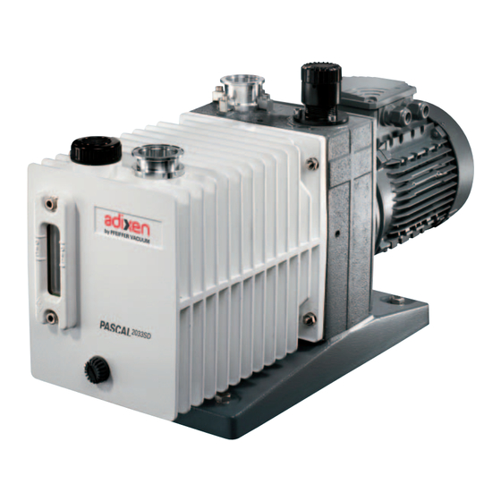
Rotary vane pump
Hide thumbs
Also See for Pascal Series:
- Operating instructions manual (71 pages) ,
- Maintenance instructions manual (45 pages) ,
- Operating instructions manual (49 pages)

Related Manuals for Pfeiffer Vacuum Pascal Series


Summary of Contents for Pfeiffer Vacuum Pascal Series
- Page 1 MAINTENANCE INSTRUCTIONS MAINTENANCE INSTRUCTIONS Translation of the original instructions Translation of the original instructions PASCAL SERIES PASCAL SERIES Rotary vane pumps 33 to 63 m Rotary vane pumps 33 to 63 m /h /h...
-
Page 2: Table Of Contents
Rotary vane pumps Dear customer, This Maintenance instructions is intended for customers of the Pfeiffer Vacuum Company. It describes the product maintenance operations which can be performed by the user on the product concerned. This documentation must be used together with the operating manual for the product of the same name. - Page 3 MANUAL P/N: 105527M EDITION: 01 - October 2015 Indicates a potentially hazardous situation which, if not avoided, could result in property damage. Indicates a potentially hazardous situation which, if not avoided, could result in moderate or minor injury. It may also be used to alert against unsafe practices.
-
Page 4: Safety Instructions For Maintenance
Vacuum original spare parts, delivered by Pfeiffer Vacuum, containing i.e. all its components and sub-assemblies. This obligation will not cover the shipping cost to a Pfeiffer Vacuum taking back facility. Whenever you return the product to an repair service center, please make sure you follow the Service procedure and fill in the declaration of contamination found on our website. -
Page 5: Tools And Consumable Products
Tools and consumable products Special precautions Read the safety instructions at the beginning of the maintenance chapter. Before disassembling the pump, drain it (see Operating instructions). All the seals and faulty parts should be replaced: provide a seal kit or an overhaul kit. - Page 6 Specific tools This kit contains the usefull tools to disassemble and reassemble the shaft seals in the different flanges and flanged stators. Tools kit DESCRIPTION For all pump models, kit including: 065192 Mounting mandrel 19.5 mm 065089 Protective sleeve 065088 Washer 073331 Coupling adjustment tool...
-
Page 7: Disassembling The Pump
Disassembling the pump Removing pump from Study the general precautions listed on Maintenance chapter page 37. system The following steps are necessary to protect the pump as far as possible from the effects of corrosion: • Flush pump with a neutral gas (dry nitrogen) during half an hour to prevent toxic or corrosive gases accumulating in the pump. - Page 8 Disassembling the pump (cont’d) Removing the oil case Install the pump vertically on a work bench using a hoist. (see page N-2) Remove the nuts (4) then (5) and remove the oil casing (A) and its O-ring (3). The presence of an oil casing flat gasket may cause case (A) and frame (B) to stick together due to aging.
- Page 9 Disassembling the pump (cont’d) Disassembling the pumping module (see page N-4) Remove the screws (18), (17) then (34), (33) and the cover(s) (16), (32). Removing the exhaust valve Remove the exhaust valves (13), (30) and their springs (15) (31) and for 63C1 model, cover (16) and (32) the washer (14).
- Page 10 Disassembling inlet nipple (9) Remove 4 screws (4), (7) then (3), (6) and remove clamps (2) and (5). (see page N-10) Remove nipple (9) and its O-ring (8). Remove the metallic filter (31) and clean it. Disassembling exhaust nipple (3) Remove the protection (1).
-
Page 11: Cleaning Components
Cleaning components Cleaning metal Solvents are required to clean components. components Standard precautions should be taken in compliance with the manufacturer's instructions. After use in mineral or synthetic oil, clean the metal components with a mineral products based solvent such as AXAREL , CARECLEAN , PREMACLEAN NAPHTESOL... -
Page 12: Replacement Of Shaft Seals
Replacement of shaft seals Specific tools • Specific extraction tool. • Specific assembly mandrel. • A support plate (or washer). Recommended tools • A flat screwdriver. • A hammer. Extracting a shaft With the flange flat: the seal is extracted using washer a screwdriver, resting on the plate (or washer) so seal from its housing... - Page 13 Direction of assembly They are fitted using the assembly mandrel according to the direction of assembly below: of shaft seals HP stator BP stator HP rotor BP rotor Frame Double lip seal Lip seal Rings Seal holder Rear flange Flange To install the flanges, use protective sleeve and oil it Assembly the before mounting flange (or wrap end of shaft with...
-
Page 14: Reassembling The Pump
Reassembling the pump Component • All parts must be dry so that no solvent remains, particularly in blind holes • Check that the lubrication holes are not blocked. preparation • Oil used for lubricate pump parts must be the same as oil used for pump operation. Before reassembly •... - Page 15 Reassembling the pump (cont’d) Oil inlet tube (1) reassembly When positioning the oil inlet tube (1), make sure that screw is properly centered in the (C2 Model) centering hole, the collector located at the upper part of the tube must line up under the oil fill port in the oil casing.
-
Page 16: Start-Up After Pump Disassembly
Start-up after pump disassembly or oil change (cont’d) Start-up after pump disassembly or oil change Using noise limiter The principle of the noise limiter is described in the Operating instructions. It is adjusted at the factory when the pump is checked and need only to be readjusted after: - pump disassembly-reassembly operations, - changing the oil type (not all oils are miscible in the same proportions with... -
Page 17: Service
Fill out the «Service Request/Product return» form and send it to your local Pfeiffer in the Pfeiffer Vacuum Service contact. Vacuum Service Include the confirmation on the service request from Pfeiffer Vacuum with your Center shipment. Fill out the declaration of contamination and include it in the shipment (mandatory!). - Page 18 Composants de maintenance / Maintenance components / Unterhaltung Teile Plan de montage cuve et bâti ..........Oil casing and central housing assembly drawing ....Gesamtplan Ölbehälter und Pumpenträger ........N-2 Nomenclature cuve et bâti ..........Oil casing and central housing part list ........Nomenklatur Ölbehälter und Pumpenträger ......... N-3 Plan du bloc fonctionnel (D) ..........Pumping module drawing (D) ..........
-
Page 19: Plan De Montage Cuve Et Bâti
Plan de montage cuve et bâti Detailed next pages Oil casing and central housing assembly drawing Ölbehälter und Pumpenträger Gesamtplan C2 model C1 Model Clamping Rep. Part torque (N·m) Nut H M8 SD Model 4/10/16 Nut H M10 Stud M8-28 Stud M10-30 Stud M8-20 Stud M10-25... - Page 20 Nomenclature cuve et bâti / Oil casing and central housing part list / Ölbehälter und Pumpenträger Nomenklatur REF. REF. DÉSIGNATION SPECIFICATION BENENNUNG DÉSIGNATION SPECIFICATION BENENNUNG Bestell. Bestell. 22 Flasque moteur 50/60 Hz 50/60 Hz motor flange 50/60 Hz Motorflansch 054419 Cuve Oil casing Ölbehälter...
-
Page 21: Plan Du Bloc Fonctionnel (D)
Plan bloc fonctionnel (D) Pumping module drawing (D) Gesamtplan Pumpenblock (D) Clamping torque Rep. Part (N·m) Nut HM8 Nut HM 10 Stud M8-105 Stud M10-137 18/34 Screw CHC M6-45... - Page 22 Nomenclature bloc fonctionnel (D) / Pumping module part list (D) / Pumpenblock Nomenklatur (D) REF. REF. DÉSIGNATION SPECIFICATION BENENNUNG DÉSIGNATION SPECIFICATION BENENNUNG Bestell. Bestell. 18 Vis CHC M6-45 Screw CHC M6-45 Schraube CHC M6-45 Ecrou H M8 Nut H M8 Mutter H M8 Ecrou H M10 Nut H M10...
-
Page 23: Plan Système De Lubrification Pompe À Huile (E)
Plan système de lubrification pompe à huile (E) Oil pump system drawing (E) Ölpumpsystem Gesamtplan (E) Clamping torque Rep. Part (N·m) Screw CHC M6-12 Screw CHC M5-8 Screw CHC M8-40 Screw CHC M6-20... -
Page 24: Nomenclature Système De Lubrification
Nomenclature système de lubrification pompe à huile (E) / Oil pump system part list (E) / Ölpumpsystem Nomenklatur (E) Types/model REF. DÉSIGNATION SPECIFICATION BENENNUNG Bestell. Nr Tube de prise d'huile Oil admission tube Öleinlass 054268 Tube de prise d'huile Oil admission tube Öleinlass 065509 Tube de prise d'huile... -
Page 25: Plan De Détail Cuve (A)
Plan de détail cuve (A) Clamping torque Oil casing detail drawing (A) Rep. Part (N·m) Einzelplan Ölbehälter (A) Screw CHC M8-20 Screw CHC M6-20 C1 Model C2 Model SD Model... - Page 26 Nomenclature cuve (A) / Oil casing part list (A) / Nomenklatur Ölbehälter (A) REF. REF. DÉSIGNATION SPECIFICATION BENENNUNG DÉSIGNATION SPECIFICATION BENENNUNG Bestell. Bestell. 41 Joint torique c 2,70 - d 16,90 O-ring c 2.70 - d 16.90 Dichtung c 2,70 - d 16,90 Protecteur plat Flat protector Blindflansche...
-
Page 27: Plan De Détail Bâti (B)
Plan de détail bâti (B) Central housing detail drawing (B) Clamping torque Einzelplan Pumpenträger (B) Rep. Part (N·m) Screw CHC M6-20 Screw CHC M6-12... - Page 28 Nomenclature bâti (B) / Central housing part list (B) / Pumpenträger Nomenklatur (B) REF. REF. DÉSIGNATION SPECIFICATION BENENNUNG DÉSIGNATION SPECIFICATION BENENNUNG Bestell. Bestell. 31 Filtre d'aspiration Inlet filter Inlate filter 054202 Bâti Central Housing Pumpenträger 054117S Bâti Central Housing Pumpenträger 054405S 31 Filtre d'aspiration Inlet filter...
-
Page 29: Plan Ensemble Motorisation (M)
Plan ensemble motorisation (M) Motor assembly drawing (M) Motor Gesamtplan (M) Clamping torque Rep. Part (N·m) Screw Hc M6 x 8.8 (s.steel) -
Page 30: Nomenclature Ensemble Motorisation (M)
Nomenclature ensemble motorisation (M) / Motor assembly part list (M) / Motor Nomenklatur (M) Types/model REF. DÉSIGNATION SPECIFICATION BENENNUNG Bestell. Nr Anneau élastique denté Elastic coupling Elastische Zahnscheibe Anneau élastique denté Elastic coupling Elastische Zahnscheibe Manchon moteur Motor coupling Motorkupplung 054116 Manchon moteur Motor coupling... - Page 31 VACUUM SOLUTIONS FROM A SINGLE SOURCE VACUUM SOLUTIONS FROM A SINGLE SOURCE Pfeiffer Vacuum stands for innovative and custom vacuum solutions worldwide, Pfeiffer Vacuum stands for innovative and custom vacuum solutions worldwide, technological perfection, competent advice and reliable service. technological perfection, competent advice and reliable service.
Need help?
Do you have a question about the Pascal Series and is the answer not in the manual?
Questions and answers