
Subscribe to Our Youtube Channel
Related Manuals for Pfeiffer Vacuum Pascal 2033 SD


Summary of Contents for Pfeiffer Vacuum Pascal 2033 SD
- Page 1 Pascal 2033-2063 Series Rotary vane pumps Operating instructions Operating instructions...
- Page 2 Welcome Rotary vane pumps 2033 - 2063 SD-C1-C2 Dear customer, You have just bought an adixen rotary vane pump. We would like to thank you and are proud to count you among our customers. This product is a result of experience acquired over many years by adixen Vacuum Products in the design of rotary vane pumps.
- Page 3 This product complies with the requirements of European Directives. listed in the Declaration of Conformity contained in page 56 of this manual. Copyright/Intellectual property: The use of adixen products are subject to copyright and intellectual property rights in force in any jurisdiction. All rights reserved.
-
Page 4: Table Of Contents
MANUEL P/N: 105527 EDITION : 04 - July 2012 Translated from original version Contents Introduction Presentation of the product range ............2033 - 2063 m /h rotary vane pumps - SD, C1, C2 Pascal series ... Operating principle of the rotary vane pump ......... Oil - Noise limiter - Antisudback ............ -
Page 5: Presentation Of The Product Range
Presentation of the product range A wide range Oil seal rotary vane pumps are used in all vacuum technology applications. Specific solutions adapted to They can be used on their own to achieve a maximum vacuum of 10 Torr (10 mbar). -
Page 6: 2033 - 2063 M 3 /H Rotary Vane Pumps - Sd, C1, C2 Pascal Series
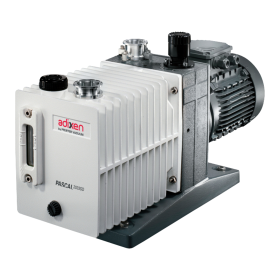
2033 - 2063 m /h rotary vane pumps. SD, C1, C2 Pascal series The 33 to 63m /h pump models, have following main characteristics: – A direct drive motor making them very compact. – An anti-suckback system ensures the tightness of the pump during accidental or voluntary shutdowns. -
Page 7: Operating Principle Of The Rotary Vane Pump
Operating principle of the rotary vane pump Single-stage This is a volumetric pump, with a functional part composed of: • A hollow cylindrical stator with inlet and exhaust valves. rotary vane pump • A rotor mounted eccentrically inside the stator for pumping. •... - Page 8 Two-stage To improve the backing pressure and flowrate at low pressure, two stages are connected in series. The second is similar to the first both structurally and operationally. rotary vane pump The gases pulled in by the first stage (low pressure) are transferred to the second stage (high pressure) and discharged through the high pressure (HP) valve.
-
Page 9: Oil - Noise Limiter - Antisudback
Oil - Noise limiter - Antisuckback Oil has several important functions in the pump: – It lubricates mechanical components (bearings, seals, rotor, vanes, etc.). – It makes moving parts relatively tight by limiting internal leakage. – It carries away the heat produced by the compressed gases. Choosing the right oil Not all oils produce the same ultimate pressure in a given pump. - Page 10 Anti-noise Parallel to the oil flow, there is a small orifice in the venturi tube (5), which reduces the noise level at ultimate pressure. Because of the negative pressure created at the end of the venturi tube (5), gases are entrained into the moving layers of oil dampening pump noise, allowing the fluid to become more compressible.The added gases will affect the ultimate pressure, therefore, a compromise between sound level and ultimate pressure has to be reached as follows:...
- Page 11 Gas ballast (cont’d) Using the gas ballast increases the ultimate pressure of the pump as well as the temperature. The gas ballast control, located on the frame cannot be used to set the gas injection flow rate. When the gas ballast control is open, the pump is not tight when stopped. To guarantee this tightness, install an automatic gas ballast.
-
Page 12: Technical Characteristics
Technical characteristics For industry: Characteristics Unit 2033 SD 2063 SD SD Series Frequency Number of stages Nominal rotation speed 1500 1800 1500 1800 Nominal flow rate 23.3 42.4 Flow rate Pneurop method 18.8 Torr/mbar 3.75.10 / < 5.10 3.75.10 / < 5.10 Partial ultimate pressure with A120 oil 5.10... - Page 13 Technical characteristics (cont’d) Corrosive applications: Characteristics Unit 2033 C2 2063 C2 C2 Series Frequency Number of stages Nominal rotation speed 1500 1800 1500 1800 Nominal flow rate 23.3 42.4 Flow rate Pneurop method 18.8 Partial ultimate pressure with A120 oil Torr/mbar/Pa 3.75.10 / 5.10...
-
Page 14: Pump Dimensions
Pump dimensions SD Series 2033 motors Dimensions Weight (mm/inch) (kg/lb) 21.7 114449 10.6 47.8 18.2 119997 10.5 40.1 16.4 119998 10.5 36.2 C1 Series C2 Series 2063 motors Dimensions Weight (mm/inch) (kg/lb) 29.8 114450 11.8 65.7 119979 12.6 57.3 119980 12.6 57.3 Dimensions en mm... -
Page 15: Accessories
Accessories Name SD C1 C2 Part number Location Fonctions 104887 OME 40 S Oil mist • Separates oil droplets and particles contained in 068785 Exhaust OME 40 C1 eliminator exhaust gases emitted by the pump. 068492 OME 40 C2 • Separates oil droplets and particles contained in High pressure oil mist exhaust gases emitted by the pump when pump eliminator... -
Page 16: Safety Instructions Concerning The Installation And Operation
Safety instructions concerning the installation and operation Before switching on the equipment, the user must read all of the start-up and operation sections of this manual and observe the safety instructions listed in this manual. Unpacking We took care to provide you with a clean appliance. To keep it in this condition, unpack it only in its final place of use. - Page 17 Storage (cont’d) • After 3 months storage without oil, factors such as temperature, degree of humidity, salt air, etc. may cause the deterioration of the pump components, particularly the hardening of O-rings and the "sticking" of lip seals on shafts and the gumming of oil. In this state, a pump may have operational problems, particularly oil leaks.
-
Page 18: Table Of Recommended Oils
Table of recommended oils Recommended oils In the vane pumps, we recommend to use only the adixen oils in the table below: Vapor Total Flash point/ Viscosity mm²/ pressure ultimate self ignition Oils Characteristics and applications SD C1 C2 Density s (cst) at 25°C pressure*... - Page 19 Recommended oils (cont’d) However, the following Mineral oil: replacement fluids can be used: ELF MOVIXA PV 100, TURBELF SA 100, BP CS 100 (BP registered trademark) SHELL VITREA 100 (SHELL registered trademark) TOTAL CORTIS PV 100 (TOTAL registered trademark) INLAND 19, INLAND 20 (INLAND registered trademark) MR 200 (MATSUMURA registered trademark) Mineral-based synthetic oils: ELF BARELF F 100, ELF BARELF C 68 (ELF registered trademark)
- Page 20 If necessary, carry out the special preparation procedure for the pump (see page 41), then: - remove the filling cap (A). - fill with oil until: - the oil is between the maximum and minimum levels (SD, C2 Series), - the oil reaches the middle of the sight glass (C1 Series).
- Page 21 EN – 20...
-
Page 22: Mechanical Connections
Mechanical connections For a given application, pump performance, vacuum characteristics, temperature and reliability depend on the following: • assembly conditions (accessory, filter...) and mechanical connections, • used oil, • maintenance frequency and quality. For the assembly of the vacuum circuit, provide the accessories required for maintenance: isolation valves, purges, etc. - Page 23 Inlet and exhaust fitting (cont’d) At exhaust: When pumping on corrosive, aggressives or flammable gases, the gas can cause injury or death. In these cases, - connect the exhaust of the pump to an exhaust stack or an evacuation duct. - connect a relief valve or rupture disc directly on the pump.
- Page 24 Purge and indicator Serie Item Description Connection connections 1/8’ NPT Gas ballast purge 1/8’ NPT Oil casing purge Oil pressure sensor M 10 X 1 connection * 1/8’ NPT Purge - Bubbler Oil casing temperature M 12 X 1 sensor connection * * Sensors are customer supplied.
-
Page 25: Electrical Connections
Electrical connections Ensure that the product is connected to an electrical installation: - in compliance with the local and national safety requirements, - equipped with electrical protection (fuses, circuit breaker, …) which has a suitable earth (ground) point, properly connected. Our products are designed to comply with current EEC regulations. - Page 26 Differential circuit breaker. In case of insulation defect, for personnel protection you must install on the main power supply a type B differential circuit breaker GFI (or RCD) of 30 mA minimum. This equipment protection device is compatible with type T.T electrical network.
- Page 27 Electrical connections of three-phase motors (cont’d) Terminal box with 9 wires and 9 terminals Different types of motors are available in accordance to the major international standards UL, CSA, VDE. The three phase motors are compatible with the following voltages: Motor voltage range - Capacity limits Motor Country...
-
Page 28: External Motor Protection, Electrical Protection
External motor protection, electrical protection Installation protection with circuit breaker. The user must supply the pump from facilities equipped with amain circuit breaker, curve D (IEC 60947-2), in accordance with local regulations and with a minimum amp. interrupting current of 10 KAIC. This protection device should be in close proximity to the pump (no further than 7m (25 ft) within line of sight of the pump). - Page 29 EN – 28...
-
Page 30: Operation
Operation Preliminary precautions The performance and operational safety of this product are guaranteed provided it is used normally in the operating conditions defined in this manual. It is the customer’s task to: - train operators to use the product if they do not speak the language the manual is written in, - ensure operators know the safe practices to apply when using the product. -
Page 31: Before Starting Up The Pump
Operation (cont’d) Before starting-up the pump Check periodically that the pipes and accessories (i.e. oil mist eliminator) connected at exhaust are not clogged and that the purge is running. In certain cases, when the pump is started up in cold ambient conditions, or with slightly contaminated oil, the current after start-up may remain high until the oil in the pump is heated up. -
Page 32: Operation Of Gas Ballast
Operation of gas ballast Regeneration of In a pump stored with the same oil for a long time, condensed vapors may contaminate the oil bath and affect performance. This is also the case after pumping vapors and pump oil when the oil appears cloudy or discolored through the sight glass. •... - Page 33 Pumping condensable vapors (cont’d) Vapor pumping procedure • Isolate the pump from the system and increase the pump temperature, 30 minutes with gas ballast (see page 31). • Start pumping and check the oil level: - The oil level drops, oil is being lost, add oil in the pump. - The oil level rises;...
-
Page 34: Purges For Pumping Condensable, Corrosive And Hazardous Gases
Purges for pumping condensable, corrosive, and hazardous gases C1 and C2 Series Purges The use of vane pumps may result in pumping gases or vapors which are flammable or that could contaminate the oil. In this case, these products must be diluted using purges supplied with dry gases, such as nitrogen to avoid undesirable reactions. - Page 35 Purges for pumping condensable, corrosive, and hazardous gases (cont’d) Purge and sensor setting table Setting Corresponding absolute Neutral gas flow (l/h) Pressure (bars) Model Item Description T (°C) pressure (bar) (indicative value) mini average maxi Starting Operating Problem 2033 1200 1500 2000 C1/C2...
-
Page 36: Oxygen Pumping
Oxygen pumping In certain applications, mixtures containing oxygen at different concentrations, or even pure oxygen, are used. Oils of mineral origin are combustible. Exposure to pure oxygen at high temperatures may cause them to self-ignite. In addition, they are highly oxidized during pumping and quickly lose their lubricating properties. -
Page 37: Recovery Of Oil (High Pressure Pumping And Cycling)
Recovery of oil (high pressure and cycling) When the pump operates at high pressure, the oil heats up, becomes more fluid and is flushed out of the functional block by the gas stream. Oil losses at the exhaust are increased. If the pump only operates for a very short time at high pressure, the lubricating oil For intermittent is replaced when the pump returns to low pressure. -
Page 38: Safety Instructions For Maintenance
Safety instructions for maintenance General precautions For normal operation, the maintenance of 2033-2063 m /h series pumps only require regular oil changes (see page 41). Maintenance must be performed by a skilled maintenance operator trained in the relevant health and safety aspects (EMC, electrical hazards, chemical pollution, etc.). -
Page 39: Troubleshooting And Corrective Actions
Troubleshooting and corrective actions Incidents Causes Corrective actions The pump is not running • Incorrect motor power supply. Check the power supply. • Temperature too low. Reheat the pump and its oil. • Gumming of seals after prolonged Disassemble the motor and try to turn storage. - Page 40 Incidents Causes Corrective actions The vacuum pump does not produce Ultimate pressure obtained: a few 7.5 x10 Torr (10 mbar) a vacuum (continued) • Gas ballast knob open (or supplied Close the gas ballast or stop the dry air with dry nitrogen C1,C2 Series). supply.
- Page 41 Troubleshooting and corrective actions (cont’d) Incidents Causes Corrective actions Pump too hot (cont’ed) • Oil contaminated. Drain, flush and refill with clean oil. • Pump not prepared for the oil used Check pump configuration or type of oil. or oil unsuitable. Considerable oil losses •...
-
Page 42: Maintenance Frequency
Maintenance Maintenance Frequency Operating conditions frequency 6 months “normal”, 24h per day 1 year “normal”, < 12h per day 1 year “normal”, 24h per day Pump 2 years “normal”, < 12h par day The frequency values are minimum values for «normal» operating conditions: pressure <... -
Page 43: Draining
Maintenance (cont’d) Draining The draining operation places the contaminated pumping circuit in communication with the outside atmosphere. Take all necessary steps to ensure personal safety: wear gloves, protective glasses. The pump must be drained when hot and after the oil case has been vented to atmospheric pressure. -
Page 44: Start-Up After Pump Disassembly Or Oil Change
Change of type of oil (cont’d) Incompatible oils This is the case when, for example, a mineral oil is replaced by a synthetic oil (e.g. A120 by A113). Synthetic oils are considered to be incompatible with each other for practical reasons: they are expensive. -
Page 45: Tools And Consumable Products
Tools and consumable products Special precautions Read the safety instructions at the beginning of the maintenance chapter. Before disassembling the pump, drain it (see page 42). All the seals and faulty parts should be replaced: provide a seal kit or a maintenance kit. - Page 46 Specific tools This kit contains the usefull tools to disassemble and reassemble the shaft seals in the different flanges and flanged stators. Tools kit DESCRIPTION For all pump models, kit including: 065192 Mounting mandrel 19.5 mm 065089 Protective sleeve 065088 Washer 073331 Coupling adjustment tool...
-
Page 47: Disassembling The Pump
Disassembling the pump Removing pump from Study the general precautions listed on Maintenance chapter page 37. system The following steps are necessary to protect the pump as far as possible from the effects of corrosion: • Flush pump with a neutral gas (dry nitrogen) during half an hour to prevent toxic or corrosive gases accumulating in the pump. - Page 48 Removing the oil case Install the pump vertically on a work bench using a hoist. (see page N-2) Remove the nuts (4) then (5) and remove the oil casing (A) and its O-ring (3). The presence of an oil casing flat gasket may cause case (A) and frame (B) to stick together due to aging.
- Page 49 Disassembling the pump (cont’d) Disassembling the pumping module (see page N-4) Remove the screws (18), (17) then (34), (33) and the cover(s) (16), (32). Removing the exhaust valve cover (16) and (32) Remove the exhaust valves (13), (30) and their springs (15) (31) and for 63C1 model, the washer (14).
-
Page 50: Cleaning Components
Disassembling inlet nipple (9) Remove 4 screws (4), (7) then (3), (6) and remove clamps (2) and (5). (see page N-10) Remove nipple (9) and its O-ring (8). Remove the metallic filter (31) and clean it. Disassembling exhaust nipple (3) Remove the protection (1). -
Page 51: Replacement Of All Shaft Seals
Replacement of shaft seals Specific tools • Specific extraction tool. • Specific assembly mandrel. • A support plate (or washer). Recommended tools • A flat screwdriver. • A hammer. Extracting a shaft With the flange flat: the seal is extracted using washer a screwdriver, resting on the plate (or washer) so seal from its housing... - Page 52 Direction of assembly They are fitted using the assembly mandrel according to the direction of assembly below: of shaft seals HP stator BP stator HP rotor BP rotor Frame Double lip seal Lip seal Rings Seal holder Rear flange Flange To install the flanges, use protective sleeve and oil it Assembly the before mounting flange (or wrap end of shaft with...
-
Page 53: Reassembling The Pump
Reassembling the pump Component • All parts must be dry so that no solvent remains, particularly in blind holes • Check that the lubrication holes are not blocked. preparation • Oil used for lubricate pump parts must be the same as oil used for pump operation. Before reassembly •... - Page 54 Oil inlet tube (1) reassembly When positioning the oil inlet tube (1), make sure that screw is properly centered in the (C2 Model) centering hole, the collector located at the upper part of the tube must line up under the oil fill port in the oil casing. Air inlet tube (7) reassembly Install the spring (6) and screw the air inlet tube (7) and unscrew it of the number of turns given, when disassembling (usually 3 or 4 turns) (see page 48).
-
Page 55: Declaration Of Contamination
You wish to return an adixen product for maintenance. The equipment will be dismantled and possibly cleaned by a technician from our service centre. Pfeiffer Vacuum requires this form to be completed to preclude the potential health risk to its service personnel that can occur when receiving, disassembling, or repairing potentially contaminated products.. - Page 56 EN – 55...
-
Page 57: Declaration Of Conformity
EN – 56... - Page 58 Composants de maintenance / Maintenance components / Unterhaltung Teile Plan de montage cuve et bâti ..........Oil casing and central housing assembly drawing ....Gesamtplan Ölbehälter und Pumpenträger ........N-2 Nomenclature cuve et bâti ..........Oil casing and central housing part list ........Nomenklatur Ölbehälter und Pumpenträger ......... N-3 Plan du bloc fonctionnel (D) ..........Pumping module drawing (D) ..........
-
Page 59: Plan De Montage Cuve Et Bâti
Plan de montage cuve et bâti Oil casing and central housing assembly drawing Ölbehälter und Pumpenträger Gesamtplan C2 model C1 Model Detailed next pages SD Model Clamping torque Rep. Part (DaN.m) Nut H M8 4/9/16 Nut H M10 Stud M8-28 ZN10C Stud M8-28 SS Stud M10-30 Stud M8-20... - Page 60 Nomenclature cuve et bâti / Oil casing and central housing part list / Ölbehälter und Pumpenträger Nomenklatur REF. REF. DÉSIGNATION SPECIFICATION BENENNUNG DÉSIGNATION SPECIFICATION BENENNUNG Bestell. Bestell. Cuve Oil casing Ölbehälter see N-9 22 Flasque moteur 50/60 Hz 50/60 Hz motor flange 50/60 Hz Motorflansch 054419 M Motor tri...
-
Page 61: Plan Du Bloc Fonctionnel (D)
Plan bloc fonctionnel (D) Pumping module drawing (D) Gesamtplan Pumpenblock (D) Clamping torque Rep. Part (DaN.m) Stud M8-105 Stud M10-137 18/34 Screw FHC M6-45 0.65... -
Page 62: Nomenclature
Nomenclature bloc fonctionnel (D) / Pumping module part list (D) / Pumpenblock Nomenklatur (D) REF. REF. DÉSIGNATION SPECIFICATION BENENNUNG DÉSIGNATION SPECIFICATION BENENNUNG Bestell. Bestell. 18 Vis FHC M6-45 Screw FHC M6-45 Schraube FHC M6-45 Ecrou H M8 Nut H M8 Mutter H M8 19 Idem 11 Idem 11... -
Page 63: Plan Système De Lubrification Pompe À Huile (E)
Plan système de lubrification pompe à huile (E) Oil pump system drawing (E) Ölpumpsystem Gesamtplan (E) Clamping torque Rep. Part (DaN.m) Screw CHC M5-8 Screw CHC M8-40... -
Page 64: Nomenclature Système De Lubrification
Nomenclature système de lubrification pompe à huile (E) / Oil pump system part list (E) / Ölpumpsystem Nomenklatur (E) Types/model REF. DÉSIGNATION SPECIFICATION BENENNUNG Bestell. Nr Tube de prise d'huile Oil admission tube Öleinlass 054268 Tube de prise d'huile Oil admission tube Öleinlass 065509 Tube de prise d'huile... -
Page 65: Plan De Détail Cuve (A)
Plan de détail cuve (A) Clamping torque Oil casing detail drawing (A) Rep. Part (DaN.m) Einzelplan Ölbehälter (A) Screw CHC M8-20 Screw CHC M6-20 0.65... - Page 66 Nomenclature cuve (A) / Oil casing part list (A) / Nomenklatur Ölbehälter (A) REF. REF. DÉSIGNATION SPECIFICATION BENENNUNG DÉSIGNATION SPECIFICATION BENENNUNG Bestell. Bestell. 40 Bouchon Plug Stopfen Protecteur plat Flat protector Blindflansche 068012 Anneau porte-joint DN40 Centering ring with o-ring Zentrierring mit 41 Joint torique c 2,70 - d 16,90 O-ring c 2.70 - d 16.90...
-
Page 67: Plan De Détail Bâti (B)
Plan de détail bâti (B) Central housing detail drawing (B) Clamping torque Einzelplan Pumpenträger (B) Rep. Part (DaN.m) Screw CHC M6-20 0.65 Screw CHC M6-12 0.65... - Page 68 Nomenclature bâti (B) / Central housing part list (B) / Pumpenträger Nomenklatur (B) REF. REF. DÉSIGNATION SPECIFICATION BENENNUNG DÉSIGNATION SPECIFICATION BENENNUNG Bestell. Bestell. 31 Filtre d'aspiration Inlet filter Inlate filter 054202 Bâti Central Housing Pumpenträger 054117S 31 Filtre d'aspiration Inlet filter Inlate filter 054426 Bâti...
-
Page 69: Plan Ensemble Motorisation (M)
Plan ensemble motorisation (M) Motor assembly drawing (M) Motor Gesamtplan (M) Clamping torque Rep. Part (DaN.m) Screw Hc M6 x 8.8 (s.steel) -
Page 70: Nomenclature Ensemble Motorisation (M)
Nomenclature ensemble motorisation (M) / Motor assembly part list (M) / Motor Nomenklatur (M) Types/model REF. DÉSIGNATION SPECIFICATION BENENNUNG Bestell. Nr Anneau élastique denté Elastic coupling Elastische Zahnscheibe Anneau élastique denté Elastic coupling Elastische Zahnscheibe Manchon moteur Motor coupling Motorkupplung 054116 Manchon moteur Motor coupling... - Page 71 Leading. Dependable. Leading. Dependable. Pfeiffer Vacuum stands for innovative and custom vacuum Pfeiffer Vacuum stands for innovative and custom vacuum Customer Friendly. Customer Friendly. solutions worldwide. For German engineering art, competent solutions worldwide. For German engineering art, competent advice and reliable services.
Need help?
Do you have a question about the Pascal 2033 SD and is the answer not in the manual?
Questions and answers