
Related Manuals for ROOTECH ACCURA 3700


Summary of Contents for ROOTECH ACCURA 3700
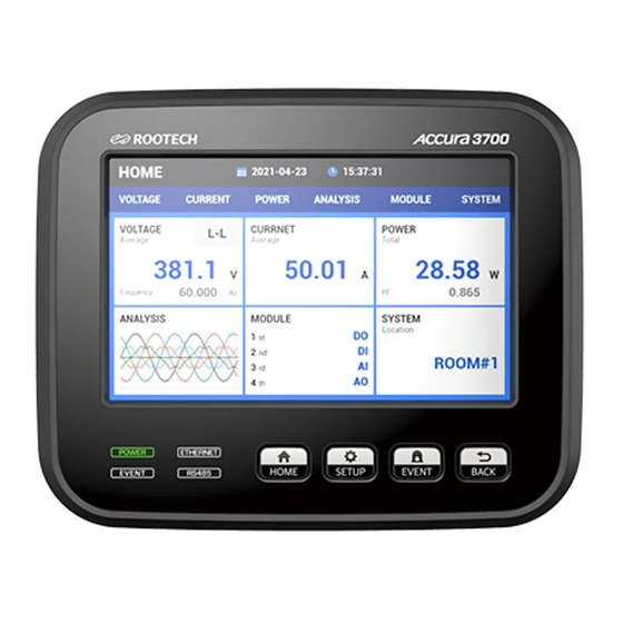
- Page 1 ACCURA 3700 High Accuracy Digital Power Quality Meter Installed at multiple locations within a facility Actually makes possible power quality measurement User Guide[English] Revision 1.12 2014/02/18...
- Page 2 Digital Power Quality Meter Accura 3700 Accura 3700 Rear Extension Module Accura 3700 DIO module Accura 3700 AI module Accura 3700 RTD module Accura 3700 DI module Accura 3700 AO module Accura 3700 ELD module Accura 3700 DO module Accura 3700 A4D2 module...
- Page 3 Indicates alternative voltage or current. Indicates direct voltage or current. Installation Considerations Installation and operation of Accura 3700 should be performed only by qualified, competent personnel that have appropriate training and experience with high voltage and current devices. Caution Failure to observe the following instructions may result in severe injury or death.
- Page 4 Accura 3700 User Guide Warning Observe the following instructions or permanent damage to the meter may occur. Do not apply Accura 3700 to voltages and currents that exceed onput ratings of PT and CT. Limitation of Liability Rootech Inc. reserves the right to make changes in the device specifications shown in this User Guide without notice.
- Page 5 Accura 3700 User Guide Notice Standard Compliance CE Approved MEASURING EQUIPMENT EN61326 and IEC61010 35DX E258934 KCC-REM-RTE-ACCURA 3700 KS Q ISO 9001:2009/ ISO 9001:2008 Certificate No: QMS-1347 ⓒ 2014 Rootech Inc. All Rights Reserved Page 5...
- Page 6 Rootech has been advised of the possibility of such damages. To the extent that a limitation or exclusion of consequential Damages are prohibited by applicable law, then Rootech’s liability shall be limited to twice the...
- Page 7 Accura 3700 User Guide Warranty Information Rootech shall not be liable for any claim- other than a claim solely for the breach of one of the above warranties that is made in accordance with the above described procedures- made by the...
- Page 8 Revision History Accura 3700 User Guide Revision History The following version of the Accura 3700 User Guide has been released. Revision Date Description Revision 1.0B 2013. 02. 22 Initial draft Revision 1.1 2014. 01. 07 First modification Revision 1.11 2014. 02. 05 AI modification Revision 1.12...
-
Page 9: Table Of Contents
RS485 Communication ......................42 Step 4: Accura 3700 Power Supply/Ground ................43 Power Wiring .......................... 43 Ground Terminal ........................43 Step 5: Accura 3700 Extension Module Addition ..............44 Step 6: I/O Module ........................ 45 DIO Module ........................... 45 DI Module ..........................48 DO Module.......................... - Page 10 DC] ....................153 Information [INFO Information] ..................163 Required Configuration Step ......................164 Accura 3700 Connection, PT Rating ..................164 APPENDIX A Specification ......................167 APPENDIX B Standard Compliance ....................169 APPENDIX C Accuracy/Reliability ....................170 Accuracy ..........................170 Reliability ..........................
- Page 11 Accura 3700 User Guide Contents INDEX............................175 ⓒ 2014 Rootech Inc. All Rights Reserved Page 11...
- Page 12 Fig 2.17 Accura 3700 Rear View ..................... 29 Fig 2.18 Accura 3700 Side View ..................... 29 Fig 2.19 Accura 3700 I/O Module Front View/Side View/Height ..........29 Fig 2.20 Accura 3700 Panel Installation[ANSI 4e ..............31 Fig 2.21 Accura 3700 Panel Installation[DIN96] ..............31 Fig 2.22 Voltage/Current Wiring .....................
- Page 13 Accura 3700 User Guide Contents Fig 2.35 Accura 3700 RS485 Communication ................. 42 Fig 2.36 Accura 3700 RS485 Communication Connection ............42 Fig 2.37 Accura 3700 Power Supply ..................43 Fig 2.38 I/O Module Addition ....................44 Fig 2.39 DIO Module ......................45 Fig 2.40 Digital Input (Dual Input Structure) ................
- Page 14 Accura 3700 User Guide Fig 3.4 Event Mode Screen Example ..................69 Fig 3.5 Accura 3700 Front Side Overview ................71 Fig 3.6 First Screen of Display Mode ..................74 Fig 3.7 Line to Neutral Voltage/Current/Power Display Screen ..........74 Fig 3.8 Specific Measured Value Line to Line Voltage Display Screen .........
-
Page 15: Chapter 1 Introduction
Quality information conforms to IEC61000-4-30 Class B. Aggregation Interval Maximum/Minimum/Average Information Accura 3700 provides the average value that corresponds to 0.2 second interval from the measurement value per cycle unit. Based on 0.2 second interval average value, Accura 3700 provides the average of 1 second, 5 second, 1 minute, 5 minute, 1 hour and 6 hour intervals. - Page 16 This includes the information of measuring parameter which often changes. So this makes it possible to accurate trend-analyzing about voltage, current and power. CE, UL, KCC, FCC safety and Reliability The internal/external structure [framework, circuit and fire] of Accura 3700 conforms to standard, CE[EN61326-1, EN61326-2-1], UL[UL61010-1 2 edition], KCC[KN22, KN24], FCC[Part15 Subpart B].
-
Page 17: Application
The most important thing deciding the data reliability of energy management is the degree of the accuracy of the digital meter. Accura 3700 measures highly accurate Reading 0.2% about the voltage and current, and power/amount of power conforms the compliance IEC62053-22 Class 0.2S. -
Page 18: Device Lineup
Accura 3700 and according to the composition of the I/O channel, various modules are provided. The number of the I/O modules adding to the Accura 3700 is 3. But, the number of repeated addition of AO modules is up to 2. Device... -
Page 19: Device Lineup
Chapter 1 Introduction Device Lineup Accura 3700 Power Quality Meter Accura 3700 performs 0.2% Reading accurately about voltage, and current Power/Energy conforms Accura 3700 provides IEC62053-22 Class 0.2S. Also due to distribution panel digital power metering various power quality information such as Dip[Sag], Swell, harmonics, Crest factor, K factor, and unbalance. - Page 20 Data can be achieved by not displayed on LCD but just by the communication. Accura 3700 provides statistic information (maximum, minimum, average) of voltage, current power through communication. This includes the information of metering parameter which often changes so this makes it possible to accurate trend-analyzing about voltage, current and power.
- Page 21 Available when the module is added. Temperature sensor which is installed on the rear of Accrua 3700 is not for fire watching, but for reference only. Accura 3700 has Ethernet switch function so network connection is available among Accura 3700s without the external switch.
- Page 22 Chapter 1 Introduction I/O Module Accura 3700 provides options; various modules can be easily added to the rear side of meter physically. Modules can be added up to 3 modules by non-order and same module addition is possible. But, the number of repeated addition of AO modules is up to 2.
- Page 23 Digital output supports the ON/OFF output, Single Pulse output, Periodic Pulse output and energy Pulse output. Analog output outputs converting the value of measurements or commanded communication for 0 ~ 20mA. Peak AC / DC Value, max 1A current is energizing cycle 100ms one-shot current. ⓒ 2014 Rootech Inc. All Rights Reserved Page 23...
-
Page 24: Chapter 2 Installation
Accura 3700 User Guide Chapter 2 Installation Environmental Conditions Accura 3700 should be mounted away from locations where there are direct interruption sources like high heat sand very high electric fields. For normal operation, environmental conditions should consider the following guidelines. -
Page 25: Before Installation
Accura 3700 User Guide Chapter 2 Installation Before Installation Before installing Accura 3700, observe the instructions and safety precautions presented in this guide. Caution Power up after voltage and current wiring is completed. Meter Overview Fig 2.1 Accura 3700 Front View Fig 2.2 Accura 3700 Side View... -
Page 26: Fig 2.4 Accura 3700 Dio Module
Chapter 2 Installation Accura 3700 User Guide Fig 2.4 Accura 3700 DIO Module Fig 2.5 Accura 3700 DI Module Fig 2.6 Accura 3700 DO Module Fig 2.7 Accura 3700 AI Module Fig 2.8 Accura 3700 AO Module Fig 2.9 Accura 3700 A4D2 Module Page 26 ⓒ... -
Page 27: Fig 2.10 Accura 3700 A2D4 Module
Accura 3700 User Guide Chapter 2 Installation Fig 2.10 Accura 3700 A2D4 Module Fig 2.11 Accura 3700 RTD Module Fig 2.12 Accura 3700 ELD Module Fig 2.13 Accura 3700 DC Module ⓒ 2014 Rootech Inc. All Rights Reserved Page 27... -
Page 28: Components
Accura 3700 User Guide Components Fig 2.14 Accura 3700 Components Accura 3700 Fixing nuts, bolts 2EA Rear protection cover Short bar Connector Fig 2.15 I/O Module Components Module protection I/O module cover Page 28 ⓒ 2014 Rootech Inc. All Rights Reserved... -
Page 29: Dimension
Chapter 2 Installation Dimension Fig 2.16 Accura 3700 Front View Fig 2.17 Accura 3700 Rear View Fig 2.18 Accura 3700 Side View Fig 2.19 Accura 3700 I/O Module Front View/Side View/Height ⓒ 2014 Rootech Inc. All Rights Reserved Page 29... - Page 30 Chapter 2 Installation Accura 3700 User Guide Model Dimension Device Model Dimension[mm] Power Quality Meter Accura 3700 127W x 114H x 78D I/O module DIO etc. 86.2W x 91H x 27D Page 30 ⓒ 2014 Rootech Inc. All Rights Reserved...
-
Page 31: Step 1: Panel Installation
Step 1: Panel Installation Accura 3700 Panel Installation Accura 3700 is installed at the front side of the distribution panel. ① Place the meter at the cutout of panel. [ANSI 4”, DIN96 Support] ② Mount the power connector to the right side of Accura 3700. -
Page 32: Step 2: Voltage/Current Wiring
Pollution degree 2, Installation Category Ⅲ PT[Potential Transformer] External PTs are required for all systems with voltage levels greater than these above. PTs should comply with IEC61010-1, Pollution Degree 2, Overvoltage Category Ⅲ. Page 32 ⓒ 2014 Rootech Inc. All Rights Reserved... - Page 33 > 3VA Note In case that peak expected load is remarkably lower than CT rated current, selecting the much lower rated current of CT can improve the accuracy and display resolution. ⓒ 2014 Rootech Inc. All Rights Reserved Page 33...
-
Page 34: Fig 2.23 3 Phase 4 Wire 3Pt, 3Ct Wiring, Wiring Mode[Conn] = 3P4U
- In case of wiring without CT, wiring must be done followed by guidelines of the company. Fig 2.23 3 Phase 4 Wire 3PT, 3CT Wiring, Wiring Mode[CONN] = 3P4U Note Select 3P4U in “Connection” menu screen. Page 34 ⓒ 2014 Rootech Inc. All Rights Reserved... -
Page 35: Fig 2.24 3 Phase 3 Wire 2Pt 3Ct Wiring, Wiring Mode[Conn] = 3P3U
Fig 2.24 3 Phase 3 Wire 2PT 3CT Wiring, Wiring Mode[CONN] = 3P3U Note Select 3P3U in “Connection” menu screen. Fig 2.25 3 Phase 3 Wire 2PT, 2CT wiring, Wiring Mode[CONN] = 3P3U Note Select 3P3U in “Connection” menu screen. ⓒ 2014 Rootech Inc. All Rights Reserved Page 35... -
Page 36: Fig 2.26 1 Phase 3 Wire 2Pt 2Ct Wiring, Wiring Mode[Conn] = 1P3U
Note Select 1P3U in “Connection” menu screen. Fig 2.27 1 Phase 2 Wire 1PT 1CT Wiring, Wiring Mode[CONN] = 1P2U Note terminal must be used. Select 1P2U in “Connection” menu screen. Page 36 ⓒ 2014 Rootech Inc. All Rights Reserved... -
Page 37: Fig 2.28 3 Phase 4 Wire Direct 3Ct Wiring, Wiring Mode[Conn] =3P4U
Fig 2.28 3 Phase 4 Wire Direct 3CT Wiring, Wiring Mode[CONN] =3P4U Note Select 3P4U in “Connection” menu screen. Fig 2.29 3 Phase 3 Wire Voltage Direct 3CT Wiring, Wiring Mode[CONN]=3P3U Note Select 3P3U in “Connection” menu screen. ⓒ 2014 Rootech Inc. All Rights Reserved Page 37... -
Page 38: Fig 2.30 3 Phase 3 Wire Voltage Direct 2Ct Wiring, Wiring Mode[Conn]=3P3U
Fig 2.30 3 Phase 3 Wire Voltage Direct 2CT Wiring, Wiring Mode[CONN]=3P3U Note Select 3P3U in “Connection” menu screen. Fig 2.31 1 Phase 3 Wire Voltage Direct 2CT Wiring, Wiring Mode[CONN]=1P3U Note Select 1P3U in “Connection” menu screen. Page 38 ⓒ 2014 Rootech Inc. All Rights Reserved... -
Page 39: Fig 2.32 1 Phase 3 Wire Voltage Direct 1Ct Wiring, Wiring Mode[Conn]=1P2U
Accura 3700 User Guide Chapter 2 Installation Fig 2.32 1 Phase 3 Wire Voltage Direct 1CT Wiring, Wiring Mode[CONN]=1P2U Note and V terminals must be used. Select 1P2U in “Connection” menu screen. ⓒ 2014 Rootech Inc. All Rights Reserved Page 39... -
Page 40: Step 3: Accura 3700 External Communication
Accura 3700 supports the Ethernet communication for upper collecting programs and high speed transmission of measured data. Inside of Accura 3700, Ethernet switch built in so using 2 Ethernet ports Ethernet connection is available among 3700s without another external switch. Up to 20 Accura 3700s can be connected and Star, Daisy Chain and Ring wiring modes are available. -
Page 41: Fig 2.34 Accura 3700 Ehternet Connection
Accura 3700 User Guide Chapter 2 Installation Fig 2.34 Accura 3700 Ehternet Connection Recommend using the Ethernet switch supporting the RSTP[Rapid Spanning Tree] protocol for quick recovery when ring wiring. Ethernet cable maximum 100m Connection of up to 20 Accura 3700s available. -
Page 42: Rs485 Communication
Chapter 2 Installation Accura 3700 User Guide RS485 Communication Accura 3700 supports RS485 Communication 1 port together with Ethernet Communication. Fig 2.35 Accura 3700 RS485 Communication Fig 2.36 Accura 3700 RS485 Communication Connection RS485 Port 1 Item Description Port Name... -
Page 43: Step 4: Accura 3700 Power Supply/Ground
Accura 3700 User Guide Chapter 2 Installation Step 4: Accura 3700 Power Supply/Ground Fig 2.37 Accura 3700 Power Supply Power Wiring Item Description Connector Name L+, N- Connector Type Screw Terminal[Pluggable] Wiring 2.1 to 3.5 mm [14 to 12 AWG]... -
Page 44: Step 5: Accura 3700 Extension Module Addition
Chapter 2 Installation Accura 3700 User Guide Step 5: Accura 3700 Extension Module Addition To install extension module at the rear of Accura 3700, remove the rubber cover which is for rear connector protection. Fig 2.38 I/O Module Addition Note Accura 3700 can connect 3 modules maximum regardless of the type of module. -
Page 45: Step 6: I/O Module
Connector Type Screw type terminal [Pluggable] Application Dry contact Wiring Compliance 0.21 to 3.5 mm [24 to 12 AWG] Rating DC 5V[Self excitation] Insulation AC 2,000V 1 minute Minimum Pulse Width 10msec ⓒ 2014 Rootech Inc. All Rights Reserved Page 45... -
Page 46: Fig 2.40 Digital Input (Dual Input Structure)
Operation of the digital output type is followed Peak AC / DC Value, max 1A current is energizing cycle 100ms one-shot current. Output Type Command Latch “on” outputs “off” outputs Periodic pulse Periodic pulse outputs Periodic pulse stops Page 46 ⓒ 2014 Rootech Inc. All Rights Reserved... -
Page 47: Fig 2.41 Dc Relay Application
Fig 2.41 DC Relay Application Fig 2.42 AC Relay Application Note Recommend to use Clamp Diode or Varistor not to power up to exceeding the rating voltage to digital output during switching. ⓒ 2014 Rootech Inc. All Rights Reserved Page 47... -
Page 48: Di Module
Screw Type TerminalPluggable] Application Dry contact Wiring Compliance 0.21 to 3.5 mm [24 to 12 AWG] Rating DC 5V[Self excitation] Insulation Maximum AC 2,000V for 1 minute Minimum Pulse Width 10msec Page 48 ⓒ 2014 Rootech Inc. All Rights Reserved... -
Page 49: Fig 2.44 Digital Input (Dual Input Structure)
Accura 3700 User Guide Chapter 2 Installation Fig 2.44 Digital Input (Dual Input Structure) Warning Applying external power can damage the meter due to internal 5V output on Dry Contact terminal. ⓒ 2014 Rootech Inc. All Rights Reserved Page 49... -
Page 50: Do Module
Output Type Command Latch “on” outputs “off” outputs Periodic pulse Periodic pulse outputs Periodic pulse stops Single Single pulse outputs. Additional generations of “on” command pulse[uncountable] within pulse period are ignored. Page 50 ⓒ 2014 Rootech Inc. All Rights Reserved... -
Page 51: Fig 2.46 Dc Relay Application
Fig 2.46 DC Relay application Fig 2.47 AC Relay application Note Recommend to use Clamp Diode or Varistor not to power up to exceeding the voltage rating to digital output during switching. ⓒ 2014 Rootech Inc. All Rights Reserved Page 51... -
Page 52: Ai Module
0.21 to 3.5 mm [24 to 12 AWG] Compliance Current Input DC 0 ~ 20mA Accuracy ±0.5% Full Scale Fig 2.49 Analog Input Warning Applying current exceeding 20mA can damage the internal circuit. Page 52 ⓒ 2014 Rootech Inc. All Rights Reserved... -
Page 53: Ao Module
Impedance Below 450Ω Accuracy ±0.5% Full Scale Fig 2.51 AO Module Analog Output Warning At voltage drop exceeding 10V on 0 ~ 20mA current output, constant current output is not guaranteed. ⓒ 2014 Rootech Inc. All Rights Reserved Page 53... -
Page 54: A4D2/A2D4 Module
Item Description Connector Type Screw Type Terminal[Pluggable] Wiring 0.21 to 3.5 mm [24 to 12 AWG] Compliance Current Output DC 0 ~ 20mA Load Restriction Below 450Ω Accuracy ±0.5% Full Scale Page 54 ⓒ 2014 Rootech Inc. All Rights Reserved... -
Page 55: Fig 2.54 A4D2/A2D4 Module Analog Output
Latch, Pulse, Periodic Pulse , Energy Pulse Minimum Pulse Period 20msec Minimum Pulse Width 10msec Insulation AC 2,000V 1 minute Maximum Rating AC/DC 400V 350mA[max. 1A] Operation of the digital output type is followed. ⓒ 2014 Rootech Inc. All Rights Reserved Page 55... -
Page 56: Fig 2.55 Dc Relay Application
Peak AC / DC Value, max 1A current is energizing cycle 100ms one-shot current Note For selection of Latch or pulse type, refer the “Output Channel type” setup menu of DO module setting. Fig 2.55 DC Relay application Page 56 ⓒ 2014 Rootech Inc. All Rights Reserved... -
Page 57: Fig 2.56 Ac Relay Application
Accura 3700 User Guide Chapter 2 Installation Fig 2.56 AC Relay application Note Recommend to use Clamp Diode or Varistor not to power up to exceeding the voltage rating to digital output during switching. ⓒ 2014 Rootech Inc. All Rights Reserved Page 57... -
Page 58: Rtd Module
Item Description Connector Type Screw Type Terminal[Pluggable] Wiring 0.21 to 3.5 mm [24 to 12 AWG] Compliance RTD Sensor PT100, PT1000 Wiring Mode 2, 3, 4 wires Accuracy ±0.5% Full Scale Page 58 ⓒ 2014 Rootech Inc. All Rights Reserved... -
Page 59: Fig 2.58 Rtd Input
Accura 3700 User Guide Chapter 2 Installation Fig 2.58 RTD Input [4Wires] [3Wires] [2Wires] ⓒ 2014 Rootech Inc. All Rights Reserved Page 59... -
Page 60: Eld Module
Connector Type Screw Type Terminal[Pluggable] Wiring Compliance 0.21 to 3.5 mm [24 to 12 AWG] Leakage Current Input Voltage-type ZCT 200mA/100mV @ 1.2kΩ Burden Accuracy ±0.5% Full Scale Fig 2.60 ELD Input Page 60 ⓒ 2014 Rootech Inc. All Rights Reserved... - Page 61 Peak AC / DC Value, max 1A current is energizing cycle 100ms one-shot current. Note For selection of Latch or pulse type, refer to the “Output Channel type” setup menu of DO module setting. ⓒ 2014 Rootech Inc. All Rights Reserved Page 61...
-
Page 62: Fig 2.61 Dc Relay Application
Fig 2.61 DC Relay Application Fig 2.62 AC Relay Application Note Recommend to use Clamp Diode or Varistor not to power up to exceeding the voltage rating to digital output during switching. Page 62 ⓒ 2014 Rootech Inc. All Rights Reserved... -
Page 63: Dc Module
Screw Type Terminal[Pluggable] Shunt [Rectifier Output Current] 50, 60, 100mV Shunt [Battery Current] ±50, 50, 60, 100mV Wiring Compliance 0.21 to 3.5 mm [24 to 12 AWG] Fig 2.64 DC Voltage/Current ⓒ 2014 Rootech Inc. All Rights Reserved Page 63... -
Page 64: Fig 2.65 Digital Input(Dual Input Structure)
AC 2,000V 1 minute Minimum Pulse Width 10msec Fig 2.65 Digital Input(Dual Input Structure) Warning Applying external power can damage the meter due to internal 5V output on Dry Contact terminal. Page 64 ⓒ 2014 Rootech Inc. All Rights Reserved... - Page 65 Peak AC / DC Value, max 1A current is energizing cycle 100ms one-shot current Note For selection of Latch or pulse type, refer to the “Output Channel type” setup menu of DO module setting. ⓒ 2014 Rootech Inc. All Rights Reserved Page 65...
-
Page 66: Fig 2.66 Dc Relay Application
Fig 2.66 DC Relay application Fig 2.67 AC Relay application Note Recommend to use Clamp Diode or Varistor not to power up to exceeding the voltage rating to digital output during switching. Page 66 ⓒ 2014 Rootech Inc. All Rights Reserved... -
Page 67: Chapter 3 Operation/Setup
Accura 3700 User Guide Chapter 3 Operation/Setup Front side of Accura 3700 consists of LCD, which shows measurement information and setup, 4 LEDs which indicate power supply and communication status and 4 buttons which enables selection of all the operation states. -
Page 68: Fig 3.2 Display Mode Screen Example
Also in the state that the event does not generate, you can confirm the event logs by long-touching EVENT button. In the Event mode, Event segment above bar is lighted up. Page 68 ⓒ 2014 Rootech Inc. All Rights Reserved... -
Page 69: Fig 3.4 Event Mode Screen Example
In the setup mode, navigation menu below LCD changes from the [DISPLAY] Mode to [SETUP] mode. When event occurs, RED backlight is kept for basically 10 seconds and additional setup is available up to 999 minutes. ⓒ 2014 Rootech Inc. All Rights Reserved Page 69... - Page 70 Automatically return to display mode if there is no button operation for 10 minutes at the setup mode. Automatically return to setup mode if there is no button operation for 1 minute changing the setup value. Page 70 ⓒ 2014 Rootech Inc. All Rights Reserved...
-
Page 71: Display Mode
Accura 3700 User Guide Chapter 3 Operation/Setup Display Mode Front View Fig 3.5 Accura 3700 Front Side Overview Voltage Current Active Power Reactive Power Apparent Power Energy Power Factor Line to Neutral Line to Line Total Harmonic Distortion Fundamental FUND... - Page 72 Module element MODULE Meter information element INFO Reserved Start-up Preparation Time Accura 3700 requires start-up preparation time for about 10~30 seconds after power up. In the meantime, LCD screen is not displayed. Page 72 ⓒ 2014 Rootech Inc. All Rights Reserved...
-
Page 73: Display Screen
Accura 3700 User Guide Chapter 3 Operation/Setup Display Screen Accura 3700 displays information of measurement parameter and status of extension module selected. ⓒ 2014 Rootech Inc. All Rights Reserved Page 73... -
Page 74: Measurement Parameter Display Screen
By touching Down[v] key, you can see the line to neutral voltage, maximum and minimum, line to line of each lines, voltage THD, and frequency displayed. By touching Up[v]key, values are displayed in opposite order. Page 74 ⓒ 2014 Rootech Inc. All Rights Reserved... -
Page 75: Fig 3.8 Specific Measured Value Line To Line Voltage Display Screen
Down[v] key, ineffective power, superficial power, maximum and minimum of effective power, maximum of ineffective power and superficial power, and power factor are displayed in order. By touching Up[v]key, values are displayed in opposite order. ⓒ 2014 Rootech Inc. All Rights Reserved Page 75... -
Page 76: Fig 3.10 Power Specific Measure Value Display Screen
By touching Up[v]key, values are displayed in opposite order. Net energy is the value which subtracts deliver energy from receive energy, and total energy is the value which sums receive energy and deliver energy. Page 76 ⓒ 2014 Rootech Inc. All Rights Reserved... -
Page 77: Fig 3.12 Net Energy Display Screen
Designated port Way to RSTP Leaf Node Backup port Alternative Way to Same LAN Alternative port Alternative Way to RSTP Root Node Connecting Port Connected Deciding RSTP Role No connection Port Disconnected ⓒ 2014 Rootech Inc. All Rights Reserved Page 77... -
Page 78: Fig 3.14 Temperature Display Screen Of Etc
At the INFO display screen, if you touch the Right[>] key again, this makes shift to the ETC screen [ETC]. At ETC screen, you can confirm the measured temperature by the temperature sensor which is added at the rear case of Accura 3700 and present time. Fig 3.14 Temperature Display Screen of ETC Page 78 ⓒ... -
Page 79: Extension Module State View
Extension Module State View State of extension module of Accura 3700 is divided into the page that confirms the number of module and the ID of each module and the page that can watch the state of each channel for each module. -
Page 80: Module
Fig 3.17 Among Module Pages , Screen that Displays Channel Information of Second Extension Module Up to 3 extension modules can be installed at the rear side of Accura 3700. Even though other modules are supported adding the same sort of models, but AO modules can added only 2 maximum. -
Page 81: Display Screen For Classification Of Extension Modules
Accura 3700 User Guide Chapter 3 Operation/Setup Display Screen for Classification of Extension Modules Accurara 3700 indicates the state information of classification of extension modules ⓒ 2014 Rootech Inc. All Rights Reserved Page 81... -
Page 82: Fig 3.18 Dio Module First Screen
‘ㅁ’. The following chart indicates the state of contact point as to DO display state corresponding to the setup value of Polarity input. Polarity Normal setup is responding to the contact point A and Polarity Reverse setup is to the contact point B. Page 82 ⓒ 2014 Rootech Inc. All Rights Reserved... -
Page 83: Fig 3.19 Di Module First Screen
6 channels is displayed through 2 screens. Each screen can be confirmed in order by using Up[^], Down[v] keys. Fig 3.20 DO Module First Screen ⓒ 2014 Rootech Inc. All Rights Reserved Page 83... -
Page 84: Fig 3.21 Ai Module First Screen
For example, if the value of average current which is measure by Accura 3700 that ranges 0~100A is converged into 4~20mA outputs as AO channel and 50A current is measured 12mA is displayed at the third row of AO channel screen and 50 is displayed at fourth row. -
Page 85: Fig 3.22 Ao Module First Screen
Each screen can be confirmed in order by using Up[^], Down[v] keys. Analog output channel has same features with AO module channel and digital output channel has with DO module channel. ⓒ 2014 Rootech Inc. All Rights Reserved Page 85... -
Page 86: Fig 3.24 A2D4 Module First Screen
Screen for each channel can be confirmed in order by using Up[^], and Down[v] key. Digital output channel has same function with DO module channel. Fig 3.26 ELD Module Primary Screen Page 86 ⓒ 2014 Rootech Inc. All Rights Reserved... -
Page 87: Fig 3.27 Dc Module First Screen
Up[^], and Down[v] key. Digital input channel has same function with DI module channel, and digital output channel has same function with DO module channel. Fig 3.27 DC Module First Screen ⓒ 2014 Rootech Inc. All Rights Reserved Page 87... -
Page 88: Event Mode
Event Mode Event Alarm In the case that events such as Dip[Sag], Swell, Fuse Fail are set up, Accura 3700 displays the event alarm on the upper side of LCD screen if the condition of events met. In the generation of event such as Dip[Sag], Swell, LCD backlight turn into red color. - Page 89 “[Beep]” sounds when touching. Touch more than one second. After one second, “[Beep]” sounds. Note Accura 3700 automatically returns to the display mode if there is no button pressing for 10 minutes in event mode. ⓒ 2014 Rootech Inc. All Rights Reserved...
-
Page 90: Fig 3.30 Event Log Number Example
E998 E999 Final Event Log number E999 Final Event Log number Event Log number is followed. Event Log number N-499 Oldest saved event Event Log number N Most recently saved event Page 90 ⓒ 2014 Rootech Inc. All Rights Reserved... - Page 91 000 ~ 999 SUL.S[Swell Swell Start Event generates[B phase Start] Voltage when Swell Start Event [d][d][d][d] v generates Event Phase [A, B, C, AB, BC, CA] is displayed. d decimal[10] ⓒ 2014 Rootech Inc. All Rights Reserved Page 91...
- Page 92 Display the information when Fuse Fail End event generates Display Event number - E[Event] [d][d][d] 000 ~ 999 Fuse Fail end event generates[B - B FuSE[Fuse] phase] End[End] Event Phase [A, B, C] is displayed. d decimal[10] Page 92 ⓒ 2014 Rootech Inc. All Rights Reserved...
- Page 93 Event number E[Event] [d][d][d] 000 ~ 999 DI Close event generates dI.cL[DI Close], DIO, DI. DC etc. module name dI[DI] 1 ~ 12 [indicate the event Ch.[d][d] generated channel] d decimal[10] ⓒ 2014 Rootech Inc. All Rights Reserved Page 93...
- Page 94 E[Event] [d][d][d] 000 ~ 999 AI Over event generates aI.ou[AI Over], AI, DC, RTD, ELD etc. module name AI[AI] 1 ~ 6 [indicate the event generated channel] Ch.[d] d decimal[10] Page 94 ⓒ 2014 Rootech Inc. All Rights Reserved...
- Page 95 RTD module name 1 ~ 3[indicate the event generated Ch.[d] channel] d decimal[10] No Event Logs The information of no event logs generated is displayed Display No event logs No[no] Evnt[Event] ⓒ 2014 Rootech Inc. All Rights Reserved Page 95...
-
Page 96: Setup Mode
Left[<], Up[^], Down[v], Right[>], ESC, and ENTER button. At this time in the space of navigation menu of lower side of LCD, setup menu is displayed, so you can confirm easily where the page displayed now. Page 96 ⓒ 2014 Rootech Inc. All Rights Reserved... -
Page 97: Setup Menu
Accura 3700 User Guide Chapter 3 Operation/Setup Setup Menu ⓒ 2014 Rootech Inc. All Rights Reserved Page 97... -
Page 98: Meter Setup
PT primary and secondary conversion ratio. Ct CT CT Rating [ Setting Range CT Primary Rating - Pr[Primary] [d][d][d][d][d].[d] 00000.1 ~ 99999.9 CT Secondary Rating - Sc[Secondary] [d][d].[d] 00.1 ~ 99.9 d decimal[10] Page 98 ⓒ 2014 Rootech Inc. All Rights Reserved... - Page 99 Reference current is used as the reference value of TDD setting. Also it is used as the reference of front bar display. Demand Sub Interval [dMd Demand, SbIt Sub Interval] Setting Range 1 ~ 60 minute[default 15] ⓒ 2014 Rootech Inc. All Rights Reserved Page 99...
-
Page 100: Fig 3.31 Demand Measuring Method
Demand Measurement Method Accura 3700 uses the [Sliding Window] Demand Measuring Method. Demand time [minute]= demand sub interval x Number of demand sub intervals. Ex] for the case with 15 minute demand time, demand sub interval is 15minutes and number of demand sub intervals is 1. -
Page 101: Fig 3.32 Power Sign[General Calculation]
Lead[P<0, Q>0] Lag[P>0, Q>0] Note In the case of leading or lagging of current phase, PF is displayed as in the front view of Accura 3700. Method 2: method that calculates the reactive power from measured active and apparent ... - Page 102 This meter supports two methods that calculate the sum power form each phase power. [3 phase line- 3 phase sum power] Method 1: [Vector Sum] PF = Method 2: [Arithmetic Sum] − PF = Page 102 ⓒ 2014 Rootech Inc. All Rights Reserved...
-
Page 103: Fig 3.33 Difference Between Two Methods That Calculate Each Phase Sum Power
0 to the current value under the set value. Unit is mA and external CT secondary input at Accura 3700 is the reference. In case of setting 20ma, default value, the secondary rating which is 5A would be displayed 0 as 1/250 below of the rating. - Page 104 1 and 0. Uar Var, SIgnSign Reactive Power Sign Display ON/OFF [ Setting Range Display sign as to the current phase on[ON, default] Do not display the sign to reactive power oFF[OFF] Page 104 ⓒ 2014 Rootech Inc. All Rights Reserved...
- Page 105 ON at this setting, the sign is given to reactive power. To always process the reactive power regardless to the calculation method of reactive power, OFF the Var Sign at this setting. ⓒ 2014 Rootech Inc. All Rights Reserved Page 105...
-
Page 106: Event Setup
Dip Event [ Setting Range Dip event on on[ON] Dip event off oFF[OFF, default] SuL Swell, Eunt Event Swell Event [ Setting Range Swell event on on[ON] Swell event off oFF[OFF, default] Page 106 ⓒ 2014 Rootech Inc. All Rights Reserved... - Page 107 In case of 3P3U Setting Range Ratio to voltage reference 1.0 ~ 98.0% [default 90.0%] Dip Start Voltage Display [3P3U] Voltage line to line [voltage reference] [d][d][d].[d] V/kV x percentage ⓒ 2014 Rootech Inc. All Rights Reserved Page 107...
- Page 108 In case of 3P3U Setting Range Ratio to voltage reference 1.0 ~ 98.0% [default 90.0%] Dip End Voltage Display [3P3U] Voltage line to line [voltage reference] [d][d][d].[d] V/kV x percentage Page 108 ⓒ 2014 Rootech Inc. All Rights Reserved...
-
Page 109: Fig 3.34 Dip Event Configuration[Three Phase 3 Wires]
Example of the case that setting the voltage reference of METER setup page as 380V. Fig 3.35 Dip Event Configuration[Three Phase 4 Wires] Example of the case that setting the voltage reference of METER setup page as 380V. ⓒ 2014 Rootech Inc. All Rights Reserved Page 109... - Page 110 In case of 3P3U Setting Range Ratio to voltage reference 102.0 ~ 999.0% [default 110.0%] Swell Start Voltage Display Voltage line to line [voltage [d][d][d].[d] V/kV reference] x percentage Page 110 ⓒ 2014 Rootech Inc. All Rights Reserved...
- Page 111 In case of 3P3U Setting Range Ratio to voltage reference 101.0 ~ 998.0% [default 108.0%] Swell End Voltage Display Voltage line to line [voltage reference] [d][d][d].[d] V/k x percentage ⓒ 2014 Rootech Inc. All Rights Reserved Page 111...
-
Page 112: Fig 3.36 Swell Event Setup[3P3U]
Fuse Fail event ON Fuse Fail event OFF oFF[default] Case that voltage is measured as 0 for each phase and current is measured as not 0 is decided as Fuse Fail. Page 112 ⓒ 2014 Rootech Inc. All Rights Reserved... - Page 113 Black Out Event[bLAk Out Black Out ] Setting Range Black Out event ON Black Out event OFF oFF[default] Case that both voltage and current are measured as 0 is decided as Black out. ⓒ 2014 Rootech Inc. All Rights Reserved Page 113...
-
Page 114: Rs485 Communication Setup
57600 bps 57600 115200 bps 11520 Prty Parity Bit Parity Bit [ Setting Range Even Parity EuEn[default] None Parity nonE Odd Parity Stop Bit [ StoP Stop Bit Setting Range 1[default] Page 114 ⓒ 2014 Rootech Inc. All Rights Reserved... - Page 115 RS485 Communication Map Setup[ Setting Range A3700 Map a3700 [default] RTM200 Map r200 Setting the communication map is for r200, communication is available with Rootech’s product RTM200 in the same Map. ⓒ 2014 Rootech Inc. All Rights Reserved Page 115...
-
Page 116: Ethernet Network Setup
ETHERNET NETWORK SETUP IPIP Setting Range 000.000.000.000 ~ 255.255.255.255 [default 010.010.010.100] Sbnt Subnet Mask Subnet Mask[ Setting Range 255.255.000.000 ~ 255.255.255.252 [default 255.255.255.000] gatE Gateway Gateway[ Setting Range 000.000.000.000 ~ 255.255.255.255 [default 010.010.010.001] Page 116 ⓒ 2014 Rootech Inc. All Rights Reserved... - Page 117 ENTER key again, so blinks stops and Time Sync is completed. ntPS NTP Server NTP Server [ For setting the time sync of Accura 3700, input the server IP of NTP[Network Time Protocol]. Setting Range 000.000.000.000 255.255.255.255 [default 010.010.010.001] ⓒ...
-
Page 118: Reset
Demand Demand Reset [ ] Reset [ Setting Range Demand Reset rESEt[Reset] Maximum/Minimum Reset[Max Maximum, MinMinimum] Reset Setting Range Maximum/minimum reset rESEt[Reset] Demand Maximum is reset by the maximum/minimum reset. Page 118 ⓒ 2014 Rootech Inc. All Rights Reserved... - Page 119 Accura 3700 User Guide Chapter 3 Operation/Setup Enrg Energy Energy Reset [ Setting Range Energy[kWh, kVARh, kVAh] reset rESEt[Reset] ALL ALL All Reset [ Setting Range All [Demand, Maximum/Minimum. rESEt[Reset] Energy] reset ⓒ 2014 Rootech Inc. All Rights Reserved Page 119...
-
Page 120: Display Setup
Brightness changes to ‘LCD Brightness’ below Low set value after touching the last key and this setting time pass to lower the power consumption. Eunt Event, b.Lgt Back Light LCD Event RED Back Light Time [ Setting Range 0 ~ 999 min[default 0] Page 120 ⓒ 2014 Rootech Inc. All Rights Reserved... - Page 121 Demo mode setup. Current is provided regardless of Demo sort. The size of current is the value multiplying 0.2A with CT ratio [provide 2A when default CT rating ratio is 10, the phase keeps the lag feature about the voltage. ⓒ 2014 Rootech Inc. All Rights Reserved Page 121...
- Page 122 Swell Swell Cycle: 5cycles event Swell Size: 130% of voltage reference Voltage Change after Demo starts: Vref 15cycle kept → Dip 5 cycles generates → Kept after returning to Vref Page 122 ⓒ 2014 Rootech Inc. All Rights Reserved...
-
Page 123: Extension Module Id Setup [Module]
‘State Change Notice’ is provided through communication and ⓒ 2014 Rootech Inc. All Rights Reserved Page 123... - Page 124 If the composition and setting changes of modules are detected, blinking as “Save” and long touching the ENTER key activating the setup saving changes into “Saved” and notifies that it is saved latest date state. Module Setup Information Save Change detected Save Saved Setting saved Page 124 ⓒ 2014 Rootech Inc. All Rights Reserved...
-
Page 125: Separate Extension Module Setup
The following chart is arranging the sort of modules and channels per modules of Accura 3700. As seen at the chart, there are modules with one sort of channel and more than two sorts of channels. -
Page 126: Module Setup Screen
Chapter 3 Operation/Setup Accura 3700 User Guide Module Setup Screen Page 126 ⓒ 2014 Rootech Inc. All Rights Reserved... -
Page 127: Di Module Setup [Di Di ]
Recognized as setting is changed 10 ~ 255msec [default 10msec] that input state is kept over the setup time. It is setting item not for reacting at chattering and noise signal. d decimal[10] ⓒ 2014 Rootech Inc. All Rights Reserved Page 127... - Page 128 DI Module Software Version [SUEr Software version, b bootload version, F Firmware Version] Screen to confirm the installed boot load and firmware version of installed DC modules. Display Boot load version Firmware version [d].[d][d] d decimal[10] Page 128 ⓒ 2014 Rootech Inc. All Rights Reserved...
-
Page 129: Do Module Setup[Do Do ]
Single Pulse(uncounted) PuLS.U[Pulse Uncounted] Single Pulse(counted) PuLS.C[Pulse Counted] Operation of the digital output type is followed. Output Type Command Latch “on” outputs “off” outputs Periodic pulse Periodic pulse outputs Periodic pulse stops ⓒ 2014 Rootech Inc. All Rights Reserved Page 129... - Page 130 Setting Range 0.01 ~ 10.00 sec. [d][d].[d][d] default Should be lower than pulse period value. 0.10] Operates as Latch mode if it is same with the pulse period. d decimal[10]. Page 130 ⓒ 2014 Rootech Inc. All Rights Reserved...
- Page 131 Output corresponding DO channel ㅏ [Leakage Current] in case of leakage current through ELD module Output corresponding DO channel ㅏ .Out[Black Out] in case of Black out event ⓒ 2014 Rootech Inc. All Rights Reserved Page 131...
- Page 132 “Pulse connected output”. Set the energy that corresponds for single pulse output. Setting Range 0.01 ~ 99.99 [d][d].[d][d] [default 0.35] Unit: kWh, kVarh d decimal[10]. Page 132 ⓒ 2014 Rootech Inc. All Rights Reserved...
- Page 133 DO Direct Control [do_1 DO Channel 1, CtrL Control ] Setting that ON/OFF controlling the DO channel at the front of Accura 3700. At “Output channel type” setup menu in case of selecting the countable single pulse type [PuLS.C] and operating as “Pulse connected output”, DO direct control is not supported.
-
Page 134: Dio Module Setup [Dio Dio]
DIO module has 8 DI channels. Setting Range Display ON when the external ∩ [Normal, default] contact point is ON. Display OFF when the external rEu[Reverse] contact point is OFF . d decimal[10] Page 134 ⓒ 2014 Rootech Inc. All Rights Reserved... -
Page 135: Ai Module Setup [Ai Ai]
In case of setting type of input range 4 ~ 20mA, setting input value (high value, u1) about input current 20mA, and value 2 (low value, u2) about 4mA, then provides the input current converged by the following equation. Input u1 and u2 can be both u1>u2 and u1. ⓒ 2014 Rootech Inc. All Rights Reserved Page 135... - Page 136 -99999.9 ~ 99999.9 [s][d][d][d][d][d].[d] 1, 2 [default: 0] Minimum input current [real value corresponding at 0mA or 4mA] d decimal[10]. S Sign select ‘0’[positive] ‘-‘[negative] by using Up[^], Down[v] Page 136 ⓒ 2014 Rootech Inc. All Rights Reserved...
- Page 137 On the other hand, ON, the Sign setting if reverse polarity signal is input it is measured proportionally as a small value. ⓒ 2014 Rootech Inc. All Rights Reserved Page 137...
- Page 138 In case that input value goes up and down around the event alarm reference Hysteresis value, there can be so many events. So adequate hysteresis setup is necessary for effective event managing. Page 138 ⓒ 2014 Rootech Inc. All Rights Reserved...
- Page 139 AI Module Software Version[SUEr Software version, b bootload version, FFirmware Version ] Screen to confirm the installed boot load and firmware version of installed AI modules. Display Boot load version Firmware Version [d].[d][d] d decimal[10] ⓒ 2014 Rootech Inc. All Rights Reserved Page 139...
-
Page 140: Ao Module Setup [Ao Ao]
decimal[10] Analog signal is output at AO channel connecting with the set measuring parameter. In case it is set as ‘NO’ required size of signal can be output through the communication. Page 140 ⓒ 2014 Rootech Inc. All Rights Reserved... - Page 141 Output value over u1 is limitedly output 20mA and under u2 output 4mA. Output can be both u1>u2 and u1<u2 (u1≠u2). 20 − 4 Output Current [ mA ] = ∗ ( Output value − u2 ) + 4 ��1 − ��2 ⓒ 2014 Rootech Inc. All Rights Reserved Page 141...
- Page 142 AO Module Software Version[SUEr Software version, b bootload version, F Firmware Version] Screen to confirm the installed boot load and firmware version of installed AO modules. Display Boot load version Firmware version [d].[d][d] d decimal[10] Page 142 ⓒ 2014 Rootech Inc. All Rights Reserved...
-
Page 143: A4D2 Module Setup [Module][A4D2 A4D2]
A4D2 Module Software Version [SUEr Software version, b bootload version, F Firmware Version ] Screen to confirm the installed boot load and firmware version of installed A4D2 modules. Display Boot load version Firmware version [d].[d][d] d decimal[10] ⓒ 2014 Rootech Inc. All Rights Reserved Page 143... -
Page 144: A2D4 Module Setup [A2D4 A2D4]
A2D4 Module Software Version [SUEr Software version, b bootload version, F Firmware Version] Screen to confirm the installed boot load and firmware version of installed A2D4 modules. Display Boot load version Firmware version [d].[d][d] d decimal[10] Page 144 ⓒ 2014 Rootech Inc. All Rights Reserved... -
Page 145: Rtd Module Setup [Rtd Rtd]
ON and Off of events of RTD not connected or disconnected RTD Wire Method[Ch_1 RTD Channel 1, Conn Connection ] Setting Range 2-Wire sensor 3-Wire sensor 3-W[default] 4-Wire sensor ⓒ 2014 Rootech Inc. All Rights Reserved Page 145... - Page 146 In case that input value goes up and down around the event alarm reference Hysteresis value, there can be so many events. So adequate hysteresis setup is necessary for effective event managing. Page 146 ⓒ 2014 Rootech Inc. All Rights Reserved...
- Page 147 RTD Channel Alarm Hysteresis Value Setup [Ch_I RTD Channel 1, hySt Hysteresis Value] Only generated when the event setting of RTD Channel is not ‘oFF’, set the hysteresis value. Setting Range 5 ~ 999d] [d][d][d] [default 5nge d decimal[10] ⓒ 2014 Rootech Inc. All Rights Reserved Page 147...
- Page 148 RTD Module Software Version [SUEr Software version, b bootload version, F Firmware Version] Screen to confirm the installed boot load and firmware version of installed RTD modules. Display Boot load version Firmware version [d].[d][d] d decimal[10] Page 148 ⓒ 2014 Rootech Inc. All Rights Reserved...
-
Page 149: Eld Module Setup [Eld Eld]
Inside restriction for each product [default 1000 Ohm] of voltage-type ZCT 1 ~ 9999 Ohm b.[d][d][d][d] [default 1200 Ohm] B[Burden] restriction Burden restriction for each product of voltage-type ZCT d decimal[10] ⓒ 2014 Rootech Inc. All Rights Reserved Page 149... - Page 150 In case that input value goes up and down around the event alarm reference Hysteresis value, there can be so many events. So adequate hysteresis setup is necessary for effective event managing. Page 150 ⓒ 2014 Rootech Inc. All Rights Reserved...
- Page 151 As Do channel setup is the same with DO module, refer to corresponding channel setup method. A2D4 Channel Setup ELD module has 1 DO channel do_1 Setting Range Close when ON order norM[Normal, default] Open when OFF order rEu[Reverse] d decimal[10] ⓒ 2014 Rootech Inc. All Rights Reserved Page 151...
- Page 152 ELD Module Software Version [SUEr Software version, b bootload version, F Firmware Version ] Screen to confirm the installed boot load and firmware version of installed ELD modules. Display Boot load version Firmware version [d].[d][d] d decimal[10] Page 152 ⓒ 2014 Rootech Inc. All Rights Reserved...
-
Page 153: Dc Module Setup [Dc Dc]
’ Over reference is the value of generating alarm. Under reference value is lower value as much as hysteresis Over reference value. over event threshold hysteresis under event Vsen DC전압센싱 ⓒ 2014 Rootech Inc. All Rights Reserved Page 153... - Page 154 Only generated when the event setting of rectifier output voltage is not ‘oFF’, set the event threshold value. Setting Range 1 ~ 200V [d][d][d] [default 100 V] Threshold value d decimal[10] Page 154 ⓒ 2014 Rootech Inc. All Rights Reserved...
- Page 155 By setting OFF the Sign setting of this item same measured result can be obtained even though reverse polarity is input corresponding the output current in opposite way. On the other hand, ON the Sign setting, current of reverse polarity is input, it is measured negative proportionally. ⓒ 2014 Rootech Inc. All Rights Reserved Page 155...
- Page 156 In case that input value goes up and down around the event alarm Hysteresis reference value, there can be so many events. So adequate hysteresis setup is necessary for effective event managing. Page 156 ⓒ 2014 Rootech Inc. All Rights Reserved...
- Page 157 Battery Current Shunt Rating[I bat Rated Battery Current ] Setting Range 1 ~ 999mV[default 50mV]: Shunt [d][d][d] secondary voltage rating [mV] 1 ~ 9999A[default 100A]: Shunt [d][d][d][d] primary current rating[A] default 50 mV / 100 A] d decimal[10] ⓒ 2014 Rootech Inc. All Rights Reserved Page 157...
- Page 158 Over reference is the value of generating alarm. Under reference value is lower value as much as hysteresis Over reference value. over event threshold hysteresis under event DC전류센싱[mV] @ Shunt 100A/50mV Page 158 ⓒ 2014 Rootech Inc. All Rights Reserved...
- Page 159 Only when the event setup of rectifier battery event is not ‘oFF’, this sets the event alarm reference value. Setting Range -9999 ~ 9999A [d][d][d] [Default 100 A] Threshold value d decimal[10] ⓒ 2014 Rootech Inc. All Rights Reserved Page 159...
- Page 160 10 ~ 255msec [d][d][d] msec [default 10msec] Recognize when the input condition is kept for much time than set time. This is for not responding for chattering and noise. d decimal[10] Page 160 ⓒ 2014 Rootech Inc. All Rights Reserved...
- Page 161 Event for all change of DI input Close, both[Both] Open. Event close open. Setup is not related to setup of polarity and decided according to the condition of contact point. ⓒ 2014 Rootech Inc. All Rights Reserved Page 161...
- Page 162 DC Module [SUEr Software version, b bootload version, F Firmware Version ] Screen to confirm the installed boot load and firmware version of installed DC module. Display Boot Load Version Firmware Version [d].[d][d] d decimal[10] Page 162 ⓒ 2014 Rootech Inc. All Rights Reserved...
-
Page 163: Information [Info Information]
Hardware Version [H∪Er Hardware Version ] Display Hardware version [d].[d][d] _[d][d] d decimal[10]. Software Version [S∪Er Software Version ] Display Application version a[Application] [d].[d][d] Firmware version F[Firmware] [d].[d][d] d decimal[10]. ⓒ 2014 Rootech Inc. All Rights Reserved Page 163... -
Page 164: Required Configuration Step
Chapter 3 Operation/Setup Accura 3700 User Guide Required Configuration Step To normally operate Accura 3700, the following required steps should be configured. Accura 3700 Connection, PT Rating Connection and PT rating [in the case of external PTs used] should be configured. - Page 165 Increase or decrease the value of the menu screen by using UP or DOWN button. Move to the next[left or right] digit of the value of the menu screen by using ④ ⓒ 2014 Rootech Inc. All Rights Reserved Page 165...
- Page 166 CT primary [Primary], [Secondary] ] current rating is used only for measuring the current. Used as the voltage reference for Dip/Swell event setup. Used as value of the bar graph display on the front side. Page 166 ⓒ 2014 Rootech Inc. All Rights Reserved...
-
Page 167: Appendix A Specification
Power Consumption Accura 3700 AO module 3.3W Accura 3700 A4D2 module 2.5W Accura 3700 A2D4 module 1.7W Accura 3700 RTD module 0.6W Accura 3700 ELD module 0.6W Accura 3700 DC module 1.0W Page 167 ⓒ 2013 Rootech Inc. All Rights Reserved... - Page 168 0 ~ 200V DC Current Rectifier Output 0 ~ 100mV[Shunt Needed] Current Battery Current 0 ~ 100mV[Shunt Needed] Peak AC / DC Value, max 1A current is energizing cycle 100ms one-shot current. Page 168 ⓒ 2014 Rootech Inc. All Rights Reserved...
-
Page 169: Appendix B Standard Compliance
IEC61000-4-11 Voltage Dip/Short Interruptions Certification UL61010-1 2 edition UL Mark EN61326-1, EN61326-2-1 CE Mark KN22, KN24 KCC Mark Part15 Subpart B FCC Mark ISO 9001:2001[QMS-1347] ISO Certification General Warranty 2 Years ⓒ 2014 Rootech Inc. All Rights Reserved Page 169... -
Page 170: Appendix C Accuracy/Reliability
0.0 ~ 999.9 ±0.5% Full scale K factor 0.0 ~ 999.9 ±0.5% Full scale Class 0.2S means IEC62053-22 Class 0.2S . Not displayed on Accura 3700 LCD, and only provided for communication. Page 170 ⓒ 2014 Rootech Inc. All Rights Reserved... - Page 171 0.0 ~ 999.9[Temperature converge displayed] ±0.5% Full scale Leak Current Input 0.0 ~ 999.9 ±0.5% Full scale DC Voltage Input 0.0 ~ 999.9 ±0.5% Full scale DC Current Input 0.0 ~ 999.9 ±0.5% Full scale ⓒ 2014 Rootech Inc. All Rights Reserved Page 171...
- Page 172 TDD[Total demand distortion]. Current TDD: But, can be done by the setting the default current or Peak demand current Not displayed on Accura 3700 LCD and date can be achieved only though communication. IEC62053-22, Electricity Meter Equipment: active energy for Class 0.2S...
-
Page 173: Reliability
1kV/2kV, line to line/line to earth 2kV/4kV IEC61000-4-6 Conducted Radio Frequency Common Mode IEC61000-4-8 Rated Power Frequency Magnetic Field 30A/m 30A/m IEC61000-4-11 Voltage Dip 0.5 cycle, each polarity 100% 0.5 cycle, each polarity 100% ⓒ 2014 Rootech Inc. All Rights Reserved Page 173... -
Page 174: Appendix D Ordering Information
Dip[Sag], Swell, harmonic information [up to 63 harmonic], Crest factor, K factor, and unbalance. Accura 3700 provides an option; various modules can be easily added to the rear side of meter physically. Modules can be added up to 3 modules by non-order and same module addition is possible. -
Page 175: Index
Accura 3700 Rear View SetupAccura 3700 Side Screen isplaIP peratuK View SetupAccura 3700 Power Quality Meter K factor re DiL z "Accura 3700 Front View ty MeAccura 3700 LCD Back Light Time ScreenLCD Event RED Back Front Side Overview z "Accura 3700 Panel... - Page 176 ON/OFF 104 Communication Setup on Val ㅍ Each Phase Reactive Power Calculation Method Panel Installation on VParity Bit llatio ㅎ rrent Phase Power Sum Method er Cal ㅅ Extension Module Addition 44 Page 176 ⓒ 2014 Rootech Inc. All Rights Reserved...
- Page 177 Digital Power Quality Meter Accura 3700 Accura 3700 Rear Extension Module Accura 3700 DIO module Accura 3700 AI module Accura 3700 RTD module Accura 3700 DI module Accura 3700 AO module Accura 3700 ELD module Accura 3700 DO module Accura 3700 A4D2 module...
- Page 178 Fax. 031-695-7399 www.rootech.com ⓒ 2013 Rootech Inc. All Rights Reserved Accura EMeter, Accura 2300S/2350, Accura 2500, Accura 3300S/3300, Accura 3700, Accura 3500S/3500, Accura 3550S/3550, Accura 5500, Accura 7500 are trademarks of Rootech Inc. Contact rootech for detailed specifications and order...
Need help?
Do you have a question about the ACCURA 3700 and is the answer not in the manual?
Questions and answers