ROOTECH ACCURA 3000 User Manual
High accuracy digital power meter
Hide thumbs
Also See for ACCURA 3000:
- User manual (44 pages) ,
- User manual (44 pages) ,
- Communications manual (50 pages)
Table of Contents
Advertisement
Quick Links
Advertisement
Table of Contents

Related Manuals for ROOTECH ACCURA 3000


Summary of Contents for ROOTECH ACCURA 3000
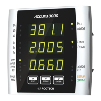
- Page 2 Digital Power Meter Accura 3000 front Accura 3000 rear...
- Page 3 Check the absence of voltage input using an appropriate voltage detection device. ◼ When powering the device, apply the appropriate rated voltage to the device. ◼ Install the device in a suitable electrical panel according to recommended installation instructions. ◼ ⓒ 2006 Rootech Inc. All Rights Reserved Page 3...
- Page 4 ◼ About the Manual Rootech Inc. reserves the right to make changes in the product specifications shown in this User Guide without prior notice. We recommend that customers should obtain the latest information on product specifications and the manual before placing orders.
- Page 5 Warranty Warranty Rootech Inc. provides a warranty for two years from the product receipt date, applicable only to the original purchaser of the products and software sold or licensed by the company To obtain warranty service, the purchased products should be free from serious defects in material and workmanship.
- Page 6 Warranty Accura 3000 User Guide Rootech Inc. shall not be liable for any claims other than those made by customers, including the original purchaser, their employees, agents, or contractors for any loss, damage, or expense incurred related to the purchased product when the above warranty terms and conditions are not fulfilled.
- Page 7 Accura 3000 User Guide Revision History Revision History The following versions of Accura 3000 User Guide have been released. Revision Date Description Revision 1.00 May 2, 2006 Initial release Revision 1.10 June 30, 2007 Revised installation steps and added warning sentences Revision 1.20...
-
Page 8: Table Of Contents
Full Screen in Display Mode ............................. 30 L-L Voltage Column....................................31 L-N Voltage Column ....................................32 Energy/Etc. Column ....................................33 Max. L-L Voltage Column ..................................34 Max. L-N Voltage Column ..................................34 Page 8 ⓒ 2006 Rootech Inc. All Rights Reserved... - Page 9 Energy ..........................................57 Appendix A Specifications ............................... 59 General Specifications ....................................59 Accura 3000 Digital Power Meter ............................... 59 Appendix B Standards ..............................62 IEC 61557-12:2018 Performance Measuring and Monitoring Devices(PMD) ..............63 IEC 62053-22:2020 Static Meters for AC Active Energy (Class 0.5S) ................. 65 IEC 62053-24:2020 Static Meters for Fundamental Reactive Energy (Class 0.5S) ............
- Page 10 Fig 2.21 Power Supply Wiring of Accura 3000..........................26 Fig 2.22 RS-485 Communication of Accura 3000 ........................27 Fig 2.23 Connecting Accura 3000 Devices for RS-485 Communication ................27 Fig 3.1 Front Panel of Accura 3000 ..............................28 Fig 3.2 Front Panel View ..................................29 Fig 3.3 Line-to-Line Voltage Display Screen ...........................
- Page 11 Fig 4.7 Vector Sum of the Total Apparent Power ........................54 Fig 4.8 Arithmetic Sum of the Total Apparent Power ........................ 55 Fig 4.9 PF Sign and PF Angle (Lead/Lag) ............................56 Fig 4.10 Demand Calculation................................. 57 ⓒ 2006 Rootech Inc. All Rights Reserved Page 11...
-
Page 12: Chapter 1 Introduction
Gapless Measurements of Voltage and Current : Average Values Available for 1-second Intervals Accura 3000 takes 512 voltage and 128 current samples per cycle and continuously provides average values for 1-second intervals, enabling real-time power analysis. Accurate Measurements of Voltage, Current, and Active Energy It has recently become essential to establish enterprise-wide energy management systems for efficient energy usage and preventive measures at sites such as plants, manufacturing factories, and buildings. -
Page 13: Product Information
Chapter 1 Introduction Product Information Accura 3000 meets the requirements for measurement accuracy class 0.2 as per IEC 61557-12 for voltage and current. It also meets the requirements for measurement accuracy classes 0.5 and 0.5S as per IEC 61557- 12 and IEC 62053-22 for active power and active energy, respectively. With high accuracy, Accura 3000 enables accurate analysis and diagnosis of problems with energy management at power facilities. -
Page 14: Chapter 2 Installation
Install the device in a dry location free from dirt, oil and corrosive vapors. There is no need to clean the device during installation. Page 14 ⓒ 2006 Rootech Inc. All Rights Reserved... -
Page 15: Product Appearance
Chapter 2 Installation Product Appearance Fig 2.1 Front Fig 2.2 Side Fig 2.3 Rear Components Fig 2.4 Components Accura 3000 Mounting wheel Protection cover and two Connector Short bar mounting screws ⓒ 2006 Rootech Inc. All Rights Reserved Page 15... -
Page 16: Dimensions
Chapter 2 Installation Accura 3000 User Guide Dimensions Fig 2.5 Front Fig 2.6 Side Fig 2.7 Rear Product Type Model Dimensions [mm] Weight Power meter Accura 3000 114.0 110.0 63.4 400 g Page 16 ⓒ 2006 Rootech Inc. All Rights Reserved... -
Page 17: Step 1: Installing The Device On The Panel
Chapter 2 Installation Step 1: Installing the Device on the Panel Accura 3000 is mounted at the front of a switchgear panel. ① Insert the meter into the cutout of the panel. (ANSI 4“ and DIN96 cutouts are supported.) ② Attach the mounting wheel to the back of the meter. -
Page 18: Step 2: Voltage/Current Wiring
If the voltage input gets out of the measurement range, it can affect accuracy. External PTs(Potential Transformers) should be used when measured voltages exceed the specified input voltage range. Caution When using external PTs, a fuse should be installed at the PT secondary. Page 18 ⓒ 2006 Rootech Inc. All Rights Reserved... -
Page 19: Current Input
Connect the ground terminal to the earth ground to protect the device from noise and surge. Failure to ◼ properly connect the chassis ground will void the warranty of the product. ⓒ 2006 Rootech Inc. All Rights Reserved Page 19... -
Page 20: Wiring Diagram Using External Pts
Fig 2.11 3P4W Connection with 3 PTs and 3 CTs Note Select “3P4U” from 「SETUP > Conn」 menus. Fig 2.12 3P3W Connection with 2 PTs and 3 CTs Note Select “3P3U” from 「SETUP > Conn」 menus. Page 20 ⓒ 2006 Rootech Inc. All Rights Reserved... -
Page 21: Fig 2.13 3P3W Connection With 2 Pts And 2 Cts
The L1 and L2 voltages should be connected to the V1 and V3 ports, and the N line should be connected to the VN port. Select “1P3U” from 「SETUP > Conn」 menus. ⓒ 2006 Rootech Inc. All Rights Reserved Page 21... -
Page 22: Fig 2.15 1P2W Connection With 1 Pt And 1 Ct
Fig 2.15 1P2W Connection with 1 PT and 1 CT Note The L1 voltage should be connected to the V port, and the N line should be connected to the V port. Select “1P2U” from 「SETUP > Conn」 menus. Page 22 ⓒ 2006 Rootech Inc. All Rights Reserved... -
Page 23: Wiring Diagrams Without Using External Pts
Fig 2.16 3P4W Direct Connection with 3 CTs Note Select “3P4U” from 「SETUP > Conn」 menus. Fig 2.17 3P3W Direct Connection with 3 CTs Note Select “3P3U” from 「SETUP > Conn」 menus. ⓒ 2006 Rootech Inc. All Rights Reserved Page 23... -
Page 24: Fig 2.18 3P3W Direct Connection With 2 Cts
The L1 and L2 voltages should be connected to the V and V ports, and the N line should be connected to the port. Select “1P3U” from 「SETUP > Conn」 menus. Page 24 ⓒ 2006 Rootech Inc. All Rights Reserved... -
Page 25: Fig 2.20 1P2W Direct Connection With 1 Ct
Fig 2.20 1P2W Direct Connection with 1 CT Note The L1 voltage should be connected to the V port, and the N line should be connected to the V port. Select “1P2U” from 「SETUP > Conn」 menus. ⓒ 2006 Rootech Inc. All Rights Reserved Page 25... -
Page 26: Step 3: Power Supply And Ground Wiring
Chapter 2 Installation Accura 3000 User Guide Step 3: Power Supply and Ground Wiring Fig 2.21 Power Supply Wiring of Accura 3000 Power Supply Wiring Item Description Port name L+, N- Connector type Screw-type terminal (pluggable) Wire specification 0.25 – 4.0 mm (24 –... -
Page 27: Step 4: Rs-485 Connection For External Communication
32 per bus 1. At 115,200 bps, a master can communicate with up to 16 slave devices at a maximum distance of 600 m. Fig 2.23 Connecting Accura 3000 Devices for RS-485 Communication * The shield wire of the RS-485 communication cable should be grounded at only one point to minimize noise due to loop current. -
Page 28: Chapter 3 Operation/Setup
Chapter 3 Operation/Setup Device Composition The front panel of Accura 3000 consists of the FND(Flexible Numeric Display) screen, which shows measurement and setup data, LEDs, and buttons used to control all operation modes. The device also has current and voltage input ports at the back and RS-485 communication ports for communication with the host system on the side. -
Page 29: Display Mode
Up(^) and Down(v) arrow buttons. The device’s circular navigation structure allows quick reversal between the first and the last screens using the Up(^) and Down(v) arrow buttons. ⓒ 2006 Rootech Inc. All Rights Reserved Page 29... -
Page 30: Full Screen In Display Mode
Accura 3000 User Guide Full Screen in Display Mode Accura 3000 displays measurement data on the voltage and current sensed by the device. Since MAX/MIN display settings are disabled by default, only the first three columns appear on the device's screen. If MAX/MIN display settings are enabled, the maximum/minimum values are displayed on the device's screen. -
Page 31: L-L Voltage Column
AB line-to-line voltage A-phase fundamental A-phase reactive FUND current power kVAR BC line-to-line voltage B-phase fundamental B-phase reactive FUND current power kVAR CA line-to-line voltage C-phase fundamental C-phase reactive FUND current power ⓒ 2006 Rootech Inc. All Rights Reserved Page 31... -
Page 32: L-N Voltage Column
B-phase voltage B-phase fundamental B-phase reactive FUND current power kVAR C-phase voltage C-phase C-phase reactive FUND fundamental current power Fig 3.3 Line-to-Line Voltage Display Screen Fig 3.4 Line-to-Neutral Voltage Display Screen Page 32 ⓒ 2006 Rootech Inc. All Rights Reserved... -
Page 33: Energy/Etc. Column
Fig 3.6 Power Factor Display Screen Fig 3.5 Energy Display Screen Fig 3.7 Frequency Display Screen Fig 3.8 Demand Display Screen ⓒ 2006 Rootech Inc. All Rights Reserved Page 33... -
Page 34: Max. L-L Voltage Column
B-phase reactive power kVAR FUND current C-phase voltage C-phase C-phase reactive kVAR FUND fundamental current power 1. The displayed values represent the maximum values of 1-second measurement data after resetting the MAX values. Page 34 ⓒ 2006 Rootech Inc. All Rights Reserved... -
Page 35: Min. L-L Voltage Column
C-phase C-phase FUND voltage fundamental current reactive power 1. The displayed values represent the minimum values of 1-second measurement data after resetting the MIN values. ⓒ 2006 Rootech Inc. All Rights Reserved Page 35... -
Page 36: Min. L-N Voltage Column
1. The displayed values represent the minimum values of 1-second measurement data after resetting the MIN values. Fig 3.11 Min. L-L Voltage Display Screen Fig 3.12 Min. L-N Voltage Display Screen Page 36 ⓒ 2006 Rootech Inc. All Rights Reserved... -
Page 37: Setup Mode
If there is no button operation during the setup timeout period in the setup mode or edit mode, the screen automatically returns to the display mode. The setup timeout period can be set via communication, and its default value is 10 minutes. ⓒ 2006 Rootech Inc. All Rights Reserved Page 37... -
Page 38: Full Screen In Setup Mode
Max/Min Display CT Rating Stop Bit Max/Min Max/Min Timeout Communication Demand Time Energy Demo Mode Address Calculation of Power Product Serial Per Phase Number Calculation of Total Hardware Version Power Firmware Version Page 38 ⓒ 2006 Rootech Inc. All Rights Reserved... -
Page 39: Measurement Setup
001 – 999 CT Rating Setup Description Default Ct (Current Transformer) Pr (Primary) CT Primary current rating [A] 50 A 00,001 – 99,999 Sc (Secondary) CT Secondary current rating [A] 01 – 99 ⓒ 2006 Rootech Inc. All Rights Reserved Page 39... - Page 40 The device supports two methods for calculating the total reactive power(Qt) and apparent power(St). Refer to 「Chapter 4 Measurements > Measurement Parameters > Total Power」. Setup Description Default tot UA CaLc (Total VA Calculation) UEct Vector sum method UEct ScaLa Arithmetic sum method Page 40 ⓒ 2006 Rootech Inc. All Rights Reserved...
-
Page 41: Rs-485 Communication Setup
StoP (Stop bit) 1-bit 1-bit 2-bit Communication Address Setup Description Default Addr (Address) 0 – 247 Communication address 1. The address should be set to a non-zero value for normal communication. ⓒ 2006 Rootech Inc. All Rights Reserved Page 41... -
Page 42: Reset Setup
Resets demand values Peak Demand Reset Setup Description Default PEak dMd (Peak Demand) rESEt Resets peak demand values Max/Min Reset Setup Description Default Max Min (Maximum Minimum) rESEt Resets the maximum/minimum values Page 42 ⓒ 2006 Rootech Inc. All Rights Reserved... -
Page 43: Additional Setup & Info
Max/Min Display Timeout Setup Description Default Max (Max/Min display timeout) 1 − 60 Timeout period for displaying the 10 minutes maximum/minimum values [min] Cont The maximum/minimum values continue to be displayed. ⓒ 2006 Rootech Inc. All Rights Reserved Page 43... - Page 44 [d].[d][d] PCB version 5A_[d][d] Hardware revision of the product 1. [d] → decimal Firmware Version Setup Description Default F.uEr (Firmware Version) [d].[d].[d][d][d] Firmware version of the product 1. [d] → decimal Page 44 ⓒ 2006 Rootech Inc. All Rights Reserved...
-
Page 45: Necessary Steps For Device Setup
Chapter 3 Operation/Setup Necessary Steps for Device Setup For normal operation of Accura 3000, the following steps for device setup should be taken. Connection Mode The connection mode is set to 3P4U by default. Thus, if you want to set the connection... -
Page 46: Chapter 4 Measurements
Chapter 4 Measurements Voltage/Current Sampling Voltage Sensing In Accura 3000 module, voltages drop due to the distribution of resistance, and voltage values are converted to ADC values through an AAF(Anti-aliasing Filter). Fig 4.1 Voltage Sensing and Signal Processing Current Sensing In Accura 3000 module, current values are converted through a CT(Current Transformer) and then converted to ADC values through an AAF(Anti-aliasing Filter). -
Page 47: Calculation Of Measurement Data
Chapter 4 Measurements Calculation of Measurement Data Measurement Parameters The following table shows the measurement parameters of Accura 3000. Some parameters are available only via communication. The maximum and minimum values provided by the device represent the maximum and minimum values of measured data after they have been reset. -
Page 48: Voltage Wiring
– V The following measurement data are provided. Item L-N Voltage (RMS) L-L Voltage (RMS) Current (RMS) Active Power A Phase * PF B Phase * PF C Phase * PF Average/Total Page 48 ⓒ 2006 Rootech Inc. All Rights Reserved... -
Page 49: Fig 4.4 3P3W Connection With 2 Pts And 3 Cts
3-Phase 3-Wire(3P3W) Connection In 3P3W mode, the voltage wiring method differs according to the number of PTs(Potential Transformer) used in the wiring configuration. However, Accura 3000 measures voltage signals in the same way regardless of the wiring method. Fig 4.4 3P3W Connection with 2 PTs and 3 CTs The method of measuring voltage is as follows. - Page 50 However, by using a virtual neutral point where the residual voltage value(V ) of three phase voltages becomes zero, voltage and power values per phase can be calculated. Page 50 ⓒ 2006 Rootech Inc. All Rights Reserved...
-
Page 51: Fig 4.5 1P3W Connection With 2Pts And 2Cts
– V – V The following measurement data are provided. Item L-N Voltage (RMS) L-L Voltage (RMS) Current (RMS) Active Power A phase * PF B phase C phase * PF Average/Total ⓒ 2006 Rootech Inc. All Rights Reserved Page 51... -
Page 52: Fig 4.6 1P2W Connection With 1 Pt And 1 Ct
= 0 (The value becomes 0 in 1P2W mode.) the device ) The following measurement data are provided. Item Voltage (RMS) Current (RMS) Active Power A phase * PF B phase C phase Average/Total Page 52 ⓒ 2006 Rootech Inc. All Rights Reserved... -
Page 53: Power Per Phase
The sign of the reactive power corresponds to that of the reactive power calculated based on fundamental frequency components. = ± √ �� �� − �� �� �� �� ⓒ 2006 Rootech Inc. All Rights Reserved Page 53... -
Page 54: Total Three-Phase Power
The total apparent power is calculated based on the vector sum of the total active power and reactive power. �� = √ �� + �� �� �� �� Fig 4.7 Vector Sum of the Total Apparent Power | St | Page 54 ⓒ 2006 Rootech Inc. All Rights Reserved... -
Page 55: Fig 4.8 Arithmetic Sum Of The Total Apparent Power
= ± √ �� �� − �� �� �� �� Fig 4.8 Arithmetic Sum of the Total Apparent Power | St | ⓒ 2006 Rootech Inc. All Rights Reserved Page 55... -
Page 56: Power Factor(Pf)
4 quadrants. When reactive power(Q) is 0, it is in neither a Lead nor a Lag status. Fig 4.9 PF Sign and PF Angle (Lead/Lag) Page 56 ⓒ 2006 Rootech Inc. All Rights Reserved... -
Page 57: Demand
Sum(Total) energy is obtained by adding delivered energy to received energy. Net energy is obtained by subtracting delivered energy from received energy. Type of Energy Active Energy per Phase Received 123 kWh Delivered 11 kWh 134 kWh 112 kWh ⓒ 2006 Rootech Inc. All Rights Reserved Page 57... - Page 58 Negative reactive energy for each phase Accumulated value of negative 0 – (2 kVARh reactive power for each phase Apparent energy for each phase Accumulated value of apparent 0 – (2 kVAh power for each phase Page 58 ⓒ 2006 Rootech Inc. All Rights Reserved...
-
Page 59: Appendix A Specifications
Sampling rate 512 samples/cycle Measuring range 50 – 277 V L-N (accuracy guaranteed) 87 – 480 V L-L (for unearthed Delta & Y systems) Accuracy ±0.2 % Reading IEC 61557-12 Class 0.2 ⓒ 2006 Rootech Inc. All Rights Reserved Page 59... - Page 60 Power consumption Inrush current Peak 31 A, duration no more than 1 msec (AC 220 V) Peak 11 A, duration no more than 200 μsec (DC 110 V) General Weight 400 g Page 60 ⓒ 2006 Rootech Inc. All Rights Reserved...
- Page 61 6. The device conforms to UL standards for the tested AC power supply voltage. 7. When installing fuses on the power input line, it is recommended to use UL listed Class RK5 fuses above 2 A/500 V. ⓒ 2006 Rootech Inc. All Rights Reserved Page 61...
-
Page 62: Appendix B Standards
UL 61010-1 3rd edition, UL 61010-2-030 2nd edition EN 55011:2016/A11:2020, EN IEC 61326-1:2021, EN IEC 61326-2-1:2021, EN IEC 61000-3-2:2019/A1:2021, EN 61000-3-3:2013/A2:2021 EN 55011:2016/A11:2020, EN IEC 61326-1:2021, EN IEC 61326-2-1:2021 General Warranty period 2 years Page 62 ⓒ 2006 Rootech Inc. All Rights Reserved... -
Page 63: Iec 61557-12:2018 Performance Measuring And Monitoring Devices(Pmd)
Current Range Min. Bandwidth Crest Factor Class 0.2 (Harmonic) PMD Sx 10 %In – Imax. 45 Hz to 15 times ±0.2 % the rated frequency PMD Dx 20 %Ib – Imax. ⓒ 2006 Rootech Inc. All Rights Reserved Page 63... - Page 64 Class 0.5 PMD Dx PMD Sx 50 %Un – Umax. 20 %Ib – Imax. 10 %In – Imax. 0.5 inductive ±0.005 – 0.8 capacitive 1. It indicates a value without a unit. Page 64 ⓒ 2006 Rootech Inc. All Rights Reserved...
-
Page 65: Iec 62053-22:2020 Static Meters For Ac Active Energy (Class 0.5S)
– Imax ±0.5 % 5 %In – 10 %In ±1.0 % 10 %In – Imax ±0.5 % 0.25 ±1.0 % 1. Un indicates the rated voltage, and In indicates the rated current. ⓒ 2006 Rootech Inc. All Rights Reserved Page 65... -
Page 66: Appendix C Accuracy/Reliability
Appendix C Accuracy/Reliability Accura 3000 User Guide Appendix C Accuracy/Reliability Accuracy Measurement by Accura 3000 Accura 3000 meets measurement accuracy in a range broader than the measuring range required for the IEC 61557-12 standard. Parameter Accuracy Measuring Range (Accuracy Guaranteed) / Min. -
Page 67: Appendix D Ordering Information
Accura 3000 User Guide Appendix D Ordering Information Appendix D Ordering Information Product Type Model Description Digital Power Meter Accura 3000 Measures voltage, current, power, and energy Supports RS-485 communication ⓒ 2006 Rootech Inc. All Rights Reserved Page 67... - Page 68 Accura 2300/2350, Accura 2300S/2350, Accura 2300S/2350-1P3FSC, Accura 2500/2550, Accura 2700/2750, Accura 3000, Accura 3300E, Accura 3500/3550/3500E, Accura 3700, Accura 5500, and Accura 7500 are trademarks of Rootech Inc. Contact us for detailed product specifications and ordering information. Information contained herein is subject to change without...
Need help?
Do you have a question about the ACCURA 3000 and is the answer not in the manual?
Questions and answers