ROOTECH ACCURA 3300E User Manual
High accuracy digital power meter
Hide thumbs
Also See for ACCURA 3300E:
- User manual (88 pages) ,
- Quick setup manual (13 pages) ,
- User manual (88 pages)
Table of Contents
Advertisement
Quick Links
Advertisement
Table of Contents

Related Manuals for ROOTECH ACCURA 3300E


Summary of Contents for ROOTECH ACCURA 3300E
- Page 2 ◼ including removing PT fuses and shorting CT secondaries. Install the product in enclosures or a similar cabinet to prevent access to the terminal strips of the ◼ product after wiring. Page 2 ⓒ 2015 Rootech Inc. All Rights Reserved...
- Page 3 Failure to properly connect the chassis ground will void the warranty of the product. About the Manual Rootech Inc. reserves the right to make changes in the product specifications shown in this User Guide without prior notice. We recommend that customers should obtain the latest information on product specifications and the manual before making orders.
- Page 4 Rootech will decide at its discretion whether to repair or replace it or give a refund for the product for when the warranty period for the product expired or issues related to the product are not applicable for warranty terms and conditions.
- Page 5 Accura 3300E User Guide Warranty Rootech shall not be liable for any other claims except the claims made by customers, including the original purchaser, his employees, agents, or contractors for any loss, damage, or expense incurred related to the purchased product when the above warranty terms and conditions are not fulfilled.
- Page 6 Revision History Accura 3300E User Guide Revision History The following versions of the Accura 3300E User Guide have been released. Revision Date Description Revision 1.00 December 4, 2015 Initial release Revision 1.01 February 20, 2016 The following wording “the description of the temperature”...
-
Page 7: Table Of Contents
Current Input ..........................................19 Wiring Considerations ......................................20 Wiring Diagram Using External PTs ..................................21 Step 3: Wiring Accura 3300E for External Communication ..........................27 RS-485 Communication ......................................27 Step 4: Power Supply and Ground Wiring................................. 28 Power Supply Wiring ........................................ 28 Ground Wiring .......................................... - Page 8 IEC 62053-24:2020 Static Meters for Fundamental Reactive Energy (Class 0.5S) ................84 IEC 61557-12:2018 Performance Measuring and Monitoring Devices(PMD) ................... 84 Appendix C Accuracy/Reliability ................................87 Accuracy ............................................87 Reliability ............................................88 Appendix D Ordering Information ............................... 89 Page 8 ⓒ 2015 Rootech Inc. All Rights Reserved...
- Page 9 Wiring Mode(Conn) = 1P2U ................................. 26 Fig 2.20 RS-485 Communication of Accura 3300E ........................27 Fig 2.21 Connecting Accura 3300E Devices for RS-485 Communication ............... 27 Fig 2.23 Power Supply Wiring of Accura 3300E .......................... 28 Fig 3.1 Front Panel of Accura 3300E ..............................29 Fig 3.2 Screen in Display Mode ................................
- Page 10 Fig 4.9 Demand Calculation .................................. 77 Fig 4.10 Predicted Demand Calculation ............................78 Fig 4.11 Hourly Auto Sync ..................................79 Fig 4.12 Manual Sync ....................................79 Fig 4.11 Symmetrical Components ..............................80 Page 10 ⓒ 2015 Rootech Inc. All Rights Reserved...
-
Page 11: Chapter 1 Introduction
Proven Safety and Reliability with CE/UL/KC Certifications The internal and external structures (product and circuit design) of Accura 3300E meet safety and reliability requirements for CE(EN 55011: 2016/A11:2020, EN IEC 61326-1:2021, EN IEC 61326-2-1:2021, EN IEC 61000- 3-2:2019/A1:2021, EN 61000-3-3:2013/A2:2021), UL(UL 61010-1 3rd edition, IEC 61010-2-030 2nd edition), and KC(EN 55011: 2016/A11:2020, EN IEC 61326-1:2021, EN IEC 61326-2-1:2021) standards. -
Page 12: Product Information
Product Features Accura 3300E Digital Power Meter Accura 3300E has ±0.2 % of reading accuracy for voltage and current measurements and meets IEC 62053- 22 Class 0.5S standards for power and energy measurements. It also provides various information including harmonics(up to the 50th order), Crest factor, K-factor, and unbalance. which are essential for power quality management of switchgear panels. - Page 13 10. At 115,200 bps, a master can communicate with up to 16 slave devices, and the maximum distance between the master and the slave is 600 m 11. The device conforms to UL standards for the tested AC power supply voltage. ⓒ 2015 Rootech Inc. All Rights Reserved Page 13...
-
Page 14: Chapter 2 Installation
Accura 3300E User Guide Chapter 2 Installation Environmental Conditions Accura 3300E should be mounted in a dry, dirt free location away from heat sources and very high electric fields. To operate the product properly, environmental conditions as below should be considered. Environmental Conditions... -
Page 15: Before Installation
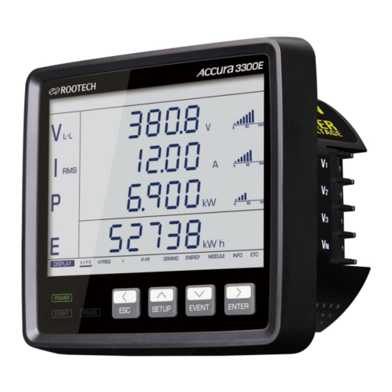
Accura 3300E User Guide Chapter 2 Installation Before Installation Before installing the Accura 3300E, observe the following instructions and safety precautions. Caution You should power up the device after voltage and current wiring is completed. Product Appearance Fig 2.1 Accura 3300E Front Fig 2.2 Accura 3300E Side... -
Page 16: Components
Fig 2.4 Accura 3300E Components Accura 3300E Four washers/four nuts Rear protection cover Short bar Connector Dimensions Fig 2.5 Accura 3300E Front Dimensions Fig 2.6 Accura 3300E Side Dimensions Fig 2.7 Accura 3300E Rear Dimensions Product Dimensions Device Type Model Dimensions [mm]... -
Page 17: Step 1: Installation
Accura 3300E is mounted at the front of the switchgear panel. ① Insert the meter into the panel cutout. ② Attach the connector to the side of Accura 3300E and then secure the meter to the panel using mounting nuts and washers. -
Page 18: Step 2: Voltage/Current Wiring
If the voltage input gets out of the measurement range, it can affect accuracy. External PTs(Potential Transformers) should be used when measured voltages exceed the specified input voltage range. Caution When using external PTs, a fuse should be installed at the PT secondary. Page 18 ⓒ 2015 Rootech Inc. All Rights Reserved... -
Page 19: Current Input
1. The maximum screw tightening torque of the barrier-type terminal block is 1.4 Nm(14 kgf-cm, 12 Ibf-in). 2. When connecting wires to the terminal block, use UL listed lugs. 3. The rated current In is 5 A. 4. The rated current In is 1 A. ⓒ 2015 Rootech Inc. All Rights Reserved Page 19... -
Page 20: Wiring Considerations
Connect the ground terminal to the earth ground to protect the device from noise and surge. Failure ◼ to properly connect the chassis ground will void the warranty of the product. Page 20 ⓒ 2015 Rootech Inc. All Rights Reserved... -
Page 21: Wiring Diagram Using External Pts
- When there is the primary current of the CT, opening the CT secondary can cause serious accidents resulting from high voltages. - When wiring devices without a CT, you should follow the guidelines provided by Rootech. Fig 2.10 3P4W Connection with 3 PTs and 3 CTs, Wiring Mode(Conn)= 3P4U Note Select “3P4U”... -
Page 22: Fig 2.11 3P3W Connection With 2 Pts And 3 Cts
Select “3P3U” from the “Wiring Mode” setup menus. Fig 2.12 3P3W Connection with 2 PTs and 2 CTs, Wiring Mode(Conn) = 3P3U Note Select “3P3U” from the “Wiring Mode” setup menus. Page 22 ⓒ 2015 Rootech Inc. All Rights Reserved... -
Page 23: Fig 2.13 1P3W Connection With 2 Pts And 2 Cts
Select “1P3U” from the “Wiring Mode” setup menus. Fig 2.14 1P2W Connection with 1 PT and 1 CT, Wiring Mode(Conn) = 1P2U Note and V terminals should be used. Select “1P2U” from the “Wiring Mode” setup menus. ⓒ 2015 Rootech Inc. All Rights Reserved Page 23... -
Page 24: Fig 2.15 3P4W Direct Connection With 3 Cts
Fig 2.15 3P4W Direct Connection with 3 CTs, Wiring Mode(Conn) = 3P4U Note Select “3P4U” from the “Wiring Mode” setup menus. Fig 2.16 3P3W Direct Connection with 3 CTs, Wiring Mode(Conn) = 3P3U Note Select “3P3U” from the “Wiring Mode” setup menus. Page 24 ⓒ 2015 Rootech Inc. All Rights Reserved... -
Page 25: Fig 2.17 3P3W Direct Connection With 2 Cts
Fig 2.17 3P3W Direct Connection with 2 CTs, Wiring Mode(Conn) = 3P3U Note Select “3P3U” from the “Wiring Mode” setup menus. Fig 2.18 1P3W Direct Connection with 2 CTs, Wiring Mode(Conn) = 1P3U Note Select “1P3U” from the “Wiring Mode” setup menus. ⓒ 2015 Rootech Inc. All Rights Reserved Page 25... -
Page 26: Fig 2.19 1P2W Direct Connection With 1 Ct
Accura 3300E User Guide Fig 2.19 1P2W Direct Connection with 1 CT, Wiring Mode(Conn) = 1P2U Note and V terminals should be used. Select “1P2U” from the “Wiring Mode” setup menus. Page 26 ⓒ 2015 Rootech Inc. All Rights Reserved... -
Page 27: Step 3: Wiring Accura 3300E For External Communication
1. At 115,200 bps, a master can communicate with up to 16 slave devices, and the maximum distance between the master and the slave is 600 m. Fig 2.21 Connecting Accura 3300E Devices for RS-485 Communication * To minimize noise caused by ground loops, a shielded cable should be grounded at only one end as shown in the figure. -
Page 28: Step 4: Power Supply And Ground Wiring
Chapter 2 Installation Accura 3300E User Guide Step 4: Power Supply and Ground Wiring Fig 2.23 Power Supply Wiring of Accura 3300E Power Supply Wiring Item Description Port name L+, N- Connector type Screw-type terminal (pluggable) Wire specification 0.25 – 4.0 mm (24 –... -
Page 29: Chapter 3 Operation/Setup
Chapter 3 Operation/Setup Chapter 3 Operation/Setup The front panel of Accura 3300E consists of the 4.7” LCD screen which shows measurement and setup data, three LEDs which display power supply and communication status, and four buttons used to select all operation modes. -
Page 30: Fig 3.2 Screen In Display Mode
Even when an event does not occur, you can check the event logs by long pressing the EVENT button. In the event mode, the “Event” segment in the top menu bar lights up. Page 30 ⓒ 2015 Rootech Inc. All Rights Reserved... -
Page 31: Fig 3.4 Screen In Event Mode
“DISPLAY” to “SETUP”. When an event occurs, the backlight of the LCD screen blinks. The LCD backlight timeout is 5 seconds by default, and users can set it to a value up to 9,999 minutes. ⓒ 2015 Rootech Inc. All Rights Reserved Page 31... - Page 32 If there is no button operation for 1 minute in the edit mode, the screen automatically returns to the setup mode. 1. It can be set via communication, and the default value is 10 minutes. Page 32 ⓒ 2015 Rootech Inc. All Rights Reserved...
-
Page 33: Display Mode
Accura 3300E User Guide Chapter 3 Operation/Setup DISPLAY Mode Front View Displayed segments on the screen may differ according to the hardware version of Accura 3300E. However, displayed parameters are the same. Fig 3.5 Accura 3300E Front View Voltage Current... - Page 34 Setup for events COMM Setup for RS-485 communication RESET Setup for the reset function DISPLAY Setup for the LCD display Meter information such as serial number, version, etc. G: Unit H: Graph Page 34 ⓒ 2015 Rootech Inc. All Rights Reserved...
-
Page 35: Display Screen
Accura 3300E User Guide Chapter 3 Operation/Setup Display Screen Accura 3300E displays information on measurement parameters. ⓒ 2015 Rootech Inc. All Rights Reserved Page 35... -
Page 36: Measurement Parameter Display Screen
This screen displays the total energy value with nine digits appearing in the third and the fourth lines. Fig 3.7 Last Screen Appearing in the First Column of DISPLAY Mode Page 36 ⓒ 2015 Rootech Inc. All Rights Reserved... -
Page 37: Fig 3.8 Line-To-Line Voltage Display Screen
THD, current TDD, residual current, zero-sequence/negative-sequence unbalance, and unbalance according to the NEMA standard in sequence. If you press the Up[v] arrow button, you can see measured values in reverse order. Fig 3.9 Phase Current Display Screen ⓒ 2015 Rootech Inc. All Rights Reserved Page 37... -
Page 38: Fig 3.10 Power Display Screen
By pressing the Down[v] arrow button, you can check demand current, the maximum demand active power and demand current values in sequence. If you press the Up[v] arrow button, you can see measured values in reverse order. Fig 3.11 Demand Active Power Screen Page 38 ⓒ 2015 Rootech Inc. All Rights Reserved... -
Page 39: Fig 3.12 Net Energy Display Screen On The Energy Display Screen
Fig 3.12 Net Energy Display Screen on the Energy Display Screen By pressing the Right[>] arrow button again on the energy display screen, you can navigate to the ETC screen. The ETC screen displays the temperature of Accura 3300E measured by the temperature sensor integrated into the MCU. -
Page 40: Event Mode
Event Mode Generation of Event Alarms Accura 3300E provides event alarms when the device detects events such as fuse fail, phase open, blackout, and over-temperature events. When an alarm is generated, the LCD backlight and the EVENT LED at the bottom left side of the device blink. -
Page 41: Fig 3.14 Example Of Event Log Number
Last event log number Last event log number 1. Event log numbers are as follows. Event Log number N – 49 Oldest saved event Event Log number N Latest saved event ⓒ 2015 Rootech Inc. All Rights Reserved Page 41... - Page 42 B PHSE (Phase) The phase where the event occurs (B phase OPEn (Open) Phase open 1. d → decimal number 2. The phase(A, B, C) where the event occurs is displayed. Page 42 ⓒ 2015 Rootech Inc. All Rights Reserved...
- Page 43 Over-Temperature Event Log It displays the information when an over-temperature event occurs. Display E[Event] Event number [d][d][d] 000 – 999 tEnP (Temperature) An over-temperature event occurs. OvEr (Over) 1. d → decimal number ⓒ 2015 Rootech Inc. All Rights Reserved Page 43...
-
Page 44: Setup Mode
Accura 3300E User Guide SETUP Mode To set the wiring mode, PT rating, RS-485 communication, and events of Accura 3300E and check setup data, you should enter the setup mode by long pressing the SETUP button. In the setup mode, you can check and change setup data with the Left[<]/Up[^]/Down[v]/Right[>] arrow, ESC, and ENTER buttons. -
Page 45: Meter Setup
Pr[Primary] Primary voltage(line-to-line) rating of the PT [d][d][d][d][d][d] 000001 – 999999 [default 380] Sc[Secondary] Secondary voltage(line-to-line) rating of the PT [d][d][d] 001 – 999 [default 380] 1. d → decimal number ⓒ 2015 Rootech Inc. All Rights Reserved Page 45... - Page 46 The reference current is used as the reference value for bar graphs displayed on the screen and TDD configurations. Setup Range Pr[Primary] Reference current on the primary side of the CT [d][d][d][d][d].[d] 00000.1 – 99999.9 [default 50.0] Accura 3300E-5A [default 10.0] Accura 3300E-1A 1. d → decimal number Page 46 ⓒ 2015 Rootech Inc. All Rights Reserved...
- Page 47 1 – 60 minute [default 15] Number of Demand Subintervals (dMd → Demand, noSb → Number of Demand Subintervals) Accura 3300E uses the “sliding window” method to calculate demand values. Demand time[minute] = demand subinterval x number of demand subintervals E.g.) In Korea(15-minute demand period), the demand subinterval is 15 minutes, and the number of...
- Page 48 Calculation of Total Power (tot VA CaLc → Total VA Calculation) Accura 3300E supports two methods for the calculation of the total power based on the power per phase. One method is to calculate the total power based on the vector sum of the apparent power, and the other is to calculate the total power based on the arithmetic sum of three-phase apparent power vectors.
- Page 49 CT. When configuring the minimum measured value as 20 mA(default value) in the Accura 3300E-5A model, any value no more than 1/250 of the rating would be displayed as 0 when it is connected to the CT with a secondary current rating of 5 A.
- Page 50 However, if it is set to “Off”, the sign of reactive power is not displayed. Setup Range on[ON, default] Sign of reactive power is displayed. oFF[OFF] Sign of reactive power is not displayed. Page 50 ⓒ 2015 Rootech Inc. All Rights Reserved...
- Page 51 3, respectively. P [Positive, default] Normal current flow from the Source(S) to the Load(L) N [Negative] Reverse current flow from the Load(L) to the Source(S) 1. d → decimal number ⓒ 2015 Rootech Inc. All Rights Reserved Page 51...
-
Page 52: Event Setup
When the measured voltage and current values for all phases are zero, it is deemed that a blackout event occurs. Setup Range Phase open and blackout event detection enabled oFF[default] Phase open and blackout event detection disabled Page 52 ⓒ 2015 Rootech Inc. All Rights Reserved... - Page 53 Start threshold of an over-temperature event [default 50] End Threshold of Over-Temperature Event (tnP.E → Temperature End) Setup Range – (start End threshold of an over-temperature event threshold -1) ℃ [default 48] ⓒ 2015 Rootech Inc. All Rights Reserved Page 53...
-
Page 54: Rs-485 Communication Setup
Parity Bit (Prty → Parity Bit) Setup Range EuEn [default] Even parity nonE No parity Odd parity Stop Bit (StoP→ Stop Bit) Setup Range 1 [default] 1 stop bit 2 stop bits Page 54 ⓒ 2015 Rootech Inc. All Rights Reserved... - Page 55 In order to read measurement data via communication, the device address should be set to a valid value not zero. Setup Range – 0, 1 [d][d][d] [default 0] 1. d → decimal number ⓒ 2015 Rootech Inc. All Rights Reserved Page 55...
-
Page 56: Reset Setup
Maximum/Minimum Reset (MaH → Maximum, Min → Minimum) The maximum and minimum demand values are reset with the reset function for the maximum/minimum values. Setup Range Resets the maximum/minimum values rESEt [Reset] Page 56 ⓒ 2015 Rootech Inc. All Rights Reserved... - Page 57 Accura 3300E User Guide Chapter 3 Operation/Setup Energy Reset (Enrg → Energy) Setup Range Resets energy[kWh, kVARh, kVAh] values rESEt (Reset) All Reset Setup Range rESEt (Reset) Resets all parameters (demand, maximum/minimum, energy) ⓒ 2015 Rootech Inc. All Rights Reserved Page 57...
-
Page 58: Display Setup
[default 60] In order to save power consumption, the brightness of the LCD backlight changes to the configured low brightness value after the button is last pressed and the configured time passes. Page 58 ⓒ 2015 Rootech Inc. All Rights Reserved... - Page 59 The backlight brightness changes from the set High value to the set Medium value after the button is last pressed and a certain time passes. After changing to the set Medium value, brightness is gradually diminished to the set Low value. ⓒ 2015 Rootech Inc. All Rights Reserved Page 59...
- Page 60 When the PT ratio changes, it provides the voltage proportional to the PT ratio. Unbalance Provides an unbalanced Phase angle of the 3 phase condition voltage per phase: 0°, -128.4°, 111.6° Page 60 ⓒ 2015 Rootech Inc. All Rights Reserved...
-
Page 61: Info/Etc Setup
Hardware revision of the product [d].[d][d] CT type (Accura 3300E-5A/1A) Ct_[d]A 1. d → decimal number Firmware Version (FUEr → Firmware Version) Setup Range Firmware version of the product [d].[d][d] 1. d → decimal number ⓒ 2015 Rootech Inc. All Rights Reserved Page 61... - Page 62 Chapter 3 Operation/Setup Accura 3300E User Guide Bootloader Version (bUEr → Bootloader Version) Setup Range Bootloader version of the product (d).(d).(d)(d)(d) 1. d → decimal number Page 62 ⓒ 2015 Rootech Inc. All Rights Reserved...
-
Page 63: Necessary Steps For Device Setup
Chapter 3 Operation/Setup Necessary Steps for Device Setup For normal operation of Accura 3300E, the following steps for device setup should be taken. Connection Mode (Conn → Connection] The connection mode is set to 3-phase 4-wire by default. Thus, in 3P4W mode, skip the following steps(2, 3, 4, 5). - Page 64 3. The primary and secondary current ratings of the CT are used to determine the ratio only for measuring the current. 4. It is used as the reference value for the bar graph displayed on the screen Page 64 ⓒ 2015 Rootech Inc. All Rights Reserved...
-
Page 65: Chapter 4 Measurements
The maximum and minimum values the device provides after resetting the values are stored in non-volatile memory. Thus, the data are maintained even when Accura 3300E is turned off and then on. Peak demand values are reset to zero by resetting the maximum/minimum values not demand values. - Page 66 (DC, 1 – 50 Magnitude of Current Harmonics ▲ (DC, 1 - 50 2 cycles of voltage waveforms Instantaneous ▲ waveform (64 samples/cycle) 2 cycles of current waveforms ▲ (64 samples/cycle) Page 66 ⓒ 2015 Rootech Inc. All Rights Reserved...
-
Page 67: Measurement Event Parameters
RMS current obtained by summing the three-phase currents in the time domain. Measurement Event Parameters The following table shows the parameters of the measurement events provided via Accura 3300E and communication. You can check detailed information on the last 50 events through event logs. In the event mode, the “Event”... -
Page 68: Measurements According To Voltage Wiring Modes
: Voltage of connected N terminal Available Measurement Values Item L-N Voltage [rms] L-L Voltage [rms] Current [rms] Active Power A Phase (I1) * PF B Phase (I2) * PF C Phase (I3) * PF Average/Total Page 68 ⓒ 2015 Rootech Inc. All Rights Reserved... -
Page 69: 3-Phase 3-Wire Connection
You can use 2 or 3 PTs(Potential Transformers) in 3-phase 3-wire mode. Its installation cost differs according to the number of PTs. However, regardless of how many PTs are used, Accura 3300E measures voltage signals in the same way. By using 3 CTs, you can measure the residual current by summing three-phase current values. - Page 70 However, by using a virtual neutral point where the residual voltage value of the three phase voltages becomes zero, voltage and power values for each phase can be calculated. Page 70 ⓒ 2015 Rootech Inc. All Rights Reserved...
-
Page 71: 1-Phase 3-Wire Connection
= V3 – V1 Available Measurement Values Item L-N Voltage [rms] L-L Voltage [rms] Current [rms] Active Power Phase A (I1) * PF Phase B Phase C (I3) * PF Average/Total ⓒ 2015 Rootech Inc. All Rights Reserved Page 71... -
Page 72: 1-Phase 2-Wire Connection
= 0 (The value becomes 0 in 1P2W mode.) Available Measurement Values Item L-N Voltage [rms] L-L Voltage [rms] Current [rms] Active Power A Phase (I1) * PF B Phase C Phase Average/Total Page 72 ⓒ 2015 Rootech Inc. All Rights Reserved... -
Page 73: Measurement Of Power Per Phase
�� = ±√�� − �� �� = ±√�� − �� �� = ±√�� − �� �� �� �� �� �� �� �� �� �� ⓒ 2015 Rootech Inc. All Rights Reserved Page 73... -
Page 74: Three-Phase Power Measurement
The total apparent power is calculated based on the vector sum of the total active power and total reactive power. �� = √�� + �� (Vector sum) �� �� �� Fig 4.6 Vector Sum for the Total Apparent Power | St | Page 74 ⓒ 2015 Rootech Inc. All Rights Reserved... -
Page 75: Arithmetic Sum Calculation
= ± √ �� �� − �� �� �� �� Fig 4.7 Arithmetic Sum for the Total Apparent Power | St | ⓒ 2015 Rootech Inc. All Rights Reserved Page 75... -
Page 76: Power Factor(Pf) Measurement
If the current leads or lags the voltage by a phase angle, the power factor is displayed as LEAD or LAG on the screen on the front of Accura 3300E. If the reactive power is zero, the information is not displayed. -
Page 77: Demand Measurement
100 − (��ℎ���������� ���������������� ����������) ∙ 60 [ ������ ] �� = ∙ �� ������ If the thermal time constant τ is less than 1 second, it is calculated as 1 second. ⓒ 2015 Rootech Inc. All Rights Reserved Page 77... -
Page 78: Predicted Demand
Fig 4.10 Predicted Demand Calculation Demand Sync Accura 3300E supports two methods for synchronizing the starting time of a demand subinterval. 1) Hourly Auto Sync: refers to automatically synchronizing the starting time of a demand subinterval every hour. 2) Manual Sync: refers to synchronizing the starting time of a demand subinterval at the time users issue a sync command. -
Page 79: Fig 4.11 Hourly Auto Sync
Fig 4.12 Manual Sync source input Demand Time (T =15 min) Avg 4.3 Avg 4.7 Avg 2.9 Avg 3.4 Avg 3.2 1:00 1:04 1:09 1:14 1:19 1:59 2:04 2:09 time Manual sync command ⓒ 2015 Rootech Inc. All Rights Reserved Page 79... -
Page 80: Unbalance(Nema Mg1)
Zero-sequence, positive-sequence, and negative-sequence components are calculated with the following equation. �� �� �� 2�� ��∙ �� �� ∙ [ ] ∙ [ ] , ��ℎ������ �� = �� �� �� �� �� �� 1 �� �� �� Page 80 ⓒ 2015 Rootech Inc. All Rights Reserved... -
Page 81: Negative-Sequence Unbalance
���������������� ���������������� ������������������ ���������� = × 100 [%] �� Zero-Sequence Unbalance It is the ratio between the magnitudes of the zero-sequence component and the positive-sequence component. �� �������� ���������������� ������������������ = × 100 [%] �� ⓒ 2015 Rootech Inc. All Rights Reserved Page 81... -
Page 82: Appendix A Specifications
Ingress protection against dust IEC 60529 IP54 (Accura 3300E) and water 1. The device conforms to UL standards for the tested AC power supply voltage. 2. Compliant with UL 61010-1(3rd edition) Page 82 ⓒ 2015 Rootech Inc. All Rights Reserved... -
Page 83: Appendix B Standard
UL 61010-1 3rd edition, UL 61010-2-030 2nd edition EN 55011:2016/A11:2020, EN IEC 61326-1:2021, EN IEC 61326-2-1:2021, EN IEC 61000-3-2:2019/A1:2021, EN 61000-3-3:2013/A2:2021 EN 55011:2016/A11:2020, EN IEC 61326-1:2021, EN IEC 61326-2-1:2021 General Warranty period 2 years ⓒ 2015 Rootech Inc. All Rights Reserved Page 83... -
Page 84: Iec 62053-22:2020 Static Meters For Ac Active Energy (Class 0.5S)
2 % In – 10 % In 0.5 inductive ±1.0 % 0.8 capacitive ±1.0 % 20 % Ib – Imax 10 % In – Imax 0.5 inductive ±0.6 % 0.8 capacitive ±0.6 % Page 84 ⓒ 2015 Rootech Inc. All Rights Reserved... - Page 85 10 % In – Imax 45 Hz to 15 times ±0.2 % rated frequency PMD Dx 20 % Ib – Imax 1. Uncertainty is indicated as a percentage of the largest phase current value. ⓒ 2015 Rootech Inc. All Rights Reserved Page 85...
- Page 86 PMD Sx 50 % Un – Umax 20 % Ib – Imax 10 % In – Imax 0.5 inductive – ±0.005 0.8 capacitive 1. There is no unit for the value. Page 86 ⓒ 2015 Rootech Inc. All Rights Reserved...
-
Page 87: Appendix C Accuracy/Reliability
TDD. 3. The data are not displayed on the LCD screen of Accura 3300E and are provided only via communication. ⓒ 2015 Rootech Inc. All Rights Reserved... -
Page 88: Reliability
Power frequency magnetic field immunity test 30 A/m IEC 61000-4-8 Voltage dips, short interruptions and voltage IEC 61000-4-11 Voltage dip, reduction 100/60/30 %, Period variations immunity test R1/12/30 Short interruptions, reduction 100 %, Period 300 Page 88 ⓒ 2015 Rootech Inc. All Rights Reserved... -
Page 89: Appendix D Ordering Information
Appendix D Ordering Information Appendix D Ordering Information Accura 3300E performs high accuracy measurements with ±0.2 % accuracy of reading for voltage and current and meets IEC 62053-22 class 0.5S standards for power and energy measurements. It also provides various power quality information including harmonics(up to the 50th order), Crest factor, K-factor, and unbalance, which are essential for power quality management of switchgear panels. - Page 90 Accura 2300/2350, Accura 2300S/2350, Accura 2300S/2350-1P3FSC, Accura 2500/2550, Accura 2700/2750, Accura 3000, Accura 3300E, Accura 3500/3550/3500E, Accura 3700, Accura 5500, and Accura 7500 are trademarks of Rootech Inc. Contact us for detailed product specifications and ordering information. Information contained herein is subject to...
Need help?
Do you have a question about the ACCURA 3300E and is the answer not in the manual?
Questions and answers