Advertisement
Quick Links
Download this manual
See also:
User Manual
Advertisement

Related Manuals for ROOTECH ACCURA 3700 Series


Summary of Contents for ROOTECH ACCURA 3700 Series
- Page 1 ACCURA 3700 High Accuracy Digital Power Quality Meter Installed at multiple locations within a facility Actually makes possible power quality measurement User Guide[English] Revision 1.15 2016/10/24...
- Page 2 Digital Power Quality Meter Accura 3700 Accura 3700 Rear Extension Module Accura 3700 DIO module Accura 3700 AI module Accura 3700 RTD module Accura 3700 DI module Accura 3700 AO module Accura 3700 ELD module Accura 3700 DO module Accura 3700 A4D2 module Accura 3700 DC module Accura 3700 A2D4 module...
- Page 3 Standard safety precautions are followed while performing any installation or service work [removing PT fuses, shorting CT secondary etc.]. Do not access to terminal strips of the Accura 3700 after installation. ⓒ 2013 Rootech Inc. All Rights Reserved Page 3...
- Page 4 Limitation of Liability Rootech Inc. reserves the right to make changes in the device specifications shown in this User Guide without notice. Rootech Inc. advises customers to obtain the latest specifications of device before giving orders to confirm that the information being relied on by the customer is up to date.
- Page 5 Accura 3700 User Guide Notice Standard Compliance MEASURING EQUIPMENT 35DX E258934 MSIP-REM-RTE-ACCURA 3700 QMS-1347 KAB-QC-09 ⓒ 2013 Rootech Inc. All Rights Reserved Page 5...
- Page 6 Rootech has been advised of the possibility of such damages. To the extent that a limitation or exclusion of consequential. Damages are prohibited by applicable law, then Rootech’s liability shall be limited to twice the amount of the relevant purchased product.
- Page 7 Accura 3700 User Guide Warranty Information Rootech shall not be liable for any claim- other than a claim solely for the breach of one of the above warranties that is made in accordance with the above described procedures- made by the...
- Page 8 Modified to IEC 61000-4-30, IEC 61000-4-7 Revision 1.13 2015. 05. 21 Standard Compliance updated Revision 1.14 2015. 07. 13 10mm size modification updated[p29] Revision 1.15 2016. 10. 24 Navigation bookmark added Page 8 ⓒ 2013 Rootech Inc. All Rights Reserved...
-
Page 9: Table Of Contents
RTD Module ..................................55 ELD Module..................................57 DC Module ..................................60 Chapter 3 Operation/Setup ........................... 64 LED ......................................64 Button Function ................................64 Display Mode ............................68 Front View .................................... 68 Display Screen..................................70 ⓒ 2013 Rootech Inc. All Rights Reserved Page 9... - Page 10 Accura 3700 Voltage Wiring, PT Rating Configuration ................155 APPENDIX A Specification .......................... 158 APPENDIX B Standard Compliance ......................160 APPENDIX C Accuracy/Reliability ......................161 Accuracy ..................................... 161 Reliability ................................... 162 APPENDIX D Ordering Information......................163 INDEX ................................164 Page 10 ⓒ 2013 Rootech Inc. All Rights Reserved...
- Page 11 Fig 2.32 1 Phase 3 Wire Voltage Direct 1CT Wiring, Wiring Mode[CONN]=1P2U ......36 Fig 2.33 Accura 3700 Ethernet Communication Port ..................37 Fig 2.34 Accura 3700 Ehternet Connection ......................38 ⓒ 2013 Rootech Inc. All Rights Reserved Page 11...
- Page 12 Fig 2.67 AC Relay application ............................ 63 Fig 3.1 Accura 3700 Front Composition ....................... 64 Fig 3.2 DISPLAY Mode Screen Example ........................ 65 Fig 3.3 SETUP Mode Screen Example ........................65 Page 12 ⓒ 2013 Rootech Inc. All Rights Reserved...
- Page 13 Fig 3.33 Difference between Two Methods that Calculate Each Phase Sum Power ....100 Fig 3.34 Dip Event Setup[3P3U] ..........................105 Fig 3.35 Dip Event Setup[3P4U] ..........................105 Fig 3.36 Swell Event Setup[3P3U] ......................... 107 Fig 3.37 Swell Event Setup[3P4U] ......................... 107 ⓒ 2013 Rootech Inc. All Rights Reserved Page 13...
-
Page 14: Chapter 1 Introduction
This measurement interval that is longer than 0.2 second means the aggregation interval. Accura 3700 provides not only the 0.2 second interval average value of measurement parameter, but also statistic data(maximum/minimum/average) of voltage, current and power by Page 14 ⓒ 2013 Rootech Inc. All Rights Reserved... - Page 15 Modules can be added up to three modules regardless of order and the same module can be selected. But AO module can be added up to two. ⓒ 2013 Rootech Inc. All Rights Reserved Page 15...
-
Page 16: Application
2300[2300S]/2350 mounted on branch loads inside the distribution panel provide the power quality information which is essential for energy management. This realizes the true enterprise energy management system by total-measuring the power receiving-based switchgear panels and power usage-based distribution panels. Page 16 ⓒ 2013 Rootech Inc. All Rights Reserved... -
Page 17: Device Lineup
It is not for firewatching, but for reference only[A temp sensor is positioned on the side of Accrua 3700]. DO channel supports the ON/OFF output[Latch], pulse, periodic pulse and energy pulse. AO channels outputs various electricity amount or command value of communication by converting as 0 ~ 20mA. ⓒ 2013 Rootech Inc. All Rights Reserved Page 17... -
Page 18: Features
Harmonic analysis graph[voltage, current] Oscilloscope Demand trend Event Dip[Sag], Swell event detection Half cycle moving 1- cycle RMS Measuring Digital Input, analog input event detection 1msec Number of Event Log Up to 500 Page 18 ⓒ 2013 Rootech Inc. All Rights Reserved... - Page 19 It is not for firewatching, but for reference only[A temp sensor is positioned on the side of Accrua 3700]. As Ethernet switch is built-in, Accura 3700 Ethernet connection is available among Accura 3700s without the extra external switch. RSTP[Rapid Spanning Tree Protocol], IEEE 802.1D-2004 ⓒ 2013 Rootech Inc. All Rights Reserved Page 19...
- Page 20 Analog output outputs electricity amount measured at the device or command value of communication by converting as 0 ~ 20mA. Peak AC / DC value, and max 1A current is energizing cycle 100ms one-shot current. Page 20 ⓒ 2013 Rootech Inc. All Rights Reserved...
-
Page 21: Chapter 2 Installation
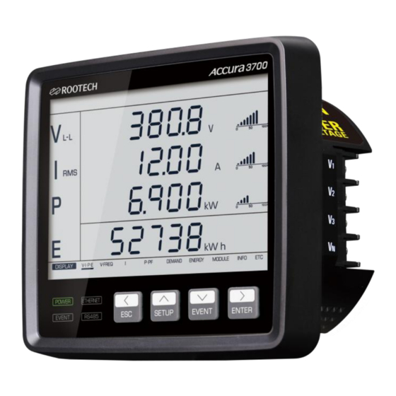
Before installing the Accura 3700, observe the instructions and safety precautions presented in this guide. Caution Power up after voltage and current wiring is completed. Meter Overview Fig 2.1 Accura 3700 Front Fig 2.2 Accura 3700 Side ⓒ 2013 Rootech Inc. All Rights Reserved Page 21... -
Page 22: Fig 2.3 Accura 3700 Rear
Chapter 2 Installation Accura 3700 User Guide Fig 2.3 Accura 3700 Rear Page 22 ⓒ 2013 Rootech Inc. All Rights Reserved... -
Page 23: Fig 2.4 Accura 3700 Dio Module
Fig 2.4 Accura 3700 DIO Module Fig 2.5 Accura 3700 DI Module Fig 2.6 Accura 3700 DO Module Fig 2.7 Accura 3700 AI Module Fig 2.8 Accura 3700 AO Module Fig 2.9 Accura 3700 A4D2 Module ⓒ 2013 Rootech Inc. All Rights Reserved Page 23... -
Page 24: Fig 2.10 Accura 3700 A2D4 Module
Chapter 2 Installation Accura 3700 User Guide Fig 2.10 Accura 3700 A2D4 Module Fig 2.11 Accura 3700 RTD Module Fig 2.12 Accura 3700 ELD Module Fig 2.13 Accura 3700 DC Module Page 24 ⓒ 2013 Rootech Inc. All Rights Reserved... -
Page 25: Components
Chapter 2 Installation Components Fig 2.14 Accura 3700 Components Accura 3700 Two fixing nuts, bolts Rear protection cover Short bar Connector Fig 2.15 I/O Module Components Module protection I/O module cover ⓒ 2013 Rootech Inc. All Rights Reserved Page 25... -
Page 26: Dimension
Chapter 2 Installation Accura 3700 User Guide Dimension Fig 2.16 Accura 3700 Front Dimension Fig 2.17 Accura 3700 Rear Dimension Fig 2.18 Accura 3700 Side Dimension Fig 2.19 Accura 3700 I/O Module Page 26 ⓒ 2013 Rootech Inc. All Rights Reserved... - Page 27 Accura 3700 User Guide Chapter 2 Installation Dimension Device Model Dimension[mm] Power Quality Meter Accura 3700 127W x 114H x 78D I/O module DIO etc. 86.2W x 91H x 27D ⓒ 2013 Rootech Inc. All Rights Reserved Page 27...
-
Page 28: Step 1: Panel Mounting
Fig 2.20 Accura 3700 Mounting[ANSI 4”] Fig 2.21 Accura 3700 Mounting[DIN96] Page 28 ⓒ 2013 Rootech Inc. All Rights Reserved... -
Page 29: Step 2: Voltage/Current Wiring
External PTs should be used in case of measuring the greater voltage than the voltage input specification which is written above. PTs should conform IEC61010-1, Pollution Degree 2, Overvoltage Category Ⅲ. Warning In case of using the external PT, fuse should be installed at PT secondary. ⓒ 2013 Rootech Inc. All Rights Reserved Page 29... - Page 30 UL61010 and IEC61010, Pollution Degree 2, Overvoltage Category Ⅲ Burden > 3VA Note In case that peak expected load is remarkably lower than CT rating current, selecting the much lower CT rating current can improve accuracy and resolution. Page 30 ⓒ 2013 Rootech Inc. All Rights Reserved...
-
Page 31: Fig 2.23 3 Phase 4 Wire 3Pt, 3Ct Wiring, Wiring Mode[Conn] = 3P4U
- In case of wiring without CT, wiring must be done following the guidelines of the company. Fig 2.23 3 Phase 4 Wire 3PT, 3CT Wiring, Wiring Mode[CONN] = 3P4U Note Select 3P4U in “Connection” menu screen. ⓒ 2013 Rootech Inc. All Rights Reserved Page 31... -
Page 32: Fig 2.24 3 Phase 3 Wire 2Pt 3Ct Wiring, Wiring Mode[Conn] = 3P3U
Fig 2.24 3 Phase 3 Wire 2PT 3CT Wiring, Wiring Mode[CONN] = 3P3U Note Select 3P3U in “Connection” menu screen. Fig 2.25 3 Phase 3 Wire 2PT, 2CT wiring, Wiring Mode[CONN] = 3P3U Note Select 3P3U in “Connection” menu screen. Page 32 ⓒ 2013 Rootech Inc. All Rights Reserved... -
Page 33: Fig 2.26 1 Phase 3 Wire 2Pt 2Ct Wiring, Wiring Mode[Conn] = 1P3U
Select 1P3U in “Connection” menu screen. Fig 2.27 1 Phase 2 Wire 1PT 1CT Wiring, Wiring Mode[CONN] = 1P2U Note and V terminals must be used. Select 1P2U in “Connection” menu screen. ⓒ 2013 Rootech Inc. All Rights Reserved Page 33... -
Page 34: Fig 2.28 3 Phase 4 Wire Direct 3Ct Wiring, Wiring Mode[Conn] =3P4U
Fig 2.28 3 Phase 4 Wire Direct 3CT Wiring, Wiring Mode[CONN] =3P4U Note Select 3P4U in “Connection” menu screen. Fig 2.29 3 Phase 3 Wire Voltage Direct 3CT Wiring, Wiring Mode[CONN]=3P3U Note Select 3P3U in “Connection” menu screen. Page 34 ⓒ 2013 Rootech Inc. All Rights Reserved... -
Page 35: Fig 2.30 3 Phase 3 Wire Voltage Direct 2Ct Wiring, Wiring Mode[Conn]=3P3U
Fig 2.30 3 Phase 3 Wire Voltage Direct 2CT Wiring, Wiring Mode[CONN]=3P3U Note Select 3P3U in “Connection” menu screen. Fig 2.31 1 Phase 3 Wire Voltage Direct 2CT Wiring, Wiring Mode[CONN]=1P3U Note Select 1P3U in “Connection” menu screen. ⓒ 2013 Rootech Inc. All Rights Reserved Page 35... -
Page 36: Fig 2.32 1 Phase 3 Wire Voltage Direct 1Ct Wiring, Wiring Mode[Conn]=1P2U
Chapter 2 Installation Accura 3700 User Guide Fig 2.32 1 Phase 3 Wire Voltage Direct 1CT Wiring, Wiring Mode[CONN]=1P2U Note and V terminals must be used. Select 1P2U in “Connection” menu screen. Page 36 ⓒ 2013 Rootech Inc. All Rights Reserved... -
Page 37: Step 3: Accura 3700 External Communication
Ethernet switching supporting RSTP and adjusting the order of priority as the corresponding switch is configured as the route. Fig 2.33 Accura 3700 Ethernet Communication Port ⓒ 2013 Rootech Inc. All Rights Reserved Page 37... -
Page 38: Fig 2.34 Accura 3700 Ehternet Connection
STP[Shielded Twisted Pair] or SFTP[Screened Foiled Twisted Pair] cable is recommended. Refer to the “IP/Subnet mask/Gateway” menu screen. Note Recommend using the Ethernet switch supporting the RSTP[Rapid Spanning Tree] protocol for quick recovery in case of ring connection. Page 38 ⓒ 2013 Rootech Inc. All Rights Reserved... -
Page 39: Rs-485 Communication
Screw Terminal[Pluggable] Protocol Modbus RTU Wire 0.21 to 3.5 mm [24 to 12 AWG], Shielded twisted pair Maximum Cable Length 1219m[4000ft] Maximum Connection Device 32/bus Connect Shield line to G terminal. ⓒ 2013 Rootech Inc. All Rights Reserved Page 39... -
Page 40: Step 4: Accura 3700 Power Supply/Ground
Item Description Connector Name Connector Type Screw Terminal[Pluggable] Wiring 2.1 to 3.5 mm [14 to 12 AWG] Compliance Note Wire the meter’s ground terminal to the earth ground of distribution panel. Page 40 ⓒ 2013 Rootech Inc. All Rights Reserved... -
Page 41: Step 5: Accura 3700 Extension Module Addition
To add extension modules at the rear of Accura 3700, remove the rubber cover which is for rear connector protection. Fig 2.38 I/O Module Addition Note I/O modules can be added up to three regardless of order and type. But AO module can be added up to two. ⓒ 2013 Rootech Inc. All Rights Reserved Page 41... -
Page 42: Step 6: I/O Module
Connector Type Screw type terminal [Pluggable] Application Dry contact Wiring Compliance 0.21 to 3.5 mm [24 to 12 AWG] Rating DC 5V[Self excitation] Insulation AC 2,000V 1 minute Minimum Pulse Width 10msec Page 42 ⓒ 2013 Rootech Inc. All Rights Reserved... - Page 43 Output Type Command Latch “on” outputs “off” outputs Periodic pulse Periodic pulse outputs Periodic pulse stops Single pulse[uncountable] Single pulse outputs. Additional generations of “on” command within pulse period are ignored. ⓒ 2013 Rootech Inc. All Rights Reserved Page 43...
-
Page 44: Fig 2.41 Dc Relay Application
For type selection of Latch or pulse, refer to “Output Channel type” menu screen of DO module configuration. Fig 2.41 DC Relay Application Fig 2.42 AC Relay Application Note Recommend to use Clamp Diode or Varistor not to exceed the rating voltage at digital output during switching. Page 44 ⓒ 2013 Rootech Inc. All Rights Reserved... -
Page 45: Di Module
Screw Type TerminalPluggable] Application Dry contact Wiring Compliance 0.21 to 3.5 mm [24 to 12 AWG] Rating DC 5V[Self excitation] Insulation Maximum AC 2,000V for 1 minute 10msec Minimum Pulse Width ⓒ 2013 Rootech Inc. All Rights Reserved Page 45... - Page 46 Chapter 2 Installation Accura 3700 User Guide Fig 2.44 Digital Input (Dual Input Structure) Warning Applying external voltage to digital input channel causes damage to meter because of internally DC 5V. Page 46 ⓒ 2013 Rootech Inc. All Rights Reserved...
-
Page 47: Do Module
Command Latch “on” outputs “off” outputs Periodic pulse Periodic pulse outputs Periodic pulse stops Single Single pulse outputs. Additional generations of “on” command pulse[uncountable] within pulse period are ignored. Not available ⓒ 2013 Rootech Inc. All Rights Reserved Page 47... -
Page 48: Fig 2.46 Dc Relay Application
Fig 2.46 DC Relay Application Fig 2.47 AC Relay Application Note Recommend to use Clamp Diode or Varistor not to power up to exceeding the voltage rating to digital output during switching. Page 48 ⓒ 2013 Rootech Inc. All Rights Reserved... -
Page 49: Ai Module
0.21 to 3.5 mm [24 to 12 AWG] Compliance Current Input DC 0 ~ 20mA ±0.5% Full Scale Accuracy Fig 2.49 Analog Input Warning Applying current exceeding 20mA can damage the internal circuit. ⓒ 2013 Rootech Inc. All Rights Reserved Page 49... -
Page 50: Ao Module
Below 450Ω ±0.5% Full Scale Accuracy Fig 2.51 AO Module Analog Output Warning In case of voltage dip over 10V on 0 ~ 20mA current output, constant current output is not guaranteed. Page 50 ⓒ 2013 Rootech Inc. All Rights Reserved... -
Page 51: A4D2/A2D4 Module
Item Description Connector Type Screw Type Terminal[Pluggable] Wiring 0.21 to 3.5 mm [24 to 12 AWG] Compliance Current Output DC 0 ~ 20mA Load resistance Below 450Ω ±0.5% Full Scale Accuracy ⓒ 2013 Rootech Inc. All Rights Reserved Page 51... -
Page 52: Fig 2.54 A4D2/A2D4 Module Analog Output
Latch, Pulse, Periodic Pulse , Energy Pulse Minimum Pulse Period 20msec Minimum Pulse Width 10msec Insulation AC 2,000V 1 minute AC/DC 400V 350mA[max. 1A] Maximum Rating Action of digital output is as followed. Page 52 ⓒ 2013 Rootech Inc. All Rights Reserved... -
Page 53: Fig 2.55 Dc Relay Application
Peak AC / DC Value, max 1A current is energizing cycle 100ms one-shot current. Note For type selection of Latch or pulse, refer to “Output Channel type” menu screen of DO module configuration. Fig 2.55 DC Relay Application ⓒ 2013 Rootech Inc. All Rights Reserved Page 53... -
Page 54: Fig 2.56 Ac Relay Application
Accura 3700 User Guide Fig 2.56 AC Relay Application Note Recommend to use Clamp Diode or Varistor not to power up to exceeding the voltage rating to digital output during switching. Page 54 ⓒ 2013 Rootech Inc. All Rights Reserved... -
Page 55: Rtd Module
Item Description Connector Type Screw Type Terminal[Pluggable] Wiring 0.21 to 3.5 mm [24 to 12 AWG] Compliance RTD Sensor PT100, PT1000 Wiring Mode 2, 3, 4 wires ±0.5% Full Scale Accuracy ⓒ 2013 Rootech Inc. All Rights Reserved Page 55... - Page 56 Chapter 2 Installation Accura 3700 User Guide Fig 2.58 RTD Input [4Wires] [3Wires] [2Wires] Page 56 ⓒ 2013 Rootech Inc. All Rights Reserved...
-
Page 57: Eld Module
Connector Type Screw Type Terminal[Pluggable] Wiring Compliance 0.21 to 3.5 mm [24 to 12 AWG] Leakage Current Input Voltage-type ZCT 200mA/100mV @ 1.2kΩ Burden ±0.5% Full Scale Accuracy Fig 2.60 ELD Input ⓒ 2013 Rootech Inc. All Rights Reserved Page 57... - Page 58 Peak AC / DC Value, max 1A current is energizing cycle 100ms one-shot current. Note For type selection of Latch or pulse, refer to “Output Channel type” menu screen of DO module configuration. Page 58 ⓒ 2013 Rootech Inc. All Rights Reserved...
-
Page 59: Fig 2.61 Dc Relay Application
Fig 2.61 DC Relay Application Fig 2.62 AC Relay Application Note Recommend to use Clamp Diode or Varistor not to power up to exceeding the voltage rating to digital output during switching. ⓒ 2013 Rootech Inc. All Rights Reserved Page 59... -
Page 60: Dc Module
Screw Type Terminal[Pluggable] Shunt [Rectifier Output Current] 50, 60, 100mV Shunt [Battery Current] ± 50, 50, 60, 100mV Wiring Compliance 0.21 to 3.5 mm [24 to 12 AWG] Fig 2.64 DC Voltage/Current Page 60 ⓒ 2013 Rootech Inc. All Rights Reserved... - Page 61 AC 2,000V 1 minute Minimum Pulse Width 10msec Fig 2.65 Digital Input(Dual Input Structure) Warning Applying external voltage to digital input channel causes damage to meter because of internally DC 5V. ⓒ 2013 Rootech Inc. All Rights Reserved Page 61...
- Page 62 Peak AC / DC Value, max 1A current is energizing cycle 100ms one-shot current Note For type selection of Latch or pulse, refer to “Output Channel type” menu screen of DO module configuration. Page 62 ⓒ 2013 Rootech Inc. All Rights Reserved...
-
Page 63: Fig 2.66 Dc Relay Application
Fig 2.66 DC Relay Application Fig 2.67 AC Relay application Note Recommend to use Clamp Diode or Varistor not to power up to exceeding the voltage rating to digital output during switching. ⓒ 2013 Rootech Inc. All Rights Reserved Page 63... -
Page 64: Chapter 3 Operation/Setup
Left[<], Up[^], Down[v], and Right[>] buttons. At this time, as display menu is displayed on navigation menu space at lower part of LCD, the position where the presently displayed page is can be easily confirmed. Page 64 ⓒ 2013 Rootech Inc. All Rights Reserved... -
Page 65: Fig 3.2 Display Mode Screen Example
EVENT button. In the event mode, event segment of upper bar is lighted on. ⓒ 2013 Rootech Inc. All Rights Reserved Page 65... -
Page 66: Fig 3.4 Event Mode Screen Example
In setup mode, navigation menu on the lower part of LCD changes from the display mode to setup mode. If the event generates, RED backlight duration time is default 10 seconds and can be additionally configured up to 999 minutes by the user configuration. Page 66 ⓒ 2013 Rootech Inc. All Rights Reserved... - Page 67 Automatically return to display mode if there is no button operation for 10 minutes at the setup mode. Automatically return to setup mode if there is no button operation for 1 minute modifying the configured value ⓒ 2013 Rootech Inc. All Rights Reserved Page 67...
-
Page 68: Display Mode
Blinks in case that the event generates Sum of Three Phase EVENT Blinks in case of Ethernet communication ETHERNET Blinks in case of RS-485 Communication RS-485 d decimal.tens digit is displayed only up to one. Page 68 ⓒ 2013 Rootech Inc. All Rights Reserved... - Page 69 Meter information such as serial number, version, etc. INFO Not presently used Start-up Time Accura 3700 needs 30 seconds for start-up time. During the time, nothing is displayed on LCD screen. ⓒ 2013 Rootech Inc. All Rights Reserved Page 69...
-
Page 70: Display Screen
Chapter 3 Operation/Setup Accura 3700 User Guide Display Screen Accura 3700 totally displays state information of measurement parameter and selected extension module. Page 70 ⓒ 2013 Rootech Inc. All Rights Reserved... -
Page 71: Measurement Parameter Display Screen
THD, and frequency are displayed in order. By touching Up[v] button, values are displayed in the reverse order. ⓒ 2013 Rootech Inc. All Rights Reserved Page 71... -
Page 72: Fig 3.8 Line To Line Voltage Specific Measurement Value Display Screen
By touching Up[v] button, values are displayed in the reverse order. Page 72 ⓒ 2013 Rootech Inc. All Rights Reserved... -
Page 73: Fig 3.10 Power Specific Measurement Value Display Screen
Up[v] button, values are displayed in the reverse order. Net energy is the value which subtracts delivered energy from received energy, and sum of energy is the value which adds received energy and delivered energy. ⓒ 2013 Rootech Inc. All Rights Reserved Page 73... -
Page 74: Fig 3.12 Net Energy Display Screen In Energy Display Screen
State Explanation Root port Route toward RSTP Root Node Designated port Route toward RSTP Leaf Node Backup port Alternative Route toward Same LAN Alternative port Alternative Route toward RSTP Root Node Page 74 ⓒ 2013 Rootech Inc. All Rights Reserved... -
Page 75: Fig 3.14 Temperature Display Screen In Etc Display Screen
At ETC screen, measured temperature by the temperature sensor positioned at the rear cover of Accura 3700 and present time can be confirmed. Fig 3.14 Temperature Display Screen in ETC Display Screen ⓒ 2013 Rootech Inc. All Rights Reserved Page 75... -
Page 76: Extension Module State View
Channel information is displayed corresponding to the feature of each I/O and at the upper part of LCD, the ID of corresponding module is displayed. In case of one extension module added, by Page 76 ⓒ 2013 Rootech Inc. All Rights Reserved... -
Page 77: Fig 3.17 Display Screen Of The Second Extension Module In Module Screen
Extension modules that can be added at the rear of Accura 3700 is up to three modules. Even though the same type module addition is supported, AO modules can be added up to two. Display screens for each type of extension modules are followed. ⓒ 2013 Rootech Inc. All Rights Reserved Page 77... -
Page 78: Display Screen For Classification Of Extension Modules
Chapter 3 Operation/Setup Accura 3700 User Guide Display Screen for Classification of Extension Modules Display the state information of Accura 3700 extension modules for each type. Page 78 ⓒ 2013 Rootech Inc. All Rights Reserved... -
Page 79: Fig 3.18 Dio Module First Screen
The state of DO contact point corresponding to DO display state is as followed corresponding to the configured value of contact point input polarity. Polarity normal setup corresponds to the contact point A and polarity reverse setup corresponds to the contact point B. ⓒ 2013 Rootech Inc. All Rights Reserved Page 79... -
Page 80: Fig 3.19 Di Module First Screen
DO channel of DIO modules. As the state of 4 channels is displayed on one screen, the state of 6 channels is displayed on two screens. Each screen can be confirmed in order by using Up[^], Down[v] button. Fig 3.20 DO Module First Screen Page 80 ⓒ 2013 Rootech Inc. All Rights Reserved... -
Page 81: Fig 3.21 Ai Module First Screen
12mA is displayed at the third row and 100 is displayed at the fourth row. The output signal range and the conversion ratio with converted measurement data of mA is configured at Setup mode and different setup is available for each channel. ⓒ 2013 Rootech Inc. All Rights Reserved Page 81... -
Page 82: Fig 3.22 Ao Module First Screen
Each screen can be confirmed in order by using Up[^], Down[v] button. Analog output channel has the same function as AO module channel and digital output channel has the same function as DO module channel. Page 82 ⓒ 2013 Rootech Inc. All Rights Reserved... -
Page 83: Fig 3.24 A2D4 Module First Screen
The state of 1 digital output channels is displayed on one screen. Each screen can be confirmed in order by using Up[^], Down[v] button. Digital output channel has the same function as DO module channel. ⓒ 2013 Rootech Inc. All Rights Reserved Page 83... -
Page 84: Fig 3.26 Eld Module First Screen
Up[^], and Down[v] button. Digital input channel has the same function as DI module channel and digital output channel has the same function as DO module channel. Fig 3.27 DC Module First Screen Page 84 ⓒ 2013 Rootech Inc. All Rights Reserved... -
Page 85: Event Mode
When the event alarm generates, event alarm is automatically cleared by long touching the event button. Entering the event mode, event segment of upper bar turns on and displays event logs up to 500. ⓒ 2013 Rootech Inc. All Rights Reserved Page 85... - Page 86 “[Beep]” sounds when touching. Touch more than one second. After one second, “[Beep]” sounds. Note Automatically return to display mode if there is no button operation for 10 minutes at the event mode. Page 86 ⓒ 2013 Rootech Inc. All Rights Reserved...
-
Page 87: Fig 3.30 Event Log Number Example
E998 E999 Final Event Log number E999 Final Event Log number Event log number is as followed. Event Log number N-499 Oldest saved event Event Log number N Latest saved event ⓒ 2013 Rootech Inc. All Rights Reserved Page 87... - Page 88 000 ~ 999 SUL.S[Swell Swell start event generates[Phase B Start] [d][d][d][d] v Voltage when swell start event generates Event generated phase [A, B, C, AB, BC, CA] is displayed. d decimal. Page 88 ⓒ 2013 Rootech Inc. All Rights Reserved...
- Page 89 Display the information when fuse fail end event generates Display Event number - E[Event] [d][d][d] 000 ~ 999 - B FuSE[Fuse] Fuse fail end event generates[Phase B End[End] Event generated phase [A, B, C] is displayed. d decimal. ⓒ 2013 Rootech Inc. All Rights Reserved Page 89...
- Page 90 000 ~ 999 DI Close event generates dI.cL[DI Close], Corresponding module name such dI[DI] as DIO, DI. DC etc. 1 ~ 12 [Display the event Ch.[d][d] generated channel] d decimal. Page 90 ⓒ 2013 Rootech Inc. All Rights Reserved...
- Page 91 000 ~ 999 [d][d][d] AI Over event generates aI.ou[AI Over], Corresponding module name such as AI, DC, AI[AI] RTD, ELD etc. 1 ~ 6[Display the event generated channel] Ch.[d] d decimal. ⓒ 2013 Rootech Inc. All Rights Reserved Page 91...
- Page 92 1 ~ 3[Display the event generated Ch.[d] channel] d decimal. No Event Logs Display as followed in case that there is no saved event log. Display No event logs No[no] Evnt[Event] Page 92 ⓒ 2013 Rootech Inc. All Rights Reserved...
-
Page 93: Setup Mode
Up[^], Down[v], Right[>], ESC, and ENTER button. At this time, the position of the presently displayed page can be easily confirmed as setup menu is displayed on navigation menu space at lower part of LCD. ⓒ 2013 Rootech Inc. All Rights Reserved Page 93... -
Page 94: Setup Menu
Chapter 3 Operation/Setup Accura 3700 User Guide Setup Menu Page 94 ⓒ 2013 Rootech Inc. All Rights Reserved... -
Page 95: Meter Setup
CT Rating [Ct Setting Range - Pr[Primary] CT Primary Rating [d][d][d][d][d].[d] 00000.1 ~ 99999.9 [default 50.0] CT Secondary Rating - Sc[Secondary] [d][d].[d] 00.1 ~ 99.9 [default 50.0] d decimal. ⓒ 2013 Rootech Inc. All Rights Reserved Page 95... - Page 96 Reference current is used as the reference value of TDD configuration. Also it is used as the reference of front bar graph display. Demand Sub Interval [dMd Demand, SbIt Sub Interval] Setting Range 1 ~ 60 minute[default 15] Page 96 ⓒ 2013 Rootech Inc. All Rights Reserved...
-
Page 97: Fig 3.31 Demand Measuring Method
Fig 3.31 Demand Measuring Method Reactive Power Calculation Method for Each Phase [qMd Q Method] Setting Range - Md1[Method 1, default] General calculation method Harmonic calculation method - Md2[Method 2] ⓒ 2013 Rootech Inc. All Rights Reserved Page 97... -
Page 98: Fig 3.32 Power Sign[General Calculation]
S S S arms arms brms brms crms crms Page 98 ⓒ 2013 Rootech Inc. All Rights Reserved... - Page 99 3 phase sum power] Method 1: [Vector Sum] PF Method 2: [Arithmetic Sum] PF ⓒ 2013 Rootech Inc. All Rights Reserved Page 99...
-
Page 100: Fig 3.33 Difference Between Two Methods That Calculate Each Phase Sum Power
Unit is mA and external CT secondary input at Accura 3700 is the reference. In case of configuring as 20mA, the default value, if the CT of which secondary rating is 5A, the value under the 1/250 of the rating would be displayed as 0. Page 100 ⓒ 2013 Rootech Inc. All Rights Reserved... - Page 101 Reactive Power Sign Display ON/OFF [Uar Var, SIgn Sign ] Setting Range Display sign corresponding to the current on[ON, default] phase Do not display the sign to reactive power oFF[OFF] ⓒ 2013 Rootech Inc. All Rights Reserved Page 101...
- Page 102 1. So, as Var Sign is configured as ON at this configuration item, the sign is given to reactive power. To always process the reactive power as positive number regardless of the reactive power calculation method, configuration of the Var Sign should be OFF. Page 102 ⓒ 2013 Rootech Inc. All Rights Reserved...
-
Page 103: Event Setup
[3P3U], dip start voltage is configured as a percentage for line to line voltage, which is the reference voltage and in other cases[3P4U, 1P3U, 1P2U], dip start voltage is configured as a percentage for the value that the reference voltage is converted to line to neutral voltage. ⓒ 2013 Rootech Inc. All Rights Reserved Page 103... - Page 104 Ratio to reference voltage 1.0 ~ 98.0% [default 90.0%] Dip End Voltage Display [3P4U, 1P3U, 1P2U] [d][d][d].[d] V/kV Converting the reference voltage[Line to line voltage] to line to neutral voltage x percentage Page 104 ⓒ 2013 Rootech Inc. All Rights Reserved...
-
Page 105: Fig 3.34 Dip Event Setup[3P3U]
Example of the case that the voltage reference of METER setup menu is configured as 380V. Fig 3.35 Dip Event Setup[3P4U] Example of the case that the voltage reference of METER setup menu is configured as 380V. ⓒ 2013 Rootech Inc. All Rights Reserved Page 105... - Page 106 Setting Range Ratio to reference voltage 101.0 ~ 998.0% [default 108.0%] Swell End Voltage Display Converting the reference voltage[Line [d][d][d].[d] V/kV to line voltage] to line to neutral voltage x percentage Page 106 ⓒ 2013 Rootech Inc. All Rights Reserved...
-
Page 107: Fig 3.36 Swell Event Setup[3P3U]
Example of the case that the voltage reference of METER setup menu is configured as 380V. Fig 3.37 Swell Event Setup[3P4U] Example of the case that the voltage reference of METER setup menu is configured as 380V. ⓒ 2013 Rootech Inc. All Rights Reserved Page 107... - Page 108 Black Out Event[bLAk Out Black Out ] Setting Range Black out event on Black out event off oFF[default] Case that all voltage and current are measured as 0 is decided as black out. Page 108 ⓒ 2013 Rootech Inc. All Rights Reserved...
-
Page 109: Rs-485 Communication Setup
57600 115200 bps 11520 Parity Bit [Prty Parity Bit ] Setting Range Even Parity EuEn[default] None Parity nonE Odd Parity Stop Bit [StoP Stop Bit ] Setting Range 1[default] ⓒ 2013 Rootech Inc. All Rights Reserved Page 109... -
Page 110: Ethernet Communication Setup
If the communication map is configured as r200, communication is available on the same map of Rootech product RTM200. ETHERNET Communication Setup IP[IP IP ] Setting Range 000.000.000.000 ~ 255.255.255.255 [default 010.010.010.100] Page 110 ⓒ 2013 Rootech Inc. All Rights Reserved... - Page 111 255.255.000.000 ~ 255.255.255.252 [default 255.255.255.000] Gateway[gatE Gateway ] Setting Range 000.000.000.000 ~ 255.255.255.255 [default 010.010.010.001] Mac Address [Mac Mac Address ] Mac Address Display [h][h].[h][h] [h][h].[h][h] [h][h].[h][h] h hexadecimal.[16] ⓒ 2013 Rootech Inc. All Rights Reserved Page 111...
- Page 112 Setting Range 000.000.000.000 255.255.255.255 [default 010.010.010.001] Modbus-TCP Timeout[tcp tInE Out TCP Time Out ] Setting Range Timeout time configuration for non-asking 5 ~ 600 second [default 600 sec] the Modbus-TCP communication Page 112 ⓒ 2013 Rootech Inc. All Rights Reserved...
-
Page 113: Reset Setup
Maximum/Minimum Reset[Max Maximum, MinMinimum] Reset Setting Range Maximum/minimum reset rESEt[Reset] Demand maximum is reset by the maximum/minimum reset. Energy Reset [Enrg Energy ] Setting Range Energy[kWh, kVARh, kVAh] reset rESEt[Reset] ⓒ 2013 Rootech Inc. All Rights Reserved Page 113... - Page 114 Chapter 3 Operation/Setup Accura 3700 User Guide All Reset [ALL ALL ] Setting Range [Demand, maximum/minimum, rESEt[Reset] energy] reset Page 114 ⓒ 2013 Rootech Inc. All Rights Reserved...
-
Page 115: Display Setup
Brightness changes to the ‘LCD brightness’ low configuration after the configured time pass after the last button touching to save power consumption. LCD Event RED Back Light Time [Eunt Event, b.Lgt Back Light ] Setting Range 0 ~ 999 min[default 0] ⓒ 2013 Rootech Inc. All Rights Reserved Page 115... - Page 116 CT ratio by 0.2A [Provides 2A when default CT rating ratio 10, the phase keeps the feature that lags for 60 degrees for the voltage. Page 116 ⓒ 2013 Rootech Inc. All Rights Reserved...
- Page 117 Swell event once Swell Cycle: 5cycles Swell Size: 130% of reference voltage Voltage change after Demo starts: Vref 15 cycles are kept → Swell 5 cycles generate → Kept after returning to Vref ⓒ 2013 Rootech Inc. All Rights Reserved Page 117...
-
Page 118: Extension Module Id Setup [Module]
State change alarm is provided through communication Page 118 ⓒ 2013 Rootech Inc. All Rights Reserved... - Page 119 “Save” and executing configuration saving by long touching the ENTER button, it is modified into “Saved” and notifies that it is saved as the latest state. Module Setup Information Save Case that modification is detected Save Saved Case that configuration is saved ⓒ 2013 Rootech Inc. All Rights Reserved Page 119...
-
Page 120: Individual Extension Module Setup
ELD module Leakage current input 6 channels, digital output 1 channel DC module DC voltage input 1 channel, DC current input 2 channels Digital input 4 channels, Digital output 1 channel Page 120 ⓒ 2013 Rootech Inc. All Rights Reserved... -
Page 121: Module Setup Screen
Accura 3700 User Guide Chapter 3 Operation/Setup Module Setup Screen ⓒ 2013 Rootech Inc. All Rights Reserved Page 121... -
Page 122: Di Module Setup [DiDi]
10 ~ 255msec [default 10msec] only if the input state is kept over the configured time. It is configuration item for not to react at chattering and noise signal. d decimal. Page 122 ⓒ 2013 Rootech Inc. All Rights Reserved... -
Page 123: Do Module Setup [DoDo]
Open in the case of ON order rEu[Reverse] d decimal. The state of DO contact point corresponding to the DO display is as the following chart corresponding to configured polarity value. ⓒ 2013 Rootech Inc. All Rights Reserved Page 123... - Page 124 Pulse Period [do_1 DO Channel 1, P.Prd Pulse Period] This menu item is displayed only when all pulse type is selected at the “Output Channel Type” setup menu. Page 124 ⓒ 2013 Rootech Inc. All Rights Reserved...
- Page 125 Parameter[do_1 DO Channel 1, Para Parameter] This menu item is displayed only when Latch, Periodic pulse or Uncountable single pulse type is selected at the “Output Channel Type” setup menu. ⓒ 2013 Rootech Inc. All Rights Reserved Page 125...
- Page 126 This menu item is displayed when countable single pulse type[PuLS.C] is selected at the “Output Channel Type” setup menu and other items are selected except for no. at the “Pulse Connected Ooutput” setup menu. Configure the energy that corresponds for single pulse output. Page 126 ⓒ 2013 Rootech Inc. All Rights Reserved...
- Page 127 DO Module Software Version[SUEr Software version, b bootload, F Firmware] Screen to confirm the bootload and firmware version of added DO modules. Display Bootload version Firmware version [d].[d][d] d decimal. ⓒ 2013 Rootech Inc. All Rights Reserved Page 127...
-
Page 128: Dio Module Setup [DioDio]
[d] channel 1 ~ 6 AI_[d] AI module has 6 AI channels. Setting Range Input range 0 ~ 20mA type 0-20[default] Input range 4 ~ 20mA type 4-20 d decimal. Page 128 ⓒ 2013 Rootech Inc. All Rights Reserved... - Page 129 Configure the primary value of external transduce that corresponds to analog input 20mA. For example if temperature transduce that is converted into 20mA is connected when the external temperature is 200°C, then configure 200.0 at this item. ⓒ 2013 Rootech Inc. All Rights Reserved Page 129...
- Page 130 A/D sampling period for measuring analog input is 1msec. The data measured per 1msec can be used as it is, but for obtaining more accurate data using the average for certain interval, configure the Moving Average high. Page 130 ⓒ 2013 Rootech Inc. All Rights Reserved...
- Page 131 ‘Over threshold value and under ‘Under threshold value Over threshold value is the value of generating alarm. Under threshold value is lower threshold value as much as hysteresis from Over threshold value. ⓒ 2013 Rootech Inc. All Rights Reserved Page 131...
- Page 132 AI Channel Alarm Hysteresis Value Setup [AI_I AI Channel 1, hySt Hysteresis Value] Displayed only when the event configuration of AI channel is not ‘oFF’, and configure the hysteresis value. Setting Range 1 ~ 9999 [d][d][d][d] [default 1] Hysteresis value d decimal. Page 132 ⓒ 2013 Rootech Inc. All Rights Reserved...
-
Page 133: Ao Module Setup [Ao Ao]
Phase CA line to line voltage U_ca[Vca] Average line to line voltage U_LL[V Phase A Current A_a[Ia] Phase B Current A_b[Ib] Phase C Current A_c[Ic] Average Current A[I] ㅏ Active power[kW] W[kW] Power Factor(PF) ⓒ 2013 Rootech Inc. All Rights Reserved Page 133... - Page 134 In case that the output range is configured as 4 ~ 20mA, output current is provided by calculating the converted value as the following equation if converted value 1(high value, u1) for output Page 134 ⓒ 2013 Rootech Inc. All Rights Reserved...
- Page 135 S Select sign ‘0’[positive] ‘-‘[negative] by using Up[^], Down[v] button. Analog Output Minimum [Ao_I AO channel 1, Lo Low] Setting Range -999999 ~ 999999 [s][d][d][d][d][d][d] [default d decimal. S Select sign ‘0’[positive] ‘-‘[negative] by using Up[^], Down[v] button. ⓒ 2013 Rootech Inc. All Rights Reserved Page 135...
-
Page 136: A4D2 Module Setup [Module] [A4D2 A4D2]
DO channels as it is the same with AO and DO modules. A4D2 Channel Configuration [d] Channel 1 ~ 4 Ao_[d] [d] Channel 1 ~ 2 do_[d] A4D2 module has 4 AO channels and 2 Do channels. d decimal. Page 136 ⓒ 2013 Rootech Inc. All Rights Reserved... -
Page 137: A2D4 Module Setup [A2D4A2D4]
Refer the configuring method of AO and DO modules for the configuration of AO and DO channels. A2D4 Channel Configuration [d] Channel 1 ~ 2 Ao_[d] [d] Channel 1 ~ 4 Do_[d] A2D4 module has 2 AO Channels and 4 Do Channels. d decimal. ⓒ 2013 Rootech Inc. All Rights Reserved Page 137... -
Page 138: Rtd Module Setup [RtdRtd]
Event generates if the RTD is not connected or connecting wire is disconnected in the state that RTD sensor is connected. It is commonly applied for channel 1, 2 and 3. Setting Range oFF[OFF default], on[ON] Whether there is event for not connecting the RTD or disconnection. Page 138 ⓒ 2013 Rootech Inc. All Rights Reserved... - Page 139 ‘Over threshold value and under ‘Under threshold value Over threshold value is the value of generating alarm. Under threshold value is lower threshold value as much as hysteresis from Over threshold value. ⓒ 2013 Rootech Inc. All Rights Reserved Page 139...
- Page 140 RTD Channel Alarm Hysteresis Value Setup [Ch_I Channel 1, hySt Hysteresis Value] Only generated when the event configuration of RTD Channel is not ‘oFF’, and configure hysteresis value. Setting Range 5 ~ 999d] [d][d][d] [default 5nge d decimal. Page 140 ⓒ 2013 Rootech Inc. All Rights Reserved...
-
Page 141: Eld Module Setup [EldEld]
RMS measurement. Configure leakage current One[One Cycle] measurement period as one cycle. RMS measurement. Configure leakage current Fund[Fundamental] measurement period as one cycle. Fundamental measurement. d decimal. ⓒ 2013 Rootech Inc. All Rights Reserved Page 141... - Page 142 ‘Over threshold value and under ‘Under threshold value Over threshold value is the value of generating alarm. Under threshold value is lower threshold value as much as hysteresis from Over threshold value. Page 142 ⓒ 2013 Rootech Inc. All Rights Reserved...
- Page 143 Leakage Current Alarm Hysteresis Value[Ch_IChannel 1, hySt Hysteresis Value ] Only generated when event configuration of leakage current is not ‘oFF’, and configure the hysteresis value. Setting Range 0.01 ~ 2.00A [d][d].[d][d] [default 0.04] Hysteresis value d decimal. ⓒ 2013 Rootech Inc. All Rights Reserved Page 143...
- Page 144 ELD Module Software Version [SUEr Software version, b bootload, F Firmware Version] Screen to confirm the bootload and firmware version of added ELD modules. Display Bootload version Firmware version [d].[d][d] d decimal. Page 144 ⓒ 2013 Rootech Inc. All Rights Reserved...
-
Page 145: Dc Module Setup [DcDc]
‘Over threshold value and under ‘Under threshold value Over threshold value is the value of generating alarm. Under threshold value is lower threshold value as much as hysteresis from Over threshold value. ⓒ 2013 Rootech Inc. All Rights Reserved Page 145... - Page 146 Displayed only when the event configuration of rectifier output current is not ‘oFF’, and configure the hysteresis value. Setting Range 1 ~ 20V [d][d] [default 4 V] Hysteresis value d decimal. Page 146 ⓒ 2013 Rootech Inc. All Rights Reserved...
- Page 147 ‘Over threshold value and under ‘Under threshold value Over threshold value is the value of generating alarm. Under threshold value is lower threshold value as much as hysteresis from Over threshold value. ⓒ 2013 Rootech Inc. All Rights Reserved Page 147...
- Page 148 Displayed only when the event configuration of rectifier output current is not ‘oFF’, and configure the threshold value. Setting Range 1 ~ 9999A [d][d][d][d] [default default 100 A] Threshold value d decimal. Page 148 ⓒ 2013 Rootech Inc. All Rights Reserved...
- Page 149 On the other hand, by configuring the sign configuration as ON, if voltage of reverse polarity is input, it is measured as negative number proportionally. ⓒ 2013 Rootech Inc. All Rights Reserved Page 149...
- Page 150 In case that input value often continues to go above and below the event alarm threshold value, adequate hysteresis configuration is needed for effective event management as there can be so many events generated. Page 150 ⓒ 2013 Rootech Inc. All Rights Reserved...
- Page 151 DI module has 4 DI channels. Setting Range If the external contact point is ON, norM[Normal, default] display ON If the external contact point is OFF , rEu[Reverse] display ON d decimal. ⓒ 2013 Rootech Inc. All Rights Reserved Page 151...
- Page 152 Event generates for all changes of DI input both[Both] close and open. Event close open configuration is unrelated to polarity configuration and decided corresponding to the state of contact point. Page 152 ⓒ 2013 Rootech Inc. All Rights Reserved...
- Page 153 DC Module Software Version[SUEr Software version, b bootload, F Firmware ] Screen that confirms the bootload and firmware version of added DC module. Display Bootload version Firmware version [d].[d][d] d decimal. ⓒ 2013 Rootech Inc. All Rights Reserved Page 153...
-
Page 154: Information [InfoInformation]
Hardware Version [H∪Er Hardware Version ] Display Hardware version [d].[d][d] _[d][d] d decimal. Software Version [S∪Er Software Version ] Display Application version a[Application] [d].[d][d] Firmware version F[Firmware] [d].[d][d] d decimal. Page 154 ⓒ 2013 Rootech Inc. All Rights Reserved... -
Page 155: Required Configuration Step
Right[>] button. Move to Sc[Secondary] by continuous touching the Right[>] button. ⑤ Repeat substep ③, ④ until the number selection of all digits is completed. ⑥ Long touch the Enter button all number configuration is completed. ⓒ 2013 Rootech Inc. All Rights Reserved Page 155... - Page 156 Long touch ENTER button only the number that is possible to be configured blinks. ③ Select the number by touching UP [^] or Down[v] button. ④ Move to the next[left or right] digit number to select by touching Left[<], Right[>] button. Page 156 ⓒ 2013 Rootech Inc. All Rights Reserved...
- Page 157 CT primary [Primary], [Secondary] ] current rating is used as a ratio only for measuring the current. Used as the voltage reference for Dip/Swell event setup. Used as value of the bar graph display on the front side. ⓒ 2013 Rootech Inc. All Rights Reserved Page 157...
-
Page 158: Appendix A Specification
3.3W Accura 3700 A4D2 module 2.5W Accura 3700 A2D4 module 1.7W Accura 3700 RTD module 0.6W Accura 3700 ELD module 0.6W Accura 3700 DC module 1.0W General Weight Accura 3700 510g Page 158 ⓒ 2013 Rootech Inc. All Rights Reserved... - Page 159 0 ~ 200V DC current Rectifier output 0 ~ 100mV[Shunt Needed] current Battery current 0 ~ 100mV[Shunt Needed] Peak AC / DC Value, max 1A current is energizing cycle 100ms one-shot current. ⓒ 2013 Rootech Inc. All Rights Reserved Page 159...
-
Page 160: Appendix B Standard Compliance
Rated Power Frequency Magnetic Field IEC61000-4-11 Voltage Dip/Short Interruptions Certification UL61010-1 UL Mark EN61326-1, EN61326-2-1 CE Mark KN22, KN24 KCC Mark Part15 Subpart B FCC Mark ISO 9001:2001[QMS-1347] ISO Certification General Warranty 2 Years Page 160 ⓒ 2013 Rootech Inc. All Rights Reserved... -
Page 161: Appendix C Accuracy/Reliability
± 0.5% Full scale Leak Current Input 0.0 ~ 999.9 ± 0.5% Full scale DC Voltage Input 0.0 ~ 999.9 ± 0.5% Full scale DC Current Input 0.0 ~ 999.9 ± 0.5% Full scale ⓒ 2013 Rootech Inc. All Rights Reserved Page 161... -
Page 162: Reliability
1kV/2kV, line to line/line to 2kV/4kV earth IEC61000-4-6 Conducted Radio Frequency Common Mode IEC61000-4-8 Rated Power Frequency 30A/m 30A/m Magnetic Field IEC61000-4-11 Voltage Dip 0.5 cycle, each polarity 0.5 cycle, each polarity 100% 100% Page 162 ⓒ 2013 Rootech Inc. All Rights Reserved... -
Page 163: Appendix D Ordering Information
DC Voltage Input 1 channel, DC Current Input 2 channels DI 4 channels, DO 1 channel It is not for firewatching, but for reference only[A temp sensor is positioned on the side of Accrua 3700]. ⓒ 2013 Rootech Inc. All Rights Reserved Page 163... -
Page 164: Index
Black Out Start Event Log · 93 Dip End Voltage · 108 Dip Event · 106 C Dip Start Event Log · 91 Dip Start Voltage · 107 Communication Speed · 114 Page 164 ⓒ 2013 Rootech Inc. All Rights Reserved... - Page 165 Fuse Fail End Event Log · 92 No Load Power Factor Display Method · 104 Fuse Fail Event · 112 NTP Server · 117 Fuse Fail Start Event Log · 92 NTP Time Sync · 117 ⓒ 2013 Rootech Inc. All Rights Reserved Page 165...
- Page 166 RTD Module · 58 V RTD Module First Screen · 86 RTD Module Sensor Open Event Log · 95 Voltage Input · 32 RTD Module Setup · 146 Voltage Reference · 99 Page 166 ⓒ 2013 Rootech Inc. All Rights Reserved...
- Page 167 Digital Power Quality Meter Accura 3700 Accura 3700 Rear Extension Module Accura 3700 DIO module Accura 3700 AI module Accura 3700 RTD module Accura 3700 DI module Accura 3700 AO module Accura 3700 ELD module Accura 3700 DO module Accura 3700 A4D2 module Accura 3700 DC module Accura 3700 A2D4 module...
- Page 168 Fax. 031-695-7399 www.rootech.com ⓒ 2013 Rootech Inc. All Rights Reserved Accura EMeter, Accura 2300S/2350, Accura 2500, Accura 3300S/3300, Accura 3700, Accura 3500S/3500, Accura 3550S/3550, Accura 5500, Accura 7500 are trademarks of Rootech Inc. Contact rootech for detailed specifications and order information.
Need help?
Do you have a question about the ACCURA 3700 Series and is the answer not in the manual?
Questions and answers