Table of Contents
Advertisement
Quick Links
Advertisement
Table of Contents

Related Manuals for ROOTECH ACCURA 3700


Summary of Contents for ROOTECH ACCURA 3700
- Page 1 Energy Solution for Human & Nature...
- Page 2 Digital Power Quality Meter Accura 3700 Accura 3700 Rear Expansion Modules Accura 3700 DIO module Accura 3700 AI module Accura 3700 RTD module Accura 3700 DI module Accura 3700 AO module Accura 3700 ELD module Accura 3700 DO module Accura 3700 A4D2 module...
- Page 3 Indicates alternative voltage or current. Indicates direct voltage or current. Installation Considerations The installation and operation of Accura 3700 should be performed only by qualified, competent personnel that have received appropriate training and experience with high voltage and current devices. Caution Failure to observe the following instructions may result in severe injury or death.
- Page 4 - Barrier-type digital inputs/digital output terminal: 0.90Nm (9 kgf∙cm = 0.66 lbf∙ft) max. About the Manual Rootech, Inc. reserves the right to make changes in the device specifications shown in this User Guide without notice. Therefore, we recommend that customers should obtain the latest information on specifications of the device before making orders.
- Page 5 Rootech will decide at its discrete whether to repair or replace it or give a refund for the product for when the warranty period for the product expired or issues related to the product are not applicable for warranty terms and conditions.
- Page 6 No agency, corporate entity, or employee of Rootech or other companies has authority to amend, modify or extend the terms and conditions of this warranty in any way without express written authorization from Rootech, Inc.
- Page 7 Accura 3700 User Guide Revision History Revision History The following versions of 「Accura 3700 User Guide」 has been released. Revision Date Description Revision 1.0B February 22, 2013 First issue Revision 1.10 January 7, 2014 First revision Revision 1.11 February 5, 2014 Modified content on the AI module Revision 1.12...
-
Page 8: Table Of Contents
Step 1: Panel Mounting ............................. 28 Panel Mounting of Accura 3700 ................................ 28 Step 2: Voltage/Current Input Wiring ........................29 Step 3: Connections of Accura 3700 Modules for External Communication ........... 37 Ethernet Communication ..................................37 RS-485 Communication ..................................39 Step 4: Power Supply/Ground Connection of Accura 3700 ................ - Page 9 Event Log of DI Channels ................................... 168 Event Log of AI Channels ..................................169 Event Log of Open RTD Sensor ............................... 170 User-triggered Event Log ..................................175 3-Phase Dip Event Log ..................................175 ⓒ 2013 Rootech Inc. All Rights Reserved Page 9...
- Page 10 Negative-Sequence/Zero-Sequence Unbalance ....................197 Aggregation ................................198 Appendix A Specifications ............................... 200 Appendix B Standards ..............................202 Appendix C Accuracy/Reliability ............................ 203 Accuracy ........................................203 Reliability ........................................204 Appendix D Ordering Information ..........................205 Page 10 ⓒ 2013 Rootech Inc. All Rights Reserved...
- Page 11 Fig 2.33 Accura 3700 Ethernet Communication Ports ......................37 Fig 2.34 Accura 3700 Ehternet Connection ..........................38 Fig 2.35 RS-485 Communication of Accura 3700 ........................39 Fig 2.36 Connection of Accura 3700 Devices for RS-485 Communication ..............39 ⓒ 2013 Rootech Inc. All Rights Reserved Page 11...
- Page 12 Figures Accura 3700 User Guide Fig 2.37 Power Supply Connection of Accura 3700 ........................ 41 Fig 2.38 I/O Module Attachment ..............................42 Fig 2.39 DIO Module ....................................43 Fig 2.40 Digital Input (Redundant Input Structure) ......................... 44 Fig 2.41 DC Relay Application ................................45 Fig 2.42 AC Relay Application ................................
- Page 13 Fig 4.7 Vector Sum for the Total Apparent Power........................190 Fig 4.8 Arithmetic Sum for the Total Apparent Power ......................191 Fig 4.9 PF Sign and Phase Angle (Leading/Lagging) ......................192 Fig 4.10 Demand Calculation ................................193 ⓒ 2013 Rootech Inc. All Rights Reserved Page 13...
- Page 14 Figures Accura 3700 User Guide Fig 4.11 Predicted Demand Calculation ............................194 Fig 4.13 Current Data Processing with the FFT ........................195 Fig 4.14 Symmetrical Components ..............................197 Page 14 ⓒ 2013 Rootech Inc. All Rights Reserved...
-
Page 15: Chapter 1 Product Introduction
Accura 3700 provides the average values measured with 0.2-second intervals based on the values measured over 1 cycle. Based on the average value for the 0.2-second intervals, Accura 3700 provides the average values for 1-second, 5-second, 1-minute, 5-minute, 1-hour and 6-hour intervals. An aggregation interval indicates the measurement interval that is longer than 0.2 seconds. - Page 16 Additional Functions Available with Expansion Modules Accura 3700 allows you to easily connect expansion modules to the back of the device, providing a range of additional functions to better suit your needs in the field. Expansion modules include the DIO, DI, DO, analog input, analog output, analog/pulse output, RTD input, leakage current measurement and DC measurement modules.
-
Page 17: Applications
Enterprise-wide Energy Management System Installed at various switchgear panels in power facilities, Accura 3700 provides essential power quality data needed for energy management, along with Accura 2300(2300S)/2350 mounted on branch loads inside distribution panels. This allows for truly efficient enterprise-wide energy management systems by providing measurement data for both switchgears and distribution panels. -
Page 18: Product Information
1 DC voltage input channel, 2 DC current input channels, 4 DI channels, 1 DO channel 1. It is not for fire detection, but for reference only. (Accura 3700 has a temperature sensor on the side) 2. DO channels support latches, timed latches, a single pulse, periodic pulses and pulse energy. -
Page 19: Product Features
Product Features Accura 3700 Power Quality Meter Accura 3700 performs voltage and current measurements with ±0.2% of reading accuracy. For power/energy measurements, it meets the IEC62053-22 Class 0.2S standard. It also provides various information such as Dip(Sag), Swell, harmonics(up to the 63rd order), Crest factor, K-factor, and unbalance, which are essential for the power quality management of switchgear panels. - Page 20 2. The data are not displayed on the LCD screen of Accura 3700. The data are available only via communication. 3. Accura 3700 provides statistic data, including the maximum, minimum, and average values for voltage, current, and power within the aggregation interval via communication.
- Page 21 I/O Modules Accura 3700 comes with a variety of modules that can be connected to the back of the device. Up to three modules can be attached regardless of connection sequence, and the same type of the modules can be connected redundantly.
-
Page 22: Chapter 2 Installation
Accura 3700 User Guide Chapter 2 Installation Conditions for Installation Accura 3700 should be installed at locations that are not directly affected by high temperatures and high electric fields. To operate the product properly, you should install it under the following environmental conditions. -
Page 23: Before Installation
Accura 3700 User Guide Chapter 2 Installation Before Installation Before installing Accura 3700, observe the following instructions and safety precautions. Caution You should apply power to the device after voltage and current wiring is completed. Product Appearance Fig 2.1 Accura 3700 Front Fig 2.2 Accura 3700 Side... -
Page 24: Fig 2.4 Accura 3700 Dio Module
Chapter 2 Installation Accura 3700 User Guide Fig 2.4 Accura 3700 DIO Module Fig 2.5 Accura 3700 DI Module Fig 2.6 Accura 3700 DO Module Fig 2.7 Accura 3700 AI Module Fig 2.8 Accura 3700 AO Module Fig 2.9 Accura 3700 A4D2 Module Page 24 ⓒ... -
Page 25: Fig 2.10 Accura 3700 A2D4 Module
Accura 3700 User Guide Chapter 2 Installation Fig 2.10 Accura 3700 A2D4 Module Fig 2.11 Accura 3700 RTD Module Fig 2.12 Accura 3700 ELD Module Fig 2.13 Accura 3700 DC Module ⓒ 2013 Rootech Inc. All Rights Reserved Page 25... -
Page 26: Components
Two mounting nuts and Rear protection cover Short bar Connector bolts Fig 2.15 I/O Module Components I/O module Module protection cover Dimensions Fig 2.16 Accura 3700 Front Fig 2.17 Accura 3700 Rear Page 26 ⓒ 2013 Rootech Inc. All Rights Reserved... -
Page 27: Fig 2.18 Accura 3700 Side
Accura 3700 User Guide Chapter 2 Installation Fig 2.18 Accura 3700 Side Fig 2.19 Accura 3700 I/O Module Front/Side/Height Dimensions Type Model Dimensions [mm] Power Quality Meter Accura 3700 126.3 W x 114.1 H x 87.4 D I/O module DIO module, DI module, etc. -
Page 28: Step 1: Panel Mounting
Chapter 2 Installation Accura 3700 User Guide Step 1: Panel Mounting Panel Mounting of Accura 3700 Accura 3700 is mounted at the front of the distribution panel. ① Fit the meter into the cutout of the panel. (ANSI 4”, DIN96 supported) ②... -
Page 29: Step 2: Voltage/Current Input Wiring
If the voltage input gets out of the measurement range, it can affect accuracy. External PTs(Potential Transformer) should be used when measuring voltages greater than the voltage input specifications. Warning In case of using the external PT, a fuse should be installed at the PT secondary. ⓒ 2013 Rootech Inc. All Rights Reserved Page 29... - Page 30 UL 61010-1 Burden > 3VA Note In case that the expected peak load is much lower than CT rated current, selecting a CT with lower rated current can improve accuracy and resolution. Page 30 ⓒ 2013 Rootech Inc. All Rights Reserved...
-
Page 31: Fig 2.23 3P4W Connection With 3 Pts And 3 Cts
- In case that there is the primary current of the CT, opening the CT secondary can cause serious accidents resulting from high voltages. - In the case of wiring devices without a CT, you should follow the guidelines provided by Rootech. Fig 2.23 3P4W Connection with 3 PTs and 3 CTs Note Go to 「METER >... -
Page 32: Fig 2.24 3P3W Connection With 2 Pts And 3 Cts
Go to 「METER > Conn(Connection)」 in Setup mode and select 「3P3U(3-Phase 3-Wire)」. Fig 2.25 3P3W Connection with 2 PTs and 2 CTs Note Go to 「METER > Conn(Connection)」 in Setup mode and select 「3P3U(3-Phase 3-Wire)」. Page 32 ⓒ 2013 Rootech Inc. All Rights Reserved... -
Page 33: Fig 2.26 1P3W Connection With 2 Pts And 2 Cts
Go to 「METER > Conn(Connection)」 in Setup mode and select 「1P3U(1-Phase 3-Wire)」. Fig 2.27 1P2W Connection with 1 PT and 1 CT Note You should use V and V terminals. Go to 「METER > Conn(Connection)」 in Setup mode and select 「1P2U(1-Phase 2-Wire)」. ⓒ 2013 Rootech Inc. All Rights Reserved Page 33... -
Page 34: Fig 2.28 3P4W Direct Voltage Connection With 3 Cts
Go to 「METER > Conn(Connection)」 in Setup mode and select 「3P4U(3-Phase 4-Wire)」. Fig 2.29 3P3W Direct Voltage Connection with 3 CTs Note Go to 「METER > Conn(Connection)」 in Setup mode and select 「3P3U(3-Phase 3-Wire)」. Page 34 ⓒ 2013 Rootech Inc. All Rights Reserved... -
Page 35: Fig 2.30 3P3W Direct Voltage Connection With 2 Cts
Go to 「METER > Conn(Connection)」 in Setup mode and select 「3P3U(3-Phase 3-Wire)」. Fig 2.31 1P3W Direct Voltage Connection with 2 CTs Note Go to 「METER > Conn(Connection)」 in Setup mode and select 「1P3U(1-Phase 3-Wire)」. ⓒ 2013 Rootech Inc. All Rights Reserved Page 35... -
Page 36: Fig 2.32 1P2W Direct Voltage Connection With 1 Ct
Accura 3700 User Guide Fig 2.32 1P2W Direct Voltage Connection with 1 CT Note You should use V and V terminals. Go to 「METER > Conn(Connection)」 in Setup mode and select 「1P2U(1-Phase 2-Wire)」. Page 36 ⓒ 2013 Rootech Inc. All Rights Reserved... -
Page 37: Step 3: Connections Of Accura 3700 Modules For External Communication
Accura 3700 supports Ethernet communication for high-speed transmission of large-capacity measurement data to the host system. Its built-in Ethernet switch enables you to connect Accura 3700 devices using its two Ethernet ports, without the need for an additional external switch. Up to 20 Accura 3700 devices can be connected. -
Page 38: Fig 2.34 Accura 3700 Ehternet Connection
In ring connection, use the Ethernet switch supporting the RSTP(Rapid Spanning Tree) protocol for quick recovery from communication failures. Maximum Ethernet cable length: 100m Up to 20 Accura 3700 devices can be connected. 2 Ethernet Ports Item Description Port name... -
Page 39: Rs-485 Communication
Accura 3700 User Guide Chapter 2 Installation RS-485 Communication Accura 3700 supports one RS-485 communication port. Fig 2.35 RS-485 Communication of Accura 3700 Fig 2.36 Connection of Accura 3700 Devices for RS-485 Communication ⓒ 2013 Rootech Inc. All Rights Reserved Page 39... - Page 40 (24 to 12 AWG), Shielded twisted pair Maximum cable length 1219 m (4000 ft) Maximum number of connected devices 32 per bus 1. Connect the Shield line to the G terminal. Page 40 ⓒ 2013 Rootech Inc. All Rights Reserved...
-
Page 41: Step 4: Power Supply/Ground Connection Of Accura 3700
Accura 3700 User Guide Chapter 2 Installation Step 4: Power Supply/Ground Connection of Accura 3700 Fig 2.37 Power Supply Connection of Accura 3700 Power Supply Connection Item Description Port name L+, N- Connector type Screw-type terminal(pluggable) Wire specification 2.1 to 3.5 mm... -
Page 42: Step 5: Attaching Expansion Modules To Accura 3700
Accura 3700 User Guide Step 5: Attaching Expansion Modules to Accura 3700 To attach expansion modules to the rear of Accura 3700, remove the rubber cover for protection of the connector on the back of the device. Fig 2.38 I/O Module Attachment... -
Page 43: Step 6: Wiring I/O Modules
Screw-type terminal (pluggable) Connection Dry contact Wire specification 0.21 to 3.5 mm (24 to 12 AWG) Rating DC 5V (self-excitation) Insulation Max. AC 2,000 V 1 minute Minimum pulse width 10 msec ⓒ 2013 Rootech Inc. All Rights Reserved Page 43... -
Page 44: Fig 2.40 Digital Input (Redundant Input Structure)
Off status is maintained with open contacts. command Timed Latch Operates with 「On」 command during the set time and command then Off status is maintained with open contacts. Off status is maintained with open contacts. command Page 44 ⓒ 2013 Rootech Inc. All Rights Reserved... -
Page 45: Fig 2.41 Dc Relay Application
100 ms. Note For selection of latch or pulse type, refer to 「MODULE(DO module) > do tyPE(the type of each DO channel)」 in Setup mode. Fig 2.41 DC Relay Application ⓒ 2013 Rootech Inc. All Rights Reserved Page 45... -
Page 46: Fig 2.42 Ac Relay Application
It is recommended that you should use a clamp diode or varistor in order to ensure that the rated voltage of the digital output is not exceeded while switching DO operation modes. Page 46 ⓒ 2013 Rootech Inc. All Rights Reserved... -
Page 47: Di Module
Screw-type terminal (pluggable) Connection Dry contact Wire specification 0.21 to 3.5 mm (24 to 12 AWG) Internal voltage DC 24V (self-excitation) Insulation Maximum AC 2,000V for 1 minute Minimum pulse width 10 msec ⓒ 2013 Rootech Inc. All Rights Reserved Page 47... -
Page 48: Fig 2.44 Digital Input (Redundant Input Structure)
Accura 3700 User Guide Fig 2.44 Digital Input (Redundant Input Structure) Warning Applying external power to the digital input port causes damage to the meter because it has 24 V input voltage internally. Page 48 ⓒ 2013 Rootech Inc. All Rights Reserved... -
Page 49: Do Module
Periodic pulses continue to be generated with 「On」 command. Off command A periodic pulse stops A single pulse occurs. When an additional 「On」 Single pulse On command command is issued during the pulse period, it is (uncountable) ignored. ⓒ 2013 Rootech Inc. All Rights Reserved Page 49... -
Page 50: Fig 2.46 Dc Relay Application
It is recommended that you should use a clamp diode or varistor in order to ensure that the rated voltage of the digital output is not exceeded while switching DO operation modes. Page 50 ⓒ 2013 Rootech Inc. All Rights Reserved... -
Page 51: Ai Module
0.21 to 3.5 mm (24 to 12 AWG) Current input DC 0 – 20mA Accuracy ±0.5% Full Scale Fig 2.49 Analog Input Warning Applying current exceeding 20 mA can damage the internal circuit. ⓒ 2013 Rootech Inc. All Rights Reserved Page 51... -
Page 52: Ao Module
Fig 2.51 Analog Output of AO Module Warning When a voltage drop of over 10 V occurs for the 0 – 20 mA current output signal, constant current output is not guaranteed. Page 52 ⓒ 2013 Rootech Inc. All Rights Reserved... -
Page 53: A4D2/A2D4 Module
Item Description Connector type Screw-type terminal(pluggable) Wire specification 0.21 to 3.5 mm (24 to 12 AWG) Current output DC 0 – 20mA Load resistance Below 450 Ω Accuracy ±0.5% Full Scale ⓒ 2013 Rootech Inc. All Rights Reserved Page 53... -
Page 54: Fig 2.54 Analog Output Of A4D2/A2D4 Module
Operates with 「On」 command during the set time and then Off status is maintained with open contacts. Off command Off status is maintained with open contacts. Periodic pulse On command Periodic pulses continue to be generated with 「On」 command. Page 54 ⓒ 2013 Rootech Inc. All Rights Reserved... -
Page 55: Fig 2.55 Dc Relay Application
100 ms. Note For selection of latch or pulse type, refer to 「MODULE(DO module) > do tyPE(the type of each DO channel)」 in Setup Mode. Fig 2.55 DC Relay Application ⓒ 2013 Rootech Inc. All Rights Reserved Page 55... -
Page 56: Fig 2.56 Ac Relay Application
It is recommended that you should use a clamp diode or varistor in order to ensure that the rated voltage of the digital output is not exceeded while switching DO operation modes. Page 56 ⓒ 2013 Rootech Inc. All Rights Reserved... -
Page 57: Rtd Module
Description Connector type Screw-type terminal (pluggable) Wire specification 0.21 to 3.5 mm (24 to 12 AWG) RTD sensor PT100, PT1000 Wiring mode 4, 3, 2 wire connection Accuracy ±0.5% Full Scale ⓒ 2013 Rootech Inc. All Rights Reserved Page 57... -
Page 58: Fig 2.58 Rtd Input
Chapter 2 Installation Accura 3700 User Guide Fig 2.58 RTD Input (4 Wires) (3 Wires) (2 Wires) Page 58 ⓒ 2013 Rootech Inc. All Rights Reserved... -
Page 59: Eld Module
Wire specification 0.21 to 3.5 mm (24 to 12 AWG) Leakage current input Voltage output type ZCT 200 mA/100 mV @ 1.2 kΩ burden Accuracy ±0.5% Full Scale Fig 2.60 ZCT Input ⓒ 2013 Rootech Inc. All Rights Reserved Page 59... - Page 60 2. It indicates the peak AC / DC value, and a maximum current of 1 A indicates the maximum current that flows once during current-carrying time of 100 ms. Note For selection of latch or pulse type, refer to 「MODULE(DO module) > do tyPE(the type of each DO channel)」 in Setup mode. Page 60 ⓒ 2013 Rootech Inc. All Rights Reserved...
-
Page 61: Fig 2.61 Dc Relay Application
It is recommended that you should use a clamp diode or varistor in order to ensure that the rated voltage of the digital output is not exceeded while switching DO operation modes. ⓒ 2013 Rootech Inc. All Rights Reserved Page 61... -
Page 62: Dc Module
Shunt (for rectifier output current 50, 60, 100 mV measurement) Shunt (for battery current measurement) 50, 60, 100 mV Wire specification 0.21 to 3.5 mm (24 to 12 AWG) Fig 2.64 DC Voltage/Current Page 62 ⓒ 2013 Rootech Inc. All Rights Reserved... -
Page 63: Fig 2.65 Digital Input(Redundant Input Structure)
Minimum pulse width 10 msec Fig 2.65 Digital Input(Redundant Input Structure) Warning Applying external power to the digital input port causes damage to the meter because it has 24 V input voltage internally. ⓒ 2013 Rootech Inc. All Rights Reserved Page 63... - Page 64 2. It indicates the peak AC / DC value, and a maximum current of 1 A indicates the maximum current that flows once during current-carrying time of 100 ms. Note For selection of output signals, refer to 「MODULE(DO module) > do tyPE(DO channel type)」 in Setup mode. Page 64 ⓒ 2013 Rootech Inc. All Rights Reserved...
-
Page 65: Fig 2.66 Dc Relay Application
It is recommended that you should use a clamp diode or varistor in order to ensure that the rated voltage of the digital output is not exceeded while switching DO operation modes. ⓒ 2013 Rootech Inc. All Rights Reserved Page 65... -
Page 66: Chapter 3 Operation/Setup
1. As the navigation menu appears at the bottom of the device, users can easily check what screen they are viewing. LED Status Indicators The 4 LEDs located at the bottom left side of the device displays the operational status of Accura 3700. LED Name... -
Page 67: Lcd Control Buttons
1. Press the button and release it immediately. When the button is pressed, it makes beeping sounds. 2. Press the button for more than one second and release it. After one second, it makes beeping sounds. ⓒ 2013 Rootech Inc. All Rights Reserved Page 67... -
Page 68: Display Mode
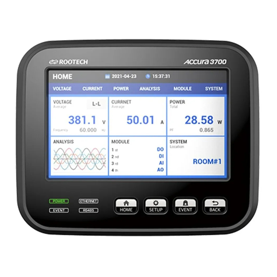
Chapter 3 Operation/Setup Accura 3700 User Guide Display Mode Front View According to hardware revisions of Accura 3700, segments displayed on the device can differ. Fig 3.2 Accura 3700 Front View Voltage Current Active Power Reactive Power Apparent Power Active Energy... -
Page 69: Preparation Time For Start-Up
G: Unit H: Bar Graph Preparation Time for Start-up Accura 3700 needs 10 to 30 seconds to prepare to start the device. During the time, nothing is displayed on the LCD screen. Button Operation In display mode, you can check measurement parameters and the status of each channel of I/O modules. -
Page 70: Full-Screen View In Display Mode
Chapter 3 Operation/Setup Accura 3700 User Guide Full-Screen View in Display Mode Accura 3700 displays information on measurement parameters and operational status of the selected expansion module. The names of the displayed menus differ depending on its hardware revision. Page 70... -
Page 71: Measurement Parameter Screen
By pressing the Up(^) button, you can see measurement values by moving between screens in the reverse direction. Fig 3.4 Voltage/Current/Power Display Screen Per Phase ⓒ 2013 Rootech Inc. All Rights Reserved Page 71... -
Page 72: Fig 3.5 Detailed Line-To-Line Voltage Value Display Screen
NEMA standard appear in sequence. By pressing the Up(^) button, you can see measured values in reverse order. Fig 3.6 Detailed Phase Current Value Display Screen Page 72 ⓒ 2013 Rootech Inc. All Rights Reserved... -
Page 73: Fig 3.7 Detailed Power Value Display Screen
By pressing the Up(^) button, you can see measured values in reverse order. Fig 3.8 Detailed Demand Active Power Value Display Screen ⓒ 2013 Rootech Inc. All Rights Reserved Page 73... -
Page 74: Fig 3.9 Net Energy Display Screen On The Energy Display Screen
I/O expansion modules attached to the rear of Accura 3700. What appears on the screen varies by module number and type. Refer to 「View Expansion Module Status」 section for details. -
Page 75: Fig 3.10 Ethernet Connection Status Display Screen
There is an Ethernet loop including this device. In this case, network disconnection does not occur since the device automatically finds an alternative path even though the port gets disconnected. No.Cn No connection Both ports are disconnected. ⓒ 2013 Rootech Inc. All Rights Reserved Page 75... - Page 76 The above screen shows information on the partner device when the port 1 is connected to Accura device or another device that supports RTSP. The number in the 3rd row indicates the port number of the partner. Page 76 ⓒ 2013 Rootech Inc. All Rights Reserved...
- Page 77 The above screen shows MAC information on the partner device when the port 1 is connected to a device that supports RSTP. Information on the port 2 is shown in the same sequence below the information on the port 1. ⓒ 2013 Rootech Inc. All Rights Reserved Page 77...
-
Page 78: Fig 3.15 Surface Temperature Display Screen
By pressing the Right(>) button again on the INFO/NETWORK display screen, you can move to the ETC screen. The screen shows data on the temperature measured by the temperature sensor attached to the back of Accura 3700, as well as data on the current time. Fig 3.15 Surface Temperature Display Screen Page 78 ⓒ... -
Page 79: Viewing Expansion Module Status
Viewing Expansion Module Status You can check the status of expansion modules of Accura 3700 on the page that shows the number of modules and the ID of each module and on the page that shows the status of channels for each module. - Page 80 The LCD screen shows the channel information on each I/O module and the ID of the corresponding module is shown on the upper side. If there is one module connected to Accura 3700, you can move to the product info/network display screen by pressing the Right(>) button on the screen. If there are more than two connected expansion modules, you can move between screens showing the channel information on connected modules in sequence by pressing the Right(>) button.
-
Page 81: Display Screen For Individual Expansion Modules
Chapter 3 Operation/Setup Display Screen for Individual Expansion Modules The following figure shows the status information on Accura 3700 expansion modules, including DIO, DI, DO, AI, AO, A4D2, A2D4, RTD, ELD, and DC. Each module has specialized functions required in the field. -
Page 82: Fig 3.19 Main Screen Of The Dio Module
B contact point. DO Status Indication DO Contact Point Input Polarity: Normal Input Polarity: Reverse Low (_) Open (Off) Close (On) High(ㅁ) Close (On) Open (Off) Page 82 ⓒ 2013 Rootech Inc. All Rights Reserved... -
Page 83: Fig 3.20 Main Screen Of The Di Module
DO channel state of DIO modules. As the state of 4 channels is displayed on one screen, the state of 6 channels is displayed on two screens. You can check each screen in sequence by using the Up(^) and Down(v) buttons. Fig 3.21 Main Screen of the DO Module ⓒ 2013 Rootech Inc. All Rights Reserved Page 83... -
Page 84: Fig 3.22 Main Screen Of The Ai Module
For example, if it is configured to convert the average current value(0 – 100A) measured by Accura 3700 into 4 – 20mA and to output it to the AO channel, and 50 A current is measured, 12 mA is displayed in the third row and 50 is displayed in the fourth row on the screen. -
Page 85: Fig 3.23 Main Screen Of The Ao Module
Analog output channels have the same functions as the channels of the AO module and digital output channels have the same functions as the channels of the DO module. Fig 3.24 Main Screen of the A4D2 Module ⓒ 2013 Rootech Inc. All Rights Reserved Page 85... -
Page 86: Fig 3.25 Main Screen Of The A2D4 Module
The RTD module has 3 RTD input channels. The resistance value of the RTD and the converted temperature are displayed on one screen per channel. You can check each screen in sequence by using the Up(^) and Down(v) buttons. Fig 3.26 Main Screen of the RTD Module Page 86 ⓒ 2013 Rootech Inc. All Rights Reserved... -
Page 87: Fig 3.27 Main Screen Of The Eld Module
Up(^) and Down(v) buttons. The digital output channel has the same functions as the channels of the DO module. Fig 3.27 Main Screen of the ELD Module ⓒ 2013 Rootech Inc. All Rights Reserved Page 87... -
Page 88: Fig 3.28 Main Screen Of The Dc Module
Digital input channels have the same functions as the channels of the DI module, and the digital output channel has the same functions as the channels of the DO module. Fig 3.28 Main Screen of the DC Module Page 88 ⓒ 2013 Rootech Inc. All Rights Reserved... -
Page 89: Setup Mode
Chapter 3 Operation/Setup Setup Mode Long press the SETUP button and enter setup mode on the LCD screen of Accura 3700 device in order to configure the wiring mode, PT, Ethernet/RS-485 communication, and events of the device and check setup info. -
Page 90: Full Screen In Setup Mode
Full Screen in Setup Mode According to the hardware revision of Accura 3700, the order and name of the setup menu can vary. You can check the hardware revision info through the number that comes after 5A(or 1A) in the fourth row on the screen accessed via the 「INFO >... - Page 91 Accura 3700 User Guide Chapter 3 Operation/Setup ⓒ 2013 Rootech Inc. All Rights Reserved Page 91...
- Page 92 Chapter 3 Operation/Setup Accura 3700 User Guide When the hardware revision number is 9 or higher ◼ Page 92 ⓒ 2013 Rootech Inc. All Rights Reserved...
-
Page 93: Demo
Accura 3700 User Guide Chapter 3 Operation/Setup ⓒ 2013 Rootech Inc. All Rights Reserved Page 93... -
Page 94: Measurement Setup
00000.1 – 99999.9 (default 50.0) Accura 3700-5A (default 10.0) Accura 3700-1A Sc[d][d].[d] CT secondary current rating 00.1 – 99.9 (default 5.0) Accura 3700-5A (default 1.0) Accura 3700-1A 1. d → decimal Page 94 ⓒ 2013 Rootech Inc. All Rights Reserved... - Page 95 CT primary current 00000.1 – 99999.9 (Default 50.0) Accura 3700-5A (Default 10.0) Accura 3700-1A 1. d → decimal Demand Subinterval Setup Range 1 – 60 minutes (default 15 min) Number of Demand Subintervals ⓒ 2013 Rootech Inc. All Rights Reserved Page 95...
- Page 96 Harmonic calculation method (Method 2) Total Power Calculation Method Accura 3700 supports two methods for calculation of the total power based on per-phase power (in case of 3 phase line, the total power for 3 phases). For more details, refer to 「Chapter 4 Measurements > Three-Phase Power Measurement」.
- Page 97 CT which is entered into Accura 3700. If the default value is set to 20mA and the CT whose secondary rating is 5A is used, the current value less than 1/250 of the rating is displayed as 0.
- Page 98 「oFF」. Setup Range on (default) Displays the sign of reactive power according to the phase of the current Does not display the sign of reactive power Page 98 ⓒ 2013 Rootech Inc. All Rights Reserved...
- Page 99 C [d] 3, respectively. (default 123) P (default) Positive Normal current wiring from S(Source) to L(Load) direction П Negative Reverse current wiring from L(Load) to S(Source) direction 1. d → decimal ⓒ 2013 Rootech Inc. All Rights Reserved Page 99...
-
Page 100: Event Setup
Activates the notification function for Dip events Deactivates the notification function for Dip events Swell Event Setup Range on (default) Activates the notification function for Swell events Deactivates the notification function for Swell events Page 100 ⓒ 2013 Rootech Inc. All Rights Reserved... - Page 101 In Case of 3P3W Connection ◼ Setup Range 1.0 – 98.0 % Ratio for the reference voltage (Default 90.0) Display (3P3W) [d][d][d].[d] V/kV Reference voltage(line-to-line voltage) x percentage 1. d → decimal ⓒ 2013 Rootech Inc. All Rights Reserved Page 101...
-
Page 102: Fig 3.29 Dip Event Setup (3P3W)
(default 92.0) Display (3P3W) Reference voltage (Line-to-line voltage) [d][d][d].[d] V/kV x percentage 1. d → decimal Fig 3.29 Dip Event Setup (3P3W) Example of when the reference voltage is set to 380V Page 102 ⓒ 2013 Rootech Inc. All Rights Reserved... -
Page 103: Fig 3.30 Dip Event Setup (3P4W)
In Case of 3P3W Connection ◼ Setup Range 102.0 – 999.0 % Ratio to reference voltage (default 110.0) Display (3P3W) [d][d][d].[d] V/kV Reference voltage (Line-to-line voltage) x percentage 1. d → decimal ⓒ 2013 Rootech Inc. All Rights Reserved Page 103... -
Page 104: Fig 3.31 Swell Event Setup (3P3W)
Display (3P3W) [d][d][d].[d] V/kV Reference voltage (Line to line voltage) x percentage 1. d → decimal Fig 3.31 Swell Event Setup (3P3W) Example of when the reference voltage is set to 380V Page 104 ⓒ 2013 Rootech Inc. All Rights Reserved... -
Page 105: Fig 3.32 Swell Event Setup (3P4W)
When the measured voltage and current values are 0, it is determined as a blackout event. Setup Range Activates the notification function for a blackout event oFF (default) Deactivates the notification function for a blackout event ⓒ 2013 Rootech Inc. All Rights Reserved Page 105... - Page 106 Deactivates the notification function for a temperature event Start Threshold of Temperature Events Setup Range 20 – 9999 ℃ (default: 50) End Threshold of Temperature Events Setup Range 0 – 9998 ℃ (default: 48) Page 106 ⓒ 2013 Rootech Inc. All Rights Reserved...
- Page 107 [d][d].[d][d] A/kA 1. d → decimal End Threshold of Current Events Setup Range 0.0 – 998.0 % Percentage for the end event (default 98) Display [d][d].[d][d] A/kA 1. d → decimal ⓒ 2013 Rootech Inc. All Rights Reserved Page 107...
- Page 108 (default) Deactivates the notification function for a demand current event Start Threshold of Demand Current Events Setup Range 5.0 – 999.0 % (default 70.0) Percentage for the start event Page 108 ⓒ 2013 Rootech Inc. All Rights Reserved...
- Page 109 �� / 2 ∗ �������� �� ∗ �������� ��−�� ��−�� 1P2W �� ∗ �������� �� ∗ �������� ��−�� ��−�� 3. The value up to 100000 kW can be entered via communication. ⓒ 2013 Rootech Inc. All Rights Reserved Page 109...
- Page 110 Voltage Dip Events on 3 Phases Setup Range Activates the notification function for a dip event on three phases oFF (default) Deactivates the notification function for a dip event on three phases Page 110 ⓒ 2013 Rootech Inc. All Rights Reserved...
-
Page 111: Rs-485 Communication Setup
1. Up to 16 devices connected over a distance of 1200m can perform communication at 115200 bps. Parity Bit Setup Range EuEn (default) Even parity nonE None parity Odd parity Stop Bit Setup Range 1 (default) ⓒ 2013 Rootech Inc. All Rights Reserved Page 111... - Page 112 0. RS-485 Communication Map Setup If the communication map is configured as 「a3500」, communication is available with the same map used for the Accura 3500 device manufactured by Rootech. Setup Range a3700 (default) Communication map of Accura 3700...
-
Page 113: Ethernet Communication Setup
Accura 3700 User Guide Chapter 3 Operation/Setup Ethernet Communication Setup Setup Range 000.000.000.000 - 255.255.255.255 (Default 010.010.010.100) Subnet Mask Setup Range 255.255.000.000 - 255.255.255.252 (Default 255.255.255.000) Gateway Setup Range 000.000.000.000 - 255.255.255.255 (Default 010.010.010.001) ⓒ 2013 Rootech Inc. All Rights Reserved Page 113... - Page 114 「Sync」 and complete time synchronization. Setup Range Sync Perform the time synchronization of Accura 3700 device with the NTP server. NTP Server Enter the IP address of the NTP(Network Time Protocol) server for the time synchronization of Accura 3700.
- Page 115 5 – 600 second Timeout time configuration for non- (default 600) asking the Modbus-TCP communication RSTP Setup Range oFF (default) RSTP disabled RSTP enabled DHCP Setup Range oFF (default) DHCP disabled DHCP enabled ⓒ 2013 Rootech Inc. All Rights Reserved Page 115...
-
Page 116: Reset Setup
Demand Reset Setup Range rESEt Demand reset Maximum/Minimum Value Reset The maximum demand value can be reset via this menu. Setup Range rESEt Maximum/minimum value reset Page 116 ⓒ 2013 Rootech Inc. All Rights Reserved... - Page 117 Accura 3700 User Guide Chapter 3 Operation/Setup Energy Reset Setup Range rESEt Energy (kWh, kVARh, kVAh) reset All Reset Setup Range Reset of all items rESEt (Demand, Maximum/Minimum, Energy) ⓒ 2013 Rootech Inc. All Rights Reserved Page 117...
-
Page 118: Display Setup
LCD backlight by checking the event log. Setup Range 0 – 9999 backlight time when an event occurs [minute] (default 0) backlight time (0 : 5 seconds) Пo.oFF Backlight time ∞ Пo.on Backlight time Page 118 ⓒ 2013 Rootech Inc. All Rights Reserved... - Page 119 [%] Blinking Cycle of the LCD Backlight You can set the blinking cycle of the LCD backlight. Setup Range 0.1 – 10.0 (default 1.0) [sec] ⓒ 2013 Rootech Inc. All Rights Reserved Page 119...
- Page 120 The magnitude of current is calculated by multiplying 0.2 A by the CT ratio (2 A is available when the default CT ratio is 10), and the current lags behind the voltage in phase by 60 degrees. Page 120 ⓒ 2013 Rootech Inc. All Rights Reserved...
- Page 121 Swell size: 130% of reference voltage Voltage change after the demo operation: Vref is maintained during 15 cycles→ A swell occurs during 5 cycles → Voltage value is maintained after returning to Vref. ⓒ 2013 Rootech Inc. All Rights Reserved Page 121...
-
Page 122: Module Setup
Make sure to save setup information to the device’s memory after adding or removing modules and changing the module setup for effective module management. Page 122 ⓒ 2013 Rootech Inc. All Rights Reserved... -
Page 123: Setup For Individual Expansion Modules
The following table shows information on the types of Accura 3700 modules and channels for each module. The number of channels vary by module. As it is seen at the chart, there are modules with one type of channel and more than two types of channels. -
Page 124: Full Screen For Module Setup
Chapter 3 Operation/Setup Accura 3700 User Guide Full Screen for Module Setup Page 124 ⓒ 2013 Rootech Inc. All Rights Reserved... -
Page 125: Di Module Setup
10 – 255 ms (default 10) The device detects a change in DI status only if the input state is maintained longer than the set time to prevent it from responding to chatter and noise signals. ⓒ 2013 Rootech Inc. All Rights Reserved Page 125... -
Page 126: Do Module Setup
The state of DO contact point corresponding to the DO display is as the following chart corresponding to configured polarity value. Polarity normal configuration corresponds to the contact point A and polarity reverse configuration corresponds to the contact point B. Page 126 ⓒ 2013 Rootech Inc. All Rights Reserved... - Page 127 ON time setup screens appear in sequence. Once you complete the configuration for timed latches and pulses, you can move to the parameter screen for each DO channel. ⓒ 2013 Rootech Inc. All Rights Reserved Page 127...
- Page 128 The data are displayed only when the DO channel type is set to timed latch mode. Setup Range 1 – 999 (default 60) ON status of the DO channel remains during the set time. [min] Page 128 ⓒ 2013 Rootech Inc. All Rights Reserved...
- Page 129 ㅏ Urh Receive Generates the output signal based on the kVarh preset received reactive energy d ㅏ Urh Delivery Generates the output signal based on the kVarh preset delivered reactive energy ⓒ 2013 Rootech Inc. All Rights Reserved Page 129...
- Page 130 Direct Control for Each DO Channel With the button on the front of Accura 3700, you can directly perform the ON/OFF control of the DO channel. The setup range varies by the selected output type. If energy associated with a pulse output is configured, this function is unavailable.
-
Page 131: Dio Module Setup
[d] channel 1 – 6 The AI module has 6 AI channels. Setup Range 0–20 (default) Input range 0 – 20 mA 4–20 Input range 4 – 20 mA 1. d → decimal ⓒ 2013 Rootech Inc. All Rights Reserved Page 131... - Page 132 (default 20.0) Actual value corresponding to 20mA 1. d → decimal 2. S → Sign. When configuring the sign, select 0(positive number) or −(negative number) by using the Up(^) and Down(v) buttons. Page 132 ⓒ 2013 Rootech Inc. All Rights Reserved...
- Page 133 Setup Range 1, 2, 4, 8, 16, 32 ms Interval used to calculate the average (default 32) value ⓒ 2013 Rootech Inc. All Rights Reserved Page 133...
- Page 134 Setup Range Setup for the sign of input current signals Measured as an absolute value without a sign on (default) Measured as an actual value with a sign Page 134 ⓒ 2013 Rootech Inc. All Rights Reserved...
- Page 135 When input values often exceed and fall below the alarm threshold value for events, it can cause multiple events to occur. Thus, for effective event management, it is necessary to set up a proper hysteresis level. ⓒ 2013 Rootech Inc. All Rights Reserved Page 135...
- Page 136 AI Module Software Version You can check the bootloader and firmware version of the connected AI module on the screen. Setup Range b [d] Bootloader version F [d].[d][d] Firmware version 1. d → decimal Page 136 ⓒ 2013 Rootech Inc. All Rights Reserved...
-
Page 137: Ao Module Setup
ㅏ Uar kVAR Outputs analog signals associated with reactive power[kVAR] ㅏ Ua Outputs analog signals associated with apparent power[kW] FrEq Freq Outputs analog signals associated with frequency[Hz] 1. d → decimal ⓒ 2013 Rootech Inc. All Rights Reserved Page 137... - Page 138 20 mA. For the size of the converted values u1 and u2, u1 can be >u2 or <u2(u1≠u2). 20 − 4 Output Current [ mA ] = ∗ ( Output Value − u1 ) + 4 ��1 − ��2 Page 138 ⓒ 2013 Rootech Inc. All Rights Reserved...
- Page 139 AO Module Software Version You can check the bootloader and firmware versions of the connected AO module on the screen. Display b [d] Bootloader version F [d].[d][d] Firmware version 1. d → decimal ⓒ 2013 Rootech Inc. All Rights Reserved Page 139...
-
Page 140: A4D2 Module Setup
A4D2 Module Software Version You can check the bootloader and firmware version of the connected A4D2 module on the screen. Display b [d] Bootloader version F [d].[d][d] Firmware version 1. d → decimal Page 140 ⓒ 2013 Rootech Inc. All Rights Reserved... -
Page 141: A2D4 Module Setup
A2D4 Module Software Version You can check the bootloader and firmware versions of the connected A2D4 module on the screen. Display b [d] Bootloader version F [d].[d][d] Firmware version 1. d → decimal ⓒ 2013 Rootech Inc. All Rights Reserved Page 141... -
Page 142: Rtd Module Setup
‘Under’ threshold value. 1. The ‘Over’ threshold value is the reference value for the generation of alarms. 2. The ‘Under’ threshold value is obtained by subtracting hysteresis from the ‘Over’ threshold value. Page 142 ⓒ 2013 Rootech Inc. All Rights Reserved... - Page 143 1, 2 (default 100) -200 – 850°C 1. d → decimal 2. S → Sign. When configuring the sign, select 0(positive number) or −(negative number) by using the Up(^) and Down(v) buttons. ⓒ 2013 Rootech Inc. All Rights Reserved Page 143...
- Page 144 RTD Module Software Version You can check the bootloader and firmware versions of the connected RTD module on the screen. Display b [d] Bootloader version F [d].[d][d] Firmware version 1. d → decimal Page 144 ⓒ 2013 Rootech Inc. All Rights Reserved...
-
Page 145: Eld Module Setup
Internal resistance of each voltage-type ZCT product (default 1000) 1 – 9999 (Ohm) b.[d][d][d][d] Burden resistance of each voltage-type ZCT product (default 1200) 1 – 9999 (Ohm) 1. d → decimal ⓒ 2013 Rootech Inc. All Rights Reserved Page 145... - Page 146 When input values often exceed and fall below the alarm threshold value for events, it can cause multiple events to occur. Thus, for effective event management, it is necessary to set up a proper hysteresis level. Page 146 ⓒ 2013 Rootech Inc. All Rights Reserved...
- Page 147 Display do_1 The ELD module has one DO channel. Setup Range norП (default) Closed (normal) when an ON command is issued Open (reverse) when an ON command is issued ⓒ 2013 Rootech Inc. All Rights Reserved Page 147...
-
Page 148: Dc Module Setup
「on」, when the signal with the reverse polarity is input, it is measured as a negative value in proportion to the value. Setup Range Select the measurement method when the voltage signal with reverse polarity is connected to the channel. oFF (default) Page 148 ⓒ 2013 Rootech Inc. All Rights Reserved... - Page 149 When input values often exceed and fall below the alarm threshold value for events, it can cause multiple events to occur. Thus, for effective event management, it is necessary to set up a proper hysteresis level. ⓒ 2013 Rootech Inc. All Rights Reserved Page 149...
- Page 150 Shunt Rating of Rectifier Output Current Setup Range 1 – 999 mV (default 50) Secondary voltage rating of a shunt 1 – 9999 A (default 100) Primary current rating of a shunt Page 150 ⓒ 2013 Rootech Inc. All Rights Reserved...
- Page 151 ‘Under’ threshold value. 1. The Over threshold value is the reference value for the generation of alarms. 2. The Under threshold value is obtained by subtracting hysteresis from the Over threshold value. ⓒ 2013 Rootech Inc. All Rights Reserved Page 151...
- Page 152 The hysteresis value is displayed only when 「oFF」 is not selected as the rectifier output current settings. On the screen shown below, you can set up the hysteresis value. Setup Range 1 – 999 A (default 4) Hysteresis value Page 152 ⓒ 2013 Rootech Inc. All Rights Reserved...
- Page 153 「Under」 threshold value. 1. The Over threshold value is the reference value for the generation of alarms. 2. The Under threshold value is obtained by subtracting hysteresis from the Over threshold value. ⓒ 2013 Rootech Inc. All Rights Reserved Page 153...
- Page 154 The threshold value is displayed only when 「oFF」 is not selected as the rectifier battery event settings. The threshold value is configured as the reference value for event notifications. Setup Range -9999 – 9999 A Threshold value for event notifications (default 100) Page 154 ⓒ 2013 Rootech Inc. All Rights Reserved...
- Page 155 10 – 255 ms (default 10) The device detects a change in DI status only if the input state is maintained longer than the set time to prevent it from responding to chatter and noise signals. ⓒ 2013 Rootech Inc. All Rights Reserved Page 155...
- Page 156 The DC module has one DO channel. Setup Range Closed (normal) when an ON command is issued norП (default) Open (reverse) when an ON command is issued 1. d → decimal Page 156 ⓒ 2013 Rootech Inc. All Rights Reserved...
- Page 157 DC Module Software Version You can check the bootloader and firmware versions of the connected DC module on the screen. Display b [d] Bootloader version F [d].[d][d] Firmware version 1. d → decimal ⓒ 2013 Rootech Inc. All Rights Reserved Page 157...
-
Page 158: Information Setup
1. d → decimal Hardware Version Display [d].[d][d] Hardware version [d]A_[d][d] Hardware revision of Accura 3700-5A/1A 1. d → decimal Software Version Display a[d].[d][d] Application version F[d].[d][d] Firmware version 1. d → decimal Page 158 ⓒ 2013 Rootech Inc. All Rights Reserved... - Page 159 Etc. Setup Fault Test By virtually generating faults through the test, the device allows you to check the fault status of the module and the network via Accura 3700 Modbus Map. Setup Range oFF (default) The test function does not operate.
-
Page 160: Event Mode
Dip(Sag), Swell, Fuse Failure, Blackout, as well as events occurring in the DIO, DI, AI, RTD, ELD, and DC modules. Accura 3700 also notifies users of the event when an error occurs in the redundant channels of the DIO, DI, and DC modules. For event notifications, the EVENT LED on the front of the device Swell and the LCD backlight blink. -
Page 161: Clearing Event Notifications
2. Press the button for more than one second and release it. After one second, beeping sounds are made. Note If there is no button operation for 10 minutes in event mode, the screen automatically returns to display mode. ⓒ 2013 Rootech Inc. All Rights Reserved Page 161... -
Page 162: Event Log Number
Event Timestamp You can select the Event Log screen with the Left(<) and Right(>) buttons. And then you can check the time when the event occurs by pressing the Down(v) button. Page 162 ⓒ 2013 Rootech Inc. All Rights Reserved... -
Page 163: Dip Event Log
Minimum voltage during the dip event [d][d][d][d][d] ms Duration time of a dip event 1. The phase(A, B, C, AB, BC, CA) where the event occurs is displayed. 2. d → decimal ⓒ 2013 Rootech Inc. All Rights Reserved Page 163... -
Page 164: Swell Event Log
Maximum voltage during the swell event [d][d][d] ms Duration time of a swell event 1. The phase(A, B, C, AB, BC, CA) where the event occurs is displayed. 2. d → decimal Page 164 ⓒ 2013 Rootech Inc. All Rights Reserved... - Page 165 B ph.M Phase Open end event generates (Phase B [d][d][d][d][d] ms Phase Open event duration time 1. The phase(A, B, C) where the event occurs is displayed. 2. d → decimal ⓒ 2013 Rootech Inc. All Rights Reserved Page 165...
-
Page 166: Fuse Fail Event Log
A fuse fail event ends (Phase B [d][d][d][d][d] ms Duration time of the fuse fail event 1. The phase(A, B, C) where the event occurs is displayed. 2. d → decimal Page 166 ⓒ 2013 Rootech Inc. All Rights Reserved... -
Page 167: Blackout Event Log
Blackout End Event Log The event log displays the information on when a blackout event ends. Display E[d][d][d] Event number 000 – 999 b.Out A blackout event ends. 1. d → decimal ⓒ 2013 Rootech Inc. All Rights Reserved Page 167... -
Page 168: Event Log Of Di Channels
An event on the open DI channel occurs. Corresponding module name such as DIO, DI, DC, etc. Ch.[d][d] The channel where the event occurs: Channel 1 – 12 1. d → decimal Page 168 ⓒ 2013 Rootech Inc. All Rights Reserved... -
Page 169: Event Log Of Ai Channels
Uout and Iout are displayed for the output voltage channel and the output current channel, respectively. Ibat is displayed for the battery current. 1. d → decimal ⓒ 2013 Rootech Inc. All Rights Reserved Page 169... -
Page 170: Event Log Of Open Rtd Sensor
Event number 000 – 999 oPEn An open event on the RTD module occurs. RTD module name Ch.[d] The channel where the event occurs: Channel 1 – 3 1. d → decimal Page 170 ⓒ 2013 Rootech Inc. All Rights Reserved... - Page 171 Accura 3700 User Guide Chapter 3 Operation/Setup Over-Temperature Event Log Over-Temperature Start Event Log The event log displays the information when the temperature of Accura 3700 device starts to increase. Display E[d][d][d] Event number 000 – 999 tПP.S An over temperature event starts.
- Page 172 The phase where the overcurrent event ends (Phase B [d][d][d][d] A Maximum current during the event [d][d][d][d][d] ms Event duration time 1. The phase(A, B, C) where the event occurs is displayed. 2. d → decimal Page 172 ⓒ 2013 Rootech Inc. All Rights Reserved...
- Page 173 Demand overcurrent end event (Phase B [d][d][d][d] A Maximum current during the event [d][d][d][d][d] Event duration time [minute] 1. The phase(A, B, C) where the event occurs is displayed. 2. d → decimal ⓒ 2013 Rootech Inc. All Rights Reserved Page 173...
- Page 174 The phase where the overpower event ends (Phase [d][d][d][d] kW Maximum power during the event [d][d][d][d][d] ms Event duration time 1. The phase(A, B, C, TOT) where the event occurs is displayed. 2. d → decimal Page 174 ⓒ 2013 Rootech Inc. All Rights Reserved...
-
Page 175: User-Triggered Event Log
1. d → decimal 2. c → A – E(text) No Event Logs When there are no event logs saved, the following text appears on the screen. Display No event logs Eunt ⓒ 2013 Rootech Inc. All Rights Reserved Page 175... -
Page 176: Required Setup Steps
Chapter 3 Operation/Setup Accura 3700 User Guide Required Setup Steps For normal operations of Accura 3700, it is required to take the following steps. Wiring Method The default setting is three phase 4 wire configuration. In order to change the wiring method, follow the steps below(an example of three phase 3 wire connection). - Page 177 3. The rated primary and secondary current values of the CT are used to determine the ratio needed for measuring the current. 4. It is used as the reference voltage for Dip/Swell event setup. 5. It is used as the reference value of the bar graph appearing on the screen. ⓒ 2013 Rootech Inc. All Rights Reserved Page 177...
-
Page 178: Chapter 4 Measurements
The maximum and minimum values Accura 3700 provides after resetting the values are stored in the nonvolatile memory. Thus, the values are preserved even when Accura 3700 is turned on after it is turned off. The peak demand value is cleared to zero by resetting the maximum/minimum values, not demand values. - Page 179 , you can select the rated current(default) or peak demand current(only available via communication). For the I 3. Residual voltage is the RMS voltage value calculated by adding up three-phase voltages. �� �������� 4. Crest factor: �� ������ ⓒ 2013 Rootech Inc. All Rights Reserved Page 179...
- Page 180 RMS current value calculated by adding up three-phase currents. 7. It indicates the values for line-to-neutral voltages in 3-phase 4-wire connection and values for line-to-line voltages in 3-phase 3-wire connection. Page 180 ⓒ 2013 Rootech Inc. All Rights Reserved...
-
Page 181: Measurement Event
Measurement Event The following table shows the measurement events provided by Accura 3700. Through the event log mode of Accura 3700, you can check detailed data on the last 500 event logs, including the events that recently occurred. ▣ Shown on Accura 3700 Screen & Available via Communication ▲... -
Page 182: Measurements According To Voltage Wiring
– V voltage of the device Available Measurement Data Item Line-to-neutral Voltage(rms) Line-to-line Voltage(rms) Current(rms) Active Power Phase A * PF Phase B * PF Phase C * PF Average/ Total Page 182 ⓒ 2013 Rootech Inc. All Rights Reserved... -
Page 183: 3-Phase 3-Wire
Voltage Connection You can use 2 or 3 PTs in 3-phase 3-wire connection. Its installation cost differs according to the number of PTs. However, regardless of how many PTs are used, Accura 3700 performs measurements in the same way. You can also use 2 or 3 CTs in 3-phase 3-wire connection for three-phase measurement. A benefit from using 3 CTs instead of 2 CTs is that it allows you to detect leakage current by calculating residual current through the sum of three-phase currents. - Page 184 However, by using a virtual neutral point where the residual voltage value of three-phase voltages becomes zero, you can calculate voltage and power values for each phase. Page 184 ⓒ 2013 Rootech Inc. All Rights Reserved...
-
Page 185: 1-Phase 3-Wire
= 0 (The value becomes 0 in 1P3W connection) – V Available Measurement Data Item Line-to-Neutral Voltage[rms] Line-to-Line Voltage[rms] Current[rms] Active Power Phase A * PF Phase B Phase C * PF Average/ Total ⓒ 2013 Rootech Inc. All Rights Reserved Page 185... -
Page 186: 1-Phase 2-Wire
= 0 (The value becomes 0 in 1P2W connection) Available Measurement Data Item Line-to-Neutral Voltage[rms] Line-to-Line Voltage[rms] Current[rms] Active Power Phase A * PF Phase B Phase C Average /Total Page 186 ⓒ 2013 Rootech Inc. All Rights Reserved... -
Page 187: Measurement Of Voltage Dip(Sag)/Swell
Dip duration Dip start time Dip end time 1-cycle RMS 220.0 220.0 173.8 110.0 110.0 110.0 173.8 220.0 220.0 Dip start voltage Dip end voltage Dip peak voltage (Max. Residual Voltage) ⓒ 2013 Rootech Inc. All Rights Reserved Page 187... -
Page 188: Residual Voltage Measurement
3-phase system, it is equal to the RMS value calculated by adding up 3-phase currents. where �� = 3 ∗ �� �� ∶ zero − sequence current component ������ Refer to 「Negative-/Zero-sequence Unbalance」 for details about the zero-sequence component of current. Page 188 ⓒ 2013 Rootech Inc. All Rights Reserved... -
Page 189: Power Measurement Per Phase
The sign of reactive power is the same as the sign of reactive power calculated with the fundamental calculation method. where k=a,b,c �� = ±√�� − �� �� �� �� ⓒ 2013 Rootech Inc. All Rights Reserved Page 189... -
Page 190: Three-Phase Power Measurements
The total apparent power is calculated based on the vector sum of the total active power and reactive power. (Vector sum) �� = √�� + �� �� �� �� Fig 4.7 Vector Sum for the Total Apparent Power | St | Page 190 ⓒ 2013 Rootech Inc. All Rights Reserved... -
Page 191: Power Factor(Pf) Measurement
0, the power factor cannot be calculated. In this case, it can be set to 1.0 or 0.0, and the default value is 1.0. �� �� �� �� �� �� ���� ���� ���� �� �� �� �� �� �� �� �� �� �� �� ���� �� �� �� ⓒ 2013 Rootech Inc. All Rights Reserved Page 191... -
Page 192: Phase Angle Measurement
-0.0 +0.0 Note If the current leads or lags the voltage, Accura 3700 displays the phase angle as LEAD or LAG on its screen. If the reactive power is zero, the phase angle is not displayed. Page 192 ⓒ 2013 Rootech Inc. All Rights Reserved... -
Page 193: Demand Measurement
100 − (��ℎ���������� ���������������� ����������) ∙ 60 [ ������ ] �� = ∙ �� ������ If the thermal time constant τ is less than 1 second, it is calculated as 1 second. ⓒ 2013 Rootech Inc. All Rights Reserved Page 193... - Page 194 Avg 2.6 Avg 3.0 Avg 4.0 Avg 4.4 1:15 1:20 1:25 1:30 1:35 time (4.8+2.6+3.0)/3 (2.6+3.0+4.0)/3 demand output 3.47 3.20 (updated every T (3.0+4.0+4.4)/3 prediction demand output 3.80 (updated every second) Page 194 ⓒ 2013 Rootech Inc. All Rights Reserved...
-
Page 195: Voltage Harmonics
128 samples per cycle are used for analysis of current harmonics, and the THD is calculated with harmonics up to the 63rd order. √∑ �� ��=2 �� THD = where I : fundamental current, I : k-th harmonic current �� Fig 4.13 Current Data Processing with the FFT ⓒ 2013 Rootech Inc. All Rights Reserved Page 195... -
Page 196: Unbalance(Nema Mg1)
����ℎ, ������ Average value of three-phase currents Iph,avg: Maximum difference between the three-phase current value and the average value of three- Max(ΔIph): phase currents ∣ Current – the average current ∣ Page 196 ⓒ 2013 Rootech Inc. All Rights Reserved... -
Page 197: Negative-Sequence/Zero-Sequence Unbalance
���������������� − ���������������� ������������������ = × 100 [%] �� Zero-Sequence Unbalance This is the ratio of the zero-sequence component to the positive-sequence component. �� �������� − ���������������� ������������������ = × 100 [%] �� ⓒ 2013 Rootech Inc. All Rights Reserved Page 197... -
Page 198: Aggregation
Fig 4.15 Aggregation Process Fixed Aggregation Accura 3700 provides six fixed aggregation intervals from Aggregation 1 through 6(1 second, 5 seconds, 1 minute, 5 minutes, 1 hour, and 6 hours). In the fixed aggregation interval, the offset time for the start time of the aggregation interval is fixed to zero. - Page 199 Chapter 4 Measurements Custom Aggregation Accura 3700 provides five custom aggregation intervals from Aggregation 11 to 15 that allow the user to arbitrarily set the offset time for the aggregation interval and the start time. If the offset setting is 0, the start of the aggregation interval corresponds to 0: 0: 0: 0. For example, if you...
-
Page 200: Appendix A Specifications
Appendix A Specifications Accura 3700 User Guide Appendix A Specifications Accura 3700 Digital Power Quality Meter Measured Voltage Input Measuring range AC 60 – 500 V L-L(Line-to-Line) voltage (Accuracy guaranteed) Minimum measured value AC 5 V L-N(Line-to-Neutral) voltage Maximum rating 1.1 x maximum measurement range... - Page 201 1. It indicates the peak AC / DC value, and a maximum current of 1 A is the current that can flow at a time during the current carrying time of 100 ms. 2. The default shunt resistance is 50 mV/100 A, and it can be set. ⓒ 2013 Rootech Inc. All Rights Reserved Page 201...
-
Page 202: Appendix B Standards
Power frequency magnetic field immunity IEC 61000-4-11 Voltage dips, short interruptions and voltage variations immunity Certification UL 61010-1 EN 61326-1, EN 61326-2-1 KN 22, KN 24 Part15 B General Warranty period 2 years Page 202 ⓒ 2013 Rootech Inc. All Rights Reserved... -
Page 203: Appendix C Accuracy/Reliability
1. Class 0.2S indicates IEC 62053-22 Class 0.2S. 2. It is not displayed on the LCD screen of Accura 3700 and is only available via communication. 3. It is displayed as x1000 kW/kVar/kVA on the LCD screen of Accura 3700. -
Page 204: Reliability
�� 3. It is not displayed on the LCD screen of Accura 3700 and is only available via communication. IEC62053-22, Electricity Metering Equipment for Active Energy(Class 0.2S) -
Page 205: Appendix D Ordering Information
1 DC voltage input channel, 2 DC current input channels 4 DI channels, 1 DO channel 1. It is not for fire monitoring, but for reference only(Accura 3700 has a temperature sensor on the side of the device). ⓒ 2013 Rootech Inc. All Rights Reserved... - Page 206 ⓒ 2013 Rootech Inc. All Rights Reserved Accura EMeter, Accura 2300/2350, Accura 2300S/2350, Accura 2700/2750, Accura 3000, Accura 3300E, Accura 3300S/3300, Accura 3500S/3500, Accura 3550S/3550, Accura 3700, Accura 5500, Accura 7500 are trademarks of Rootech Inc. Contact us for detailed product specifications and ordering information.
Need help?
Do you have a question about the ACCURA 3700 and is the answer not in the manual?
Questions and answers