Sign In
Upload
Manuals
Brands
ROOTECH Manuals
Measuring Instruments
ACCURA 3700 Series
ROOTECH ACCURA 3700 Series Manuals
Manuals and User Guides for ROOTECH ACCURA 3700 Series. We have
3
ROOTECH ACCURA 3700 Series manuals available for free PDF download: User Manual
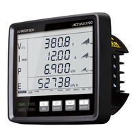
ROOTECH ACCURA 3700 Series User Manual (206 pages)
High Accuracy Digital Power Quality Meter
Brand:
ROOTECH
| Category:
Measuring Instruments
| Size: 13 MB
Table of Contents
Table of Contents
8
Chapter 1 Product Introduction
15
Overview
15
Applications
17
Product Information
18
Product Features
19
Chapter 2 Installation
22
Conditions for Installation
22
Before Installation
23
Product Appearance
23
Fig 2.1 Accura 3700 Front
23
Fig 2.3 Accura 3700 Rear
23
Fig 2.4 Accura 3700 DIO Module
24
Fig 2.6 Accura 3700 DO Module
24
Fig 2.8 Accura 3700 AO Module
24
Fig 2.10 Accura 3700 A2D4 Module
25
Fig 2.12 Accura 3700 ELD Module
25
Components
26
Dimensions
26
Fig 2.14 Accura 3700 Components
26
Fig 2.15 I/O Module Components
26
Fig 2.16 Accura 3700 Front
26
Fig 2.17 Accura 3700 Rear
26
Fig 2.18 Accura 3700 Side
27
Fig 2.19 Accura 3700 I/O Module Front/Side/Height
27
Step 1: Panel Mounting
28
Panel Mounting of Accura 3700
28
Fig 2.20 Panel Mounting of Accura 3700 (ANSI 4")
28
Fig 2.21 Panel Mounting of Accura 3700 (DIN96)
28
Step 2: Voltage/Current Input Wiring
29
Fig 2.22 Voltage/Current Input Wiring
29
Fig 2.23 3P4W Connection with 3 Pts and 3 Cts
31
Fig 2.24 3P3W Connection with 2 Pts and 3 Cts
32
Fig 2.25 3P3W Connection with 2 Pts and 2 Cts
32
Fig 2.26 1P3W Connection with 2 Pts and 2 Cts
33
Fig 2.27 1P2W Connection with 1 PT and 1 CT
33
Fig 2.28 3P4W Direct Voltage Connection with 3 Cts
34
Fig 2.29 3P3W Direct Voltage Connection with 3 Cts
34
Fig 2.30 3P3W Direct Voltage Connection with 2 Cts
35
Fig 2.31 1P3W Direct Voltage Connection with 2 Cts
35
Fig 2.32 1P2W Direct Voltage Connection with 1 CT
36
Step 3: Connections of Accura 3700 Modules for External Communication
37
Ethernet Communication
37
Fig 2.33 Accura 3700 Ethernet Communication Ports
37
Fig 2.34 Accura 3700 Ehternet Connection
38
RS-485 Communication
39
Fig 2.35 RS-485 Communication of Accura 3700
39
Fig 2.36 Connection of Accura 3700 Devices for RS-485 Communication
39
Step 4: Power Supply/Ground Connection of Accura 3700
41
Power Supply Connection
41
Ground Connection
41
Fig 2.37 Power Supply Connection of Accura 3700
41
Step 5: Attaching Expansion Modules to Accura 3700
42
Fig 2.38 I/O Module Attachment
42
Step 6: Wiring I/O Modules
43
DIO Module
43
Fig 2.39 DIO Module
43
Fig 2.40 Digital Input (Redundant Input Structure)
44
Fig 2.41 DC Relay Application
45
Fig 2.42 AC Relay Application
46
DI Module
47
Fig 2.43 DI Module
47
Fig 2.44 Digital Input (Redundant Input Structure)
48
DO Module
49
Fig 2.45 DO Module
49
Fig 2.46 DC Relay Application
50
Fig 2.47 AC Relay Application
50
AI Module
51
Fig 2.48 AI Module
51
Fig 2.49 Analog Input
51
AO Module
52
Fig 2.50 AO Module
52
Fig 2.51 Analog Output of AO Module
52
A4D2/A2D4 Module
53
Fig 2.52 A4D2 Module
53
Fig 2.53 A2D4 Module
53
Fig 2.54 Analog Output of A4D2/A2D4 Module
54
Fig 2.55 DC Relay Application
55
Fig 2.56 AC Relay Application
56
RTD Module
57
Fig 2.57 RTD Module
57
Fig 2.58 RTD Input
58
ELD Module
59
Fig 2.59 ELD Module
59
Fig 2.60 ZCT Input
59
Fig 2.61 DC Relay Application
61
Fig 2.62 AC Relay Application
61
DC Module
62
Fig 2.63 DC Module
62
Fig 2.65 Digital Input(Redundant Input Structure)
63
Fig 2.66 DC Relay Application
65
Fig 2.67 AC Relay Application
65
Chapter 3 Operation/Setup
66
LED Status Indicators
66
Fig 3.1 Accura 3700 Front
66
LCD Control Buttons
67
Display Mode
68
Front View
68
Fig 3.2 Accura 3700 Front View
68
Preparation Time for Start-Up
69
Button Operation
69
Full-Screen View in Display Mode
70
Measurement Parameter Screen
71
Fig 3.3 Main Screen in Display Mode
71
Fig 3.4 Voltage/Current/Power Display Screen Per Phase
71
Fig 3.5 Detailed Line-To-Line Voltage Value Display Screen
72
Fig 3.6 Detailed Phase Current Value Display Screen
72
Fig 3.7 Detailed Power Value Display Screen
73
Fig 3.8 Detailed Demand Active Power Value Display Screen
73
Fig 3.9 NET Energy Display Screen on the Energy Display Screen
74
Fig 3.10 Ethernet Connection Status Display Screen
75
Fig 3.15 Surface Temperature Display Screen
78
Viewing Expansion Module Status
79
Fig 3.16 Module Page Screen Showing the ID of the Expansion Module
79
Fig 3.17 Module Page Screen Showing the Channel Info of the 1St Expansion Module(Ex: DIO Module)
79
Display Screen for Individual Expansion Modules
81
Fig 3.19 Main Screen of the DIO Module
82
Fig 3.20 Main Screen of the DI Module
83
Fig 3.21 Main Screen of the DO Module
83
Fig 3.22 Main Screen of the AI Module
84
Fig 3.23 Main Screen of the AO Module
85
Fig 3.24 Main Screen of the A4D2 Module
85
Fig 3.25 Main Screen of the A2D4 Module
86
Fig 3.26 Main Screen of the RTD Module
86
Fig 3.27 Main Screen of the ELD Module
87
Fig 3.28 Main Screen of the DC Module
88
Setup Mode
89
Button Operation
89
Full Screen in Setup Mode
90
Demo
93
Measurement Setup
94
Event Setup
100
Fig 3.29 Dip Event Setup (3P3W)
102
Fig 3.30 Dip Event Setup (3P4W)
103
Fig 3.31 Swell Event Setup (3P3W)
104
Fig 3.32 Swell Event Setup (3P4W)
105
RS-485 Communication Setup
111
Ethernet Communication Setup
113
Reset Setup
116
Display Setup
118
Module Setup
122
Setup for Individual Expansion Modules
123
Full Screen for Module Setup
124
DI Module Setup
125
DO Module Setup
126
DIO Module Setup
131
AI Module Setup
131
AO Module Setup
137
A4D2 Module Setup
140
A2D4 Module Setup
141
RTD Module Setup
142
ELD Module Setup
145
DC Module Setup
148
Information Setup
158
Event Mode
160
Event Notifications
160
Fig 3.28 Dip(Sag) Event Notification Screen
160
Fig 3.29 Swell Event Notification Screen
160
Clearing Event Notifications
161
Button Operation
161
Event Log Number
162
Event Timestamp
162
Fig 3.30 Example of the Event Log Number
162
Dip Event Log
163
Swell Event Log
164
Fuse Fail Event Log
166
Blackout Event Log
167
Event Log of DI Channels
168
Event Log of AI Channels
169
Event Log of Open RTD Sensor
170
User-Triggered Event Log
175
3-Phase Dip Event Log
175
No Event Logs
175
Required Setup Steps
176
Chapter 4 Measurements
178
General Measurement
178
Measurement Event
181
Measurements According to Voltage Wiring
182
3-Phase 4-Wire
182
Fig 4.1 3P4W Connection with 3 Pts and 3 Cts
182
3-Phase 3-Wire
183
Fig 4.2 3P3W Connection with 2 Pts and 3 Cts
183
1-Phase 3-Wire
185
Fig 4.3 1P3W Connection with 2 Pts and 2 Cts
185
1-Phase 2-Wire
186
Fig 4.4 1P2W Connection with 1 PT and 1 CT
186
Measurement of Voltage Dip(Sag)/Swell
187
Fig 4.5 Calculation of 1-Cycle RMS Values Refreshed each Half Cycle
187
Fig 4.6 Voltage Dip(Sag) Detection
187
Residual Voltage Measurement
188
Residual Current Measurement
188
Power Measurement Per Phase
189
Three-Phase Power Measurements
190
Fig 4.7 Vector Sum for the Total Apparent Power
190
Power Factor(PF) Measurement
191
Fig 4.8 Arithmetic Sum for the Total Apparent Power
191
Phase Angle Measurement
192
Fig 4.9 PF Sign and Phase Angle (Leading/Lagging)
192
Demand Measurement
193
Fig 4.10 Demand Calculation
193
Voltage Harmonics
195
Current Harmonics
195
Unbalance(Nema MG1)
196
Negative-Sequence/Zero-Sequence Unbalance
197
Aggregation
198
Appendix A Specifications
200
Appendix B Standards
202
Appendix C Accuracy/Reliability
203
Accuracy
203
Reliability
204
Appendix D Ordering Information
205
Advertisement
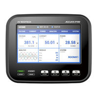
ROOTECH ACCURA 3700 Series User Manual (168 pages)
High Accuracy Digital Power Quality Meter, Installed at multiple locations within a facility, Actually makes possible power quality measurement
Brand:
ROOTECH
| Category:
Measuring Instruments
| Size: 11 MB
Table of Contents
Table of Contents
9
Chapter 1 Introduction
14
Overview
14
Application
16
Device Lineup
17
Features
18
Chapter 2 Installation
21
Environmental Conditions
21
Before You Begin
21
Meter Overview
21
Fig 2.1 Accura 3700 Front
21
Fig 2.3 Accura 3700 Rear
22
Fig 2.4 Accura 3700 DIO Module
23
Fig 2.6 Accura 3700 DO Module
23
Fig 2.8 Accura 3700 AO Module
23
Fig 2.10 Accura 3700 A2D4 Module
24
Fig 2.12 Accura 3700 ELD Module
24
Components
25
Fig 2.14 Accura 3700 Components
25
Fig 2.15 I/O Module Components
25
Dimension
26
Fig 2.16 Accura 3700 Front Dimension
26
Fig 2.18 Accura 3700 Side Dimension
26
Fig 2.19 Accura 3700 I/O Module
26
Step 1: Panel Mounting
28
Accura 3700 Panel Mounting
28
Fig 2.20 Accura 3700 Mounting[Ansi 4"]
28
Step 2: Voltage/Current Wiring
29
Fig 2.22 Voltage/Current Wiring
29
Fig 2.23 3 Phase 4 Wire 3PT, 3CT Wiring, Wiring Mode[Conn] = 3P4U
31
Fig 2.24 3 Phase 3 Wire 2PT 3CT Wiring, Wiring Mode[Conn] = 3P3U
32
Fig 2.25 3 Phase 3 Wire 2PT, 2CT Wiring, Wiring Mode[Conn] = 3P3U
32
Fig 2.26 1 Phase 3 Wire 2PT 2CT Wiring, Wiring Mode[Conn] = 1P3U
33
Fig 2.27 1 Phase 2 Wire 1PT 1CT Wiring, Wiring Mode[Conn] = 1P2U
33
Fig 2.28 3 Phase 4 Wire Direct 3CT Wiring, Wiring Mode[Conn] =3P4U
34
Fig 2.29 3 Phase 3 Wire Voltage Direct 3CT Wiring, Wiring Mode[Conn]=3P3U
34
Fig 2.30 3 Phase 3 Wire Voltage Direct 2CT Wiring, Wiring Mode[Conn]=3P3U
35
Fig 2.31 1 Phase 3 Wire Voltage Direct 2CT Wiring, Wiring Mode[Conn]=1P3U
35
Fig 2.32 1 Phase 3 Wire Voltage Direct 1CT Wiring, Wiring Mode[Conn]=1P2U
36
Step 3: Accura 3700 External Communication
37
Ethernet Communication
37
Fig 2.33 Accura 3700 Ethernet Communication Port
37
Fig 2.34 Accura 3700 Ehternet Connection
38
RS-485 Communication
39
Fig 2.35 Accura 3700 RS-485 Communication
39
Fig 2.36 Accura 3700 RS-485 Communication Connection
39
Step 4: Accura 3700 Power Supply/Ground
40
Power Supply
40
Ground Terminal
40
Fig 2.37 Accura 3700 Power Supply
40
Step 5: Accura 3700 Extension Module Addition
41
Fig 2.38 I/O Module Addition
41
Step 6: I/O Module
42
DIO Module
42
Fig 2.39 DIO Module
42
Fig 2.41 DC Relay Application
44
Fig 2.42 AC Relay Application
44
DI Module
45
Fig 2.43 DI Module
45
DO Module
47
Fig 2.45 DO Module
47
Fig 2.46 DC Relay Application
48
Fig 2.47 AC Relay Application
48
AI Module
49
Fig 2.48 AI Module
49
AO Module
50
Fig 2.50 AO Module
50
Fig 2.51 AO Module Analog Output
50
A4D2/A2D4 Module
51
Fig 2.52 A4D2 Module
51
Fig 2.54 A4D2/A2D4 Module Analog Output
52
Fig 2.55 DC Relay Application
53
Fig 2.56 AC Relay Application
54
RTD Module
55
Fig 2.57 RTD Module
55
Fig 2.58 RTD Input
55
ELD Module
57
Fig 2.59 ELD Module
57
Fig 2.61 DC Relay Application
59
Fig 2.62 AC Relay Application
59
DC Module
60
Fig 2.63 DC Module
60
Fig 2.66 DC Relay Application
63
Fig 2.67 AC Relay Application
63
Chapter 3 Operation/Setup
64
Led
64
Button Function
64
Fig 3.1 Accura 3700 Front Composition
64
Fig 3.2 DISPLAY Mode Screen Example
65
Fig 3.3 SETUP Mode Screen Example
65
Fig 3.4 Event Mode Screen Example
66
Display Mode
68
Front View
68
Fig 3.5 Accura 3700 Front Overview
68
Display Screen
70
Measurement Parameter Display Screen
71
Fig 3.6 First Screen of Display Mode
71
Fig 3.7 Voltage/Current/Power Display Screen for each Phase
71
Fig 3.8 Line to Line Voltage Specific Measurement Value Display Screen
72
Fig 3.9 Line to Neutral Current Specific Measurement Value Display Screen
72
Fig 3.10 Power Specific Measurement Value Display Screen
73
Fig 3.11 Demand Active Power Specific Measurement Value Display Screen
73
Fig 3.12 NET Energy Display Screen in Energy Display Screen
74
Fig 3.13 Ethernet Connection State Display Screen
74
Fig 3.14 Temperature Display Screen in ETC Display Screen
75
Extension Module State View
76
Fig 3.15 First Screen Displaying ID of the Extension Module
76
Fig 3.16 Display Screen of Extension Module[Ex: DIO Module] in Module Screen
76
Fig 3.17 Display Screen of the Second Extension Module in Module Screen
77
Display Screen for Classification of Extension Modules
78
Fig 3.18 DIO Module First Screen
79
Fig 3.19 DI Module First Screen
80
Fig 3.20 DO Module First Screen
80
Fig 3.21 AI Module First Screen
81
Fig 3.22 AO Module First Screen
82
Fig 3.23 A4D2 Module First Screen
82
Fig 3.24 A2D4 Module First Screen
83
Fig 3.25 RTD Module First Screen
83
Fig 3.26 ELD Module First Screen
84
Fig 3.27 DC Module First Screen
84
Event Mode
85
Fig 3.28 Dip[Sag] Event Alarm Screen
85
Fig 3.29 Swell Event Alarm Screen
85
Fig 3.30 Event Log Number Example
87
Setup Mode
93
Setup Menu
94
METER Setup
95
Fig 3.31 Demand Measuring Method
97
Fig 3.32 Power Sign[General Calculation]
98
Fig 3.33 Difference between Two Methods that Calculate each Phase Sum Power
100
Event Setup
103
Fig 3.34 Dip Event Setup[3P3U]
105
Fig 3.35 Dip Event Setup[3P4U]
105
Fig 3.36 Swell Event Setup[3P3U]
107
Fig 3.37 Swell Event Setup[3P4U]
107
RS-485 Communication Setup
109
ETHERNET Communication Setup
110
RESET Setup
113
Display Setup
115
Extension Module ID Setup [MODULE]
118
Individual Extension Module Setup
120
Module Setup Screen
121
DI Module Setup [DIDI]
122
DO Module Setup [DoDo]
123
DIO Module Setup [DioDio]
128
AI Module Setup [AI AI]
128
AO Module Setup [Ao AO]
133
A4D2 Module Setup [MODULE] [A4D2 A4D2]
136
A2D4 Module Setup [A2D4A2D4]
137
RTD Module Setup [RtdRtd]
138
ELD Module Setup [EldEld]
141
DC Module Setup [DCDC]
145
Information [InfoInformation]
154
Required Configuration Step
155
Accura 3700 Voltage Wiring, PT Rating Configuration
155
APPENDIX A Specification
158
APPENDIX B Standard Compliance
160
APPENDIX C Accuracy/Reliability
161
Accuracy
161
Reliability
162
APPENDIX D Ordering Information
163
Index
164
ROOTECH ACCURA 3700 Series User Manual (178 pages)
High Accuracy Digital Power Quality Meter
Brand:
ROOTECH
| Category:
Measuring Instruments
| Size: 7 MB
Table of Contents
Table of Contents
9
Chapter 1 Introduction
15
Overview
15
Application
17
Device Lineup
18
Device Lineup
19
Chapter 2 Installation
24
Environmental Conditions
24
Before Installation
25
Meter Overview
25
Fig 2.4 Accura 3700 DIO Module
26
Fig 2.10 Accura 3700 A2D4 Module
27
Components
28
Dimension
29
Step 1: Panel Installation
31
Step 2: Voltage/Current Wiring
32
Fig 2.23 3 Phase 4 Wire 3PT, 3CT Wiring, Wiring Mode[Conn] = 3P4U
34
Fig 2.24 3 Phase 3 Wire 2PT 3CT Wiring, Wiring Mode[Conn] = 3P3U
35
Fig 2.26 1 Phase 3 Wire 2PT 2CT Wiring, Wiring Mode[Conn] = 1P3U
36
Fig 2.28 3 Phase 4 Wire Direct 3CT Wiring, Wiring Mode[Conn] =3P4U
37
Fig 2.30 3 Phase 3 Wire Voltage Direct 2CT Wiring, Wiring Mode[Conn]=3P3U
38
Fig 2.32 1 Phase 3 Wire Voltage Direct 1CT Wiring, Wiring Mode[Conn]=1P2U
39
Step 3: Accura 3700 External Communication
40
Ethernet Communication
40
Fig 2.34 Accura 3700 Ehternet Connection
41
RS485 Communication
42
Fig 2.35 Accura 3700 RS485 Communication
42
Fig 2.36 Accura 3700 RS485 Communication Connection
42
Step 4: Accura 3700 Power Supply/Ground
43
Power Wiring
43
Ground Terminal
43
Fig 2.37 Accura 3700 Power Supply
43
Step 5: Accura 3700 Extension Module Addition
44
Fig 2.38 I/O Module Addition
44
Step 6: I/O Module
45
DIO Module
45
Fig 2.39 DIO Module
45
Fig 2.40 Digital Input (Dual Input Structure)
46
Fig 2.41 DC Relay Application
47
Fig 2.42 AC Relay Application
47
DI Module
48
Fig 2.43 DI Module
48
Fig 2.44 Digital Input (Dual Input Structure)
49
DO Module
50
Fig 2.45 DO Module
50
Fig 2.46 DC Relay Application
51
Fig 2.47 AC Relay Application
51
AI Module
52
Fig 2.48 AI Module
52
Fig 2.49 Analog Input
52
AO Module
53
Fig 2.50 AO Module
53
Fig 2.51 AO Module Analog Output
53
A4D2/A2D4 Module
54
Fig 2.52 A4D2 Module
54
Fig 2.53 A2D4 Module
54
Fig 2.54 A4D2/A2D4 Module Analog Output
55
Fig 2.55 DC Relay Application
56
Fig 2.56 AC Relay Application
57
RTD Module
58
Fig 2.57 RTD Module
58
Fig 2.58 RTD Input
59
ELD Module
60
Fig 2.59 ELD Module
60
Fig 2.60 ELD Input
60
Fig 2.61 DC Relay Application
62
Fig 2.62 AC Relay Application
62
DC Module
63
Fig 2.63 DC Module
63
Fig 2.64 DC Voltage/Current
63
Fig 2.65 Digital Input(Dual Input Structure)
64
Fig 2.66 DC Relay Application
66
Fig 2.67 AC Relay Application
66
Chapter 3 Operation/Setup
67
Led
67
Fig 3.1 Accura 3700 Front Side Composition
67
Fig 3.2 DISPLAY Mode Screen Example
68
Fig 3.3 SETUP Mode Screen Example
68
Fig 3.4 Event Mode Screen Example
69
Display Mode
71
Front View
71
Fig 3.5 Accura 3700 Front Side Overview
71
Display Screen
73
Measurement Parameter Display Screen
74
Fig 3.6 First Screen of Display Mode
74
Fig 3.7 Line to Neutral Voltage/Current/Power Display Screen
74
Fig 3.8 Specific Measured Value Line to Line Voltage Display Screen
75
Fig 3.9 Specific Measured Value of Line to Neutral Current Display Screen
75
Fig 3.10 Power Specific Measure Value Display Screen
76
Fig 3.11 Demand Effective Power Specific Measure Value Display Screen
76
Fig 3.12 NET Energy Display Screen
77
Fig 3.13 Ethernet Connection State Display Screen
77
Fig 3.14 Temperature Display Screen of ETC
78
Extension Module State View
79
Fig 3.15 First Screen that Displays ID of Extension Module
79
Fig 3.16 Among Module Pages, Screen Displaying Channel Information of Extension Module
79
Module
80
Display Screen for Classification of Extension Modules
81
Fig 3.18 DIO Module First Screen
82
Fig 3.19 DI Module First Screen
83
Fig 3.20 DO Module First Screen
83
Fig 3.21 AI Module First Screen
84
Fig 3.22 AO Module First Screen
85
Fig 3.23 A4D2 Module First Screen
85
Fig 3.24 A2D4 Module First Screen
86
Fig 3.25 RTD Module First Screen
86
Fig 3.26 ELD Module Primary Screen
86
Fig 3.27 DC Module First Screen
87
Event Mode
88
Fig 3.28 Dip[Sag] Event Alarm Screen
88
Fig 3.29 Swell Event Alarm Screen
88
Fig 3.30 Event Log Number Example
90
Setup Mode
96
Setup Menu
97
METER Setup
98
Fig 3.31 Demand Measuring Method
100
Fig 3.32 Power Sign[General Calculation]
101
Fig 3.33 Difference between Two Methods that Calculate each Phase Sum Power
103
Event Setup
106
Fig 3.34 Dip Event Configuration[Three Phase 3 Wires]
109
Fig 3.35 Dip Event Configuration[Three Phase 4 Wires]
109
Fig 3.36 Swell Event Setup[3P3U]
112
Fig 3.37 Swell Event Setup[3P4U]
112
RS485 Communication Setup
114
Ethernet Network Setup
116
Reset
118
Display Setup
120
Extension Module ID Setup [MODULE]
123
Separate Extension Module Setup
125
Module Setup Screen
126
DI Module Setup [DI DI ]
127
DO Module Setup[Do DO ]
129
DIO Module Setup [Dio DIO]
134
AI Module Setup [AI AI]
135
AO Module Setup [Ao AO]
140
A4D2 Module Setup [Module][A4D2 A4D2]
143
A2D4 Module Setup [A2D4 A2D4]
144
RTD Module Setup [Rtd RTD]
145
ELD Module Setup [Eld ELD]
149
DC Module Setup [DC DC]
153
Information [INFO Information]
163
Required Configuration Step
164
Accura 3700 Connection, PT Rating
164
APPENDIX A Specification
167
APPENDIX B Standard Compliance
169
APPENDIX C Accuracy/Reliability
170
Accuracy
170
Reliability
173
APPENDIX D Ordering Information
174
Index
175
Advertisement
Advertisement
Related Products
ROOTECH Accura 3700 DIO
ROOTECH Accura 3700 AI
ROOTECH Accura 3700 RTD
ROOTECH Accura 3700 AO
ROOTECH Accura 3700 ELD
ROOTECH Accura 3700 DO
ROOTECH Accura 3700 A4D2
ROOTECH Accura 3700 A2D4
ROOTECH Accura 3700 DC
ROOTECH Accura 3700 DI
ROOTECH Categories
Measuring Instruments
I/O Systems
Relays
Control Unit
Control Systems
More ROOTECH Manuals
Login
Sign In
OR
Sign in with Facebook
Sign in with Google
Upload manual
Upload from disk
Upload from URL