ROOTECH ACCURA 3300E User Manual
High accuracy digital power meter
Hide thumbs
Also See for ACCURA 3300E:
- User manual (90 pages) ,
- Quick setup manual (13 pages) ,
- User manual (88 pages)

Related Manuals for ROOTECH ACCURA 3300E


Summary of Contents for ROOTECH ACCURA 3300E
- Page 1 ACCURA 3300E High Accuracy Digital Power Meter Installed at multiple locations within a facility actually makes possible power measurement User Guide[English] Revision 1.00 2015/12/04...
- Page 3 Indicates alternative voltage or current. Indicates direct voltage or current. Installation Considerations Installation and operation of Accura 3300E should be performed only by qualified, competent personnel that have appropriate training and experience with high voltage and current devices. Caution Failure to observe the following instructions may result in severe injury or death.
- Page 4 Notice Accura 3300E User Guide Do not apply Accura 3300E to voltages and currents that exceed input ratings of PT and CT. Limitation of Liability Rootech Inc. reserves the right to make changes in the device specifications shown in this User Guide without notice.
- Page 5 Accura 3300E User Guide Notice Standard Compliance MEASURING EQUIPMENT 35DX E258934 MSIP-REM-RTE-ACCURA 3300E QMS-1347 KAB-QC-09 ⓒ 2015 Rootech Inc. All Rights Reserved Page 5...
- Page 6 Accura 3300E User Guide Warranty Information For products and software that are sold or licensed by Rootech Inc. during the period from the date of receipt by you until the present, Rootech warrants only to the original purchaser. The purchased products shall be substantially free from material defects in material and workmanship by Rootech for two years from the date receipt by you.
- Page 7 Accura 3300E User Guide Warranty Information Rootech shall not be liable for any claim- other than a claim solely for the breach of one of the above warranties that is made in accordance with the above described procedures- made by the...
- Page 8 Revision History Accura 3300E User Guide Revision History The following versions of the Accura 3300E User Guide has been released. Revision Date Description Revision 1.00 2015. 12. 04 Initial draft ⓒ 2015 Rootech Inc. All Rights Reserved Page 8...
-
Page 9: Table Of Contents
Step 1: Mounting ..........................20 Accura 3300E Panel Mounting ....................20 Step 2: Voltage/Current Wiring ....................... 21 Step 3: Accura 3300E External Communication ................29 RS-485 Communication ......................29 Step 4: Accura 3300E Power Supply/Ground ................... 31 Power Supply ........................... 31 Ground Terminal ........................ - Page 10 Contents Accura 3300E User Guide Compulsory Configuration Step....................... 64 Accura 3300E Voltage Wiring Connection, PT Rating Configuration ........... 64 Chapter 4 Measurement Description ....................66 General Measurement Parameter ....................66 Measurement Event Parameter ......................68 Measurement for Voltage Connection ....................69 Three Phase 4 Wire Connection ....................
- Page 11 Fig 2.20 1 Phase 2 Wire Voltage Direct 1CT Wiring, Wiring Mode[Conn]=1P2U ......28 Fig 2.21 Accura 3300E RS-485 Communication ............... 29 Fig 2.22 Accura 3300E RS-485 Communication Connection ............. 29 Fig 2.23 Accura 3300E Power Supply ..................31 Fig 3.1 Accura 3300E Front Composition .................. 33 Fig 3.2 Screen Example of DISPLAY mode .................
- Page 12 Fig 4.8 Power Sign and Current Phase LEAD/LAG ..............77 Fig 4.9 Demand Calculation ....................78 Fig 4.10 Prediction demand calculation ..................78 Fig 4.11 Symmetrical Components ................... 79 Fig 4.12 Aggregation Process ....................80 ⓒ 2015 Rootech Inc. All Rights Reserved Page 12...
-
Page 13: Chapter 1 Introduction
The key factor to determine reliability of energy management is the degree of measuring accuracy of power meter. Accura 3300E performs high accuracy measurements of ± 0.2% of reading for voltage and current, and conforms to IEC62053-22 Class 0.5S for power and energy. This makes it possible to precisely analyze and diagnose various problems with energy management and power facilities. -
Page 14: Application
The most important thing that decides the data reliability of energy management is the accuracy degree of digital meter. As Accura 3300E performs high-accuracy measurement of ± 0.2% of reading for voltage and current, and power/energy conforms to the compliance IEC62053-22 Class 0.5S, it enables construction of... -
Page 15: Device Lineup
Device Lineup Features Accura 3300E Digital Power Meter Accura 3300E performs ± 0.2% of reading accuracy for voltage and current measurement, and power/energy conforms to IEC62053-22 Class 0.5S. Also it provides various information such as harmonic information[up to 31 harmonics], Crest factor, K-factor, unbalance, etc. which are essential for power quality management of switchgear panels. - Page 16 �� ��=1 Crest factor: K-factor: ∑ �� �� ������ ��=1 �� It is not for fire watching, but for reference only[A temperature sensor is positioned on the side of Accura 3300E]. ⓒ 2015 Rootech Inc. All Rights Reserved Page 16...
-
Page 17: Chapter 2 Installation
Chapter 2 Installation Chapter 2 Installation Environmental Conditions Accura 3300E should be mounted in a dry, dirt free location away from heat sources and very high electric fields. To operate properly and effectively, environmental conditions should be considered as below. -
Page 18: Before You Begin
Chapter 2 Installation Accura 3300E User Guide Before you begin Before installing the Accura 3300E, observe the instructions and safety precautions presented in this guide. Caution Power up after voltage and current wiring is completed. Meter Overview Fig 2.1 Accura 3300E Front Fig 2.2 Accura 3300E Side... -
Page 19: Components
Fig 2.4 Accura 3300E Components Accura 3300E Two fixing nuts, bolts Rear protection Short bar Connector cover Dimension Fig 2.5 Accura 3300E Front Dimension Fig 2.6 Accura 3300E Side Dimension Fig 2.7 Accura 3300E Rear Dimension Dimension Device Model Dimension[mm] Digital Power Meter Accura 3300E 126.3W x 114.0H x 77.4D... -
Page 20: Step 1: Mounting
Accura 3300E is mounted on front of distribution panel. ① Place the meter into the cutout. [ANSI 4”, DIN96 supported] ② Mount the connector to right side of Accura 3300E. ③ Fix the meter to panel using fixing nuts. Especially in case of conforming to DIN96 compliance, through-hole to the panel is not required and using washers with fixing nuts, the meter can be much easily mounted. -
Page 21: Step 2: Voltage/Current Wiring
1.1 x maximum of measuring range voltage Frequency Range 42 - 69Hz Burden 0.02VA/phase @ 220V Withstand Voltage AC 2,000V RMS, 60Hz 1 minute 3MΩ/phase Impedance Compliance EN61010-1, Pollution degree 2, Category Ⅲ ⓒ 2015 Rootech Inc. All Rights Reserved Page 21... - Page 22 EN61010-1, Pollution Degree 2, Category Ⅲ Burden > 3VA Note In case that peak expected load is remarkably lower than CT rating current, selecting the much lower CT rating current can improve accuracy and resolution. ⓒ 2015 Rootech Inc. All Rights Reserved Page 22...
-
Page 23: Fig 2.11 3 Phase 4 Wire 3Pt, 3Ct Wiring, Wiring Mode[Conn] = 3P4U
- In case of wiring without CT, wiring must be done following the guidelines of the company. Fig 2.11 3 Phase 4 Wire 3PT, 3CT Wiring, Wiring Mode[Conn] = 3P4U Note Select 3P4U in “Connection” setup menu screen. ⓒ 2015 Rootech Inc. All Rights Reserved Page 23... -
Page 24: Fig 2.12 3 Phase 3 Wire 2Pt 3Ct Wiring, Wiring Mode[Conn] = 3P3U
Fig 2.12 3 Phase 3 Wire 2PT 3CT Wiring, Wiring Mode[Conn] = 3P3U Note Select 3P3U in “Connection” setup menu screen. Fig 2.13 3 Phase 3 Wire 2PT, 2CT wiring, Wiring Mode[Conn] = 3P3U Note Select 3P3U in “Connection” setup menu screen. ⓒ 2015 Rootech Inc. All Rights Reserved Page 24... -
Page 25: Fig 2.14 1 Phase 3 Wire 2Pt 2Ct Wiring, Wiring Mode[Conn] = 1P3U
Select 1P3U in “Connection” setup menu screen. Fig 2.15 1 Phase 2 Wire 1PT 1CT Wiring, Wiring Mode[Conn] = 1P2U Note and V terminals must be used. Select 1P2U in “Connection” setup menu screen. ⓒ 2015 Rootech Inc. All Rights Reserved Page 25... -
Page 26: Fig 2.16 3 Phase 4 Wire Direct 3Ct Wiring, Wiring Mode[Conn] =3P4U
Fig 2.16 3 Phase 4 Wire Direct 3CT Wiring, Wiring Mode[Conn] =3P4U Note Select 3P4U in “Connection” setup menu screen. Fig 2.17 3 Phase 3 Wire Voltage Direct 3CT Wiring, Wiring Mode[Conn]=3P3U Note Select 3P3U in “Connection” setup menu screen. ⓒ 2015 Rootech Inc. All Rights Reserved Page 26... -
Page 27: Fig 2.18 3 Phase 3 Wire Voltage Direct 2Ct Wiring, Wiring Mode[Conn]=3P3U
Fig 2.18 3 Phase 3 Wire Voltage Direct 2CT Wiring, Wiring Mode[Conn]=3P3U Note Select 3P3U in “Connection” setup menu screen. Fig 2.19 1 Phase 3 Wire Voltage Direct 2CT Wiring, Wiring Mode[Conn]=1P3U Note Select 1P3U in “Connection” setup menu screen. ⓒ 2015 Rootech Inc. All Rights Reserved Page 27... -
Page 28: Fig 2.20 1 Phase 2 Wire Voltage Direct 1Ct Wiring, Wiring Mode[Conn]=1P2U
Chapter 2 Installation Accura 3300E User Guide Fig 2.20 1 Phase 2 Wire Voltage Direct 1CT Wiring, Wiring Mode[Conn]=1P2U Note and V terminals must be used. Select 1P2U in “Connection” setup menu screen. ⓒ 2015 Rootech Inc. All Rights Reserved Page 28... -
Page 29: Step 3: Accura 3300E External Communication
Accura 3300E User Guide Chapter 2 Installation Step 3: Accura 3300E External Communication RS-485 Communication Accura 3300E supports RS-485 Communication 1 port. Fig 2.21 Accura 3300E RS-485 Communication Fig 2.22 Accura 3300E RS-485 Communication Connection ⓒ 2015 Rootech Inc. All Rights Reserved... - Page 30 Screw Terminal[Pluggable] Protocol Modbus RTU Wire 0.21 to 3.5 mm [24 to 12 AWG], Shielded twisted pair Maximum Cable Length 1219m[4000feet] Maximum Connection Device 32/bus Connect Shield line to G terminal. ⓒ 2015 Rootech Inc. All Rights Reserved Page 30...
-
Page 31: Step 4: Accura 3300E Power Supply/Ground
Accura 3300E User Guide Chapter 2 Installation Step 4: Accura 3300E Power Supply/Ground Fig 2.23 Accura 3300E Power Supply Power Supply Item Description Connector Name L+, N- Connector Type Screw Terminal[Pluggable] Wiring Compliance 2.1 to 3.5 mm [14 to 12 AWG]... - Page 32 Accura 3300E User Guide Warning If the guideline is not followed, severe damage can occur to the device. If voltage over maximum rating 265V is supplied to Accura 3300E, severe damage occurs to the device. ⓒ 2015 Rootech Inc. All Rights Reserved...
-
Page 33: Chapter 3 Operation/Setup
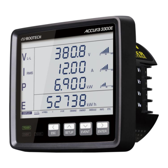
Chapter 3 Operation/Setup Chapter 3 Operation/Setup Front side of Accura 3300E consists of 4.7” LCD which shows measurement data and setup information, three status LEDs which display the state of power supply and communication, and four buttons which select all operation states. -
Page 34: Fig 3.2 Screen Example Of Display Mode
Also at the state that the event is not generated, you can confirm the event logs by long pressing EVENT button. In EVENT Log mode, “Event” segment of top bar is turned on. ⓒ 2015 Rootech Inc. All Rights Reserved Page 34... -
Page 35: Fig 3.4 Screen Example Of Event Log Mode
In SETUP mode, navigation menu on the lower part of LCD changes from the DISPLAY mode to SETUP mode. If a event is generated, RED backlight duration time is default 10 seconds and can be additionally configured up to 999 minutes by the user configuration. ⓒ 2015 Rootech Inc. All Rights Reserved Page 35... - Page 36 Automatically return to DISPLAY mode if there is no button operation for 10 minutes at the SETUP mode. Automatically return to SETUP mode if there is no button operation for 1 minute at the modifying-state. ⓒ 2015 Rootech Inc. All Rights Reserved Page 36...
-
Page 37: Display Mode
Accura 3300E User Guide Chapter 3 Operation/Setup DISPLAY mode Front View Fig 3.5 Accura 3300E Front Overview Voltage Current Active Power Reactive Power Apparent Power Energy Power Factor Line to Neutral Line to Line Total Harmonic Distortion [%] Fundamental FUND... - Page 38 METER Event element configuration EVENT RS-485 communication element configuration COMM Reset element configuration RESET LCD display element configuration DISPLAY Meter information such as serial number, version, etc. INFO Not presently used ⓒ 2015 Rootech Inc. All Rights Reserved Page 38...
-
Page 39: Display Screen
Accura 3300E User Guide Chapter 3 Operation/Setup Display Screen Accura 3300E totally displays measurement parameters. ⓒ 2015 Rootech Inc. All Rights Reserved Page 39... -
Page 40: Measurement Parameter Display Screen
By pressing Up[^] button, the measurement value can be displayed by moving in opposite direction. Fig 3.7 Voltage/Current Display Screen for Each Phase ⓒ 2015 Rootech Inc. All Rights Reserved Page 40... -
Page 41: Fig 3.8 Line To Line Voltage Display Screen
THD and current THD are displayed in order. By pressing Up[v] button, values are displayed in the reverse order. Fig 3.9 Current Display Screen ⓒ 2015 Rootech Inc. All Rights Reserved Page 41... -
Page 42: Fig 3.10 Power Display Screen
By pressing Down[v] button, demand current, maximum demand active power value and maximum demand current are displayed in order. By pressing Up[v] button, values are displayed in the reverse order. Fig 3.11 Demand Active Power Screen ⓒ 2015 Rootech Inc. All Rights Reserved Page 42... -
Page 43: Fig 3.12 Net Energy Display Screen In Energy Display
By pressing Right[>] button again at energy display screen, the screen moves to ETC screen. At ETC screen, the temperature around the device is displayed. Fig 3.13 Temperature Display Screen in ETC Display ⓒ 2015 Rootech Inc. All Rights Reserved Page 43... -
Page 44: Event Log Mode
EVENT Log mode Generation of Event Alarm Accura 3300E provides event alarm if event is detected in case that the event such as fuse fail, phase open, blackout, over temperature, etc. is configured as “on”. When the event alarm is generated, EVENT LED of left-lower part blinks as the LCD backlight turns into red color. -
Page 45: Fig 3.14 Event Log Number Example
E102 E998 E999 Final Event Log number E999 Final Event Log number Event log number is as followed. Event Log number Oldest saved event N-49 Event Log number Latest saved event ⓒ 2015 Rootech Inc. All Rights Reserved Page 45... - Page 46 Display the information when phase open event is generated. Display Event number E[Event] [d][d][d] 000 - 999 Event generated[Phase B B PHSE[Phase] Phase open OPEn[Open] Event generated phase [A, B, C,] is displayed. d decimal. ⓒ 2015 Rootech Inc. All Rights Reserved Page 46...
- Page 47 Over temperature Event Log Display the information when over temperature event is generated. Display Event number E[Event] [d][d][d] 000 - 999 Over temperature event is tEnP [Temperature] generated. OvEr [Over] d decimal ⓒ 2015 Rootech Inc. All Rights Reserved Page 47...
-
Page 48: Setup Mode
Left[<], Up[^], Down[v], Right[>], ESC, and ENTER button. At this time, the position of the present page can be easily confirmed as SETUP menu is displayed on “Navigation Menu” space at lower part of LCD. SETUP Menu ⓒ 2015 Rootech Inc. All Rights Reserved Page 48... -
Page 49: Meter Setup
PT secondary line to line voltage rating Sc[Secondary] [d][d][d] 001 - 999 [default 380] d decimal. Fig 3.15 3 Phase 4 Wire connection: configure “3P4U” and PT primary V , Secondary V ⓒ 2015 Rootech Inc. All Rights Reserved Page 49... -
Page 50: Ab , Secondary
Neutral line is the center point between line1 and line2. Fig 3.18 1P2W connection: configure “1P2U” and PT primary V , Secondary V Line1-Line2 voltage or Line-Neutral voltage connection is possible. ⓒ 2015 Rootech Inc. All Rights Reserved Page 50... -
Page 51: Secondary
Reference current is used as the reference of front bar graph display and TDD configuration. Setting Range CT primary reference current Pr[Primary] [d][d][d][d][d].[d] 00000.1 - 99999.9 [default 50.0] d decimal ⓒ 2015 Rootech Inc. All Rights Reserved Page 51... - Page 52 Demand, noSb Number of Demand Subinterval] Accura 3300E uses “Sliding window” Demand Measuring Method. Demand time[minute] = demand subinterval x number of demand subintervals. Ex] For national case[15 minute demand time], demand subinterval is 15minutes and number of demand subintervals is 1. Refer to chapter 4 for details.
- Page 53 Total VA Calculation Method] Accura 3300E supports two methods for calculation of three phase total power from each phase power. One method is that calculates total apparent power by vector sum of each phase apparent power and the other is that calculates total apparent power by arithmetic sum of each phase apparent power.
- Page 54 The configured minimum measurement value is based on input current of Accura 3300E and current unit is mA. In case of configuring as 20mA[default value] when intput current rating of Accura 3300E is 5A, the value under the 1/250 of the rating would be displayed as 0.
- Page 55 OFF, the sign of reactive power is not displayed. Setting Range Sign of reactive power is displayed. on[ON, default] Sign of reactive power is not displayed. oFF[OFF] ⓒ 2015 Rootech Inc. All Rights Reserved Page 55...
-
Page 56: Event Setup
In case that voltage and current of all phase are measured as 0, it is detected as blackout event. Setting Range Phase open and Blackout event on Phase open and Blackout event off oFF[default] ⓒ 2015 Rootech Inc. All Rights Reserved Page 56... - Page 57 Over temperature event start level 20 - 200 [default 50] Over temperature Event End level[tnP.E Temperature End] Setting Range ℃ 0 to High Level - 1 Over temperature event end level [default 48] ⓒ 2015 Rootech Inc. All Rights Reserved Page 57...
-
Page 58: Rs-485 Communication Setup
Parity Bit[Prty Parity Bit ] Setting Range Even Parity EuEn[default] None Parity nonE Odd Parity Stop Bit[StoP Stop Bit ] Setting Range 1 stop bit 1[default] 2 stop bit ⓒ 2015 Rootech Inc. All Rights Reserved Page 58... - Page 59 Accura 3300E User Guide Chapter 3 Operation/Setup Address[Addr Address: RS-485 Communication Address] Setting Range 1 - 247 [d][d][d] [default 0] d decimal ⓒ 2015 Rootech Inc. All Rights Reserved Page 59...
-
Page 60: Reset Setup
Demand Reset[dMd Demand ] Setting Range Demand reset rESEt[Reset] Maximum/Minimum Reset[MaH Maximum, MIn Minimum ] Demand maximum is reset by the maximum/minimum reset. Setting Range Maximum/minimum reset rESEt[Reset] ⓒ 2015 Rootech Inc. All Rights Reserved Page 60... - Page 61 Accura 3300E User Guide Chapter 3 Operation/Setup Energy Reset[Enrg Energy ] Setting Range Energy[kWh, kVARh, kVAh] reset rESEt[Reset] All Reset[ALL ALL ] Setting Range All [Demand, maximum/minimum, energy] rESEt[Reset] reset ⓒ 2015 Rootech Inc. All Rights Reserved Page 61...
-
Page 62: Display Setup
When event such as dip/swell etc. is generated, LCD backlight turns on as red color for default 5 seconds and remains turn-on state during the configured additional time of event backlight. ⓒ 2015 Rootech Inc. All Rights Reserved Page 62... - Page 63 0°, -120°, 120° of line to line voltage. Unbalance Voltage angles : In case of modifying PT ratio, it provides Provides 0°, -128.4°, 111.6° the proportioned voltage for PT ratio. unbalanced 3 phase ⓒ 2015 Rootech Inc. All Rights Reserved Page 63...
-
Page 64: Compulsory Configuration Step
For normal operation of Accura 3300E, the following compulsory steps should be configured. Accura 3300E Voltage Wiring Connection, PT Rating Configuration Configures voltage wiring connection and PT rating [in case of using external PT] of Accura 3300E. Wiring Connection[Conn Connection] In case of 3 phase 4 wire, the following substeps are skipped as it is default configuration. - Page 65 PT primary [Primary], [Secondary] voltage rating is used as a ratio only for measuring the primary voltage. CT primary [Primary], [Secondary] current rating is used as a ratio only for measuring the primary current. Used as reference value of the bar graph display on the front side. ⓒ 2015 Rootech Inc. All Rights Reserved Page 65...
-
Page 66: Chapter 4 Measurement Description
1 second. As maximum and minimum values after reset provided by Accura 3300E are stored in non volatile memory, even if power supply of Accura 3300E is turned off and then on, these values are preserved. Peak demand is cleared as 0 not by demand reset but by maximum/minimum reset. - Page 67 ▲ ▲ ▲ ▲ Apparent Power Prediction Demand Apparent Power ▲ ▲ Magnitude of Voltage Harmonics Harmonics ▲ (DC, 1 - 31 Magnitude of Current Harmonics ▲ (DC, 1 - 31 ⓒ 2015 Rootech Inc. All Rights Reserved Page 67...
-
Page 68: Measurement Event Parameter
Measurement Event Parameter Measurement event parameters provided by communication and Accura 3300E are shown in the table below. Entering EVENT Log mode, “Event” segment of top bar turns on and event logs up to latest 50 can be confirmed. -
Page 69: Measurement For Voltage Connection
Provided Measurement Values Item Phase voltage [rms] Line-line voltage [rms] Current [rms] Active power Phase A (I1) * PF Phase B (I2) * PF Phase C (I3) * PF Average/ Total ⓒ 2015 Rootech Inc. All Rights Reserved Page 69... -
Page 70: Three Phase 3 Wire Connection
Accura 3300E. And for 3P3W current connection, using 2CT or 3CT are the same in terms of Accura 3300E. By using 3CT rather than 2CT, zero current which is the sum of three currents can be measured. - Page 71 However, by calculating the virtual center point that zero voltage of line to neutral voltage in three phases and considering this as new neutral point, voltage and power for each phase are measured in Accura 3300E. ⓒ 2015 Rootech Inc. All Rights Reserved Page 71...
-
Page 72: Single Phase 3 Wire
= V3 – V1 – V Provided Measurement Values Item Phase voltage [rms] Line-line voltage [rms] Current [rms] Active power (I1) * PF Phase A Phase B (I3) * PF Phase C Average/ Total ⓒ 2015 Rootech Inc. All Rights Reserved Page 72... -
Page 73: Single Phase 2 Wire Connection
= 0 (by 1P2W configuration) = 0 (by 1P2W configuration) Provided Measurement Values Item Phase voltage [rms] Line-line voltage [rms] Current [rms] Active power (I1) * PF Phase A Phase B Phase C Average/ Total ⓒ 2015 Rootech Inc. All Rights Reserved Page 73... -
Page 74: Phase Power Measurement
Chapter 4 Measurement Description Accura 3300E User Guide Phase Power Measurement Accura 3300E supports two methods for calculation of reactive[Q] and apparent power[S]. (1) Fundamental Calculation: Reactive energy is calculated based on fundamental voltage and current. (2) Harmonic Calculation: Reactive energy is calculated based on RMS voltage and current. -
Page 75: Three Phase Total Power Measurement
Chapter 4 Measurement Description Three Phase Total Power Measurement Accura 3300E supports two methods for calculation of reactive [Qt] and apparent power[St] for three phase sum. (1) Vector Sum: Total apparent power is calculated based on vector sum of three phase apparent power. -
Page 76: Arithmetic Sum
The sign of total reactive power follows the sign of total reactive power calculated in vector sum calculation method. = ± √ �� �� − �� �� �� �� Fig 4.7 Vector Diagram for Arithmetic Sum Apparent Power | St | ⓒ 2015 Rootech Inc. All Rights Reserved Page 76... -
Page 77: Power Factor[Pf] Measurement
Note LEAD/LAG of current phase with respect to voltage phase is displayed in the power factor display screen of Accura 3300E. When reactive power is 0, the status is not displayed. ⓒ 2015 Rootech Inc. All Rights Reserved Page 77... -
Page 78: Demand Measurement
Demand Measurement Demand Accura 3300E decides demand time by the product of defined demand subinterval and number of subintervals. Average of demand time is calculated and measured by sliding in demand subinterval half-cycle interval. Peak demand is the maximum value among demands after the reset. -
Page 79: Unbalance[Nema Mg1]
Fig 4.11 Symmetrical Components positive-sequence negative-sequence zero-sequence Zero-sequence component, U0 : Same phase component Positive-sequence component, U1 : Symmetrical component for phase sequence A-B-C Negative-sequence component, U2 : Symmetrical component for phase sequence A-C-B ⓒ 2015 Rootech Inc. All Rights Reserved Page 79... -
Page 80: Negative Sequence Unbalance Ratio
�� Aggregation Accura 3300E provides the basic measurement data corresponding to 0.2 second interval through sensing and processing of voltage and current in every 0.2 second. Aggregation for interval which is longer than 0.2 second, is calculated and provided as the following figure based on the measurement data for 0.2 second. -
Page 81: Appendix A Specification
510g Operating temp -20 to 70C[-4℉ to 158℉] Safety temp -20 to 65C[-4℉ to 149℉] Storage temp -40 to 85C[-40℉ to 185℉] Operating humidity 5% to 95%, non-condensing Conforms to EN61010-1 ⓒ 2015 Rootech Inc. All Rights Reserved Page 81... -
Page 82: Appendix B Standard Compliance
IEC61000-4-5 Surge Immunity IEC61000-4-6 Conducted Radio Frequency Common Mode IEC61000-4-8 Rated Power Frequency Magnetic Field IEC61000-4-11 Voltage Dip/Short Interruptions Certification EN61010-1 EN61326-1, EN61326-2-1 KN22, KN24 ISO 9001:2001[QMS-1347] General Warranty 2 years ⓒ 2015 Rootech Inc. All Rights Reserved Page 82... -
Page 83: Appendix C Accuracy/Reliability
0.0 - 999.9 Class 0.5S means IEC62053-22 Class 0.5S. Class 0.5S means IEC62053-24 Class 0.5S. Class 0.5 means IEC61557-12 Class 0.5. Not displayed on LCD screen of Accura 3300E. It is provided only by communication Power Quality Item Compliance Condition... -
Page 84: Reliability
Conducted Radio Frequency IEC61000-4-6 Common Mode Rated Power Frequency IEC61000-4-8 30A/m 30A/m Magnetic Field half cycle, half cycle, IEC61000-4-11 Voltage Dip each polarity 100% each polarity 100% ⓒ 2015 Rootech Inc. All Rights Reserved Page 84... -
Page 85: Appendix D Ordering Information
Accura 3300E User Guide APPENDIX D Ordering Information APPENDIX D Ordering Information Accura 3300E performs high accuracy measurements of ± 0.2% of reading for voltage and current, conforms to IEC62053-22 class 0.5S for power and energy and provides various power... -
Page 86: Index
INDEX Dimension ............. 19 DISPLAY mode Screen Example ....... 34 Display Screen ..........39 Accura 3300E Digital Power Meter ....15 Display Screen for each phase ......40 Accura 3300E Front Overview ......37 Accura 3300E Mounting ........ 20 Front View ............. 18 Rear View ............ - Page 87 Power Factor Sign .......... 54 Voltage connection ......... 69 Power Display Screen ........42 Voltage Input ..........21 Power Supply/Ground ........31 Voltage Display Screen ........41 PT ..............22 PT Rating............49 ⓒ 2015 Rootech Inc. All Rights Reserved Page 87...
- Page 88 © 2015 Rootech Inc. All Rights Reserved Accura EMeter, Accura 2300S/2350, Accura 2500, Accura 3300E, Accura 3300S/3300, Accura 3700, Accura 3500S/3500, Accura 3550S/3550, Accura 5500, Accura 7500 are trademarks of Rootech Inc. Contact rootech for detailed specifications and order information.
Need help?
Do you have a question about the ACCURA 3300E and is the answer not in the manual?
Questions and answers