Table of Contents
Advertisement
Advertisement
Table of Contents

Related Manuals for Parker Hi-drive


Summary of Contents for Parker Hi-drive
- Page 1 Hi-drive Quick installation guide rev. 0 November 2004 (software rel. 0)
- Page 2 The Hi-drive must be installed in a protected atmosphere. Before using whichever type of drive or motor it is important to analyze to all aspects of the application verifying the characteristics on catalogues currents. The user is the only responsible for the final decision approximately the system and components to use.
-
Page 3: Installation
Parker Hannifin S.p.A. – S.B.C. Division quick installation guide Hi-drive This symbol is an invitation to refer to the more detailed information in the integral version of the operator's manual attached to the supply or which can be downloaded from www.sbcelettronica.com... - Page 4 Parker Hannifin S.p.A. – S.B.C. Division quick installation guide Hi-drive 2.2 Assembly Do not install in hazardous environments. The rear supporting plate features special reamed holes (see illustration). HID2 Type of HID16 HID5 drive HID25 HID8 (width frame) (width plate)
-
Page 5: Wiring Connections
Parker Hannifin S.p.A. – S.B.C. Division quick installation guide Hi-drive WIRING CONNECTIONS • Wire up the panel/drive/motor in accordance with the instructions in the operator's manual and applicable safety regulations. In case of any doubts, contact our After-Sales Service. • Check the correct dimensioning of the drive/motor. Compare the rated voltages and currents. -
Page 6: Connector Layout
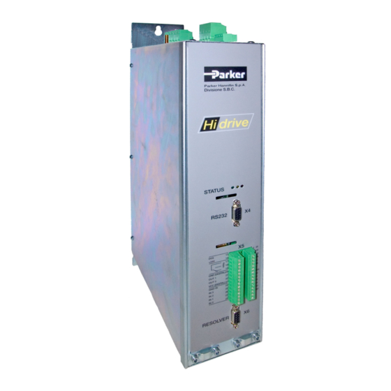
Parker Hannifin S.p.A. – S.B.C. Division quick installation guide Hi-drive 3.3 Connector layout X1 – brake motor mains Top panel drive Status Led (*) otherwise Module Display/Keypad “MOTIONWIZ” on CD-Rom enclosed in stock (optional) Lower panel MAINS Power terminal (top... -
Page 7: Connection To Power Mains
Parker Hannifin S.p.A. – S.B.C. Division quick installation guide Hi-drive X5 : terminal connection 0VQ drive supply – SR drive enabling +24V drive supply + SR drive enabling SC B SC A N.C. GND (DIGITAL) OUT 1 MON 2 OUT 0... - Page 8 Parker Hannifin S.p.A. – S.B.C. Division quick installation guide Hi-drive In the case of D.C. current supply, the maximum voltage must be 744V=. The connection terminals are in terminal board X1 between the terminals RP (positive) and RN (negative). Direct connection to D.C. mains (three-phase) Connection for D.C.
-
Page 9: Encoder Connection
Parker Hannifin S.p.A. – S.B.C. Division quick installation guide Hi-drive FEEDBACK ( FBK ) Types: -FBK A, resolver only (only read if also selected as speed loop feedback). -FBK B, with the Pr62, the following systems can be selected: FBK B... - Page 10 10 FIRST CONVERTER START-UP The drive is supplied from the factory with default programming. Remember that the Hi-drive can control brushless synchronous or asynchronous motors. Before entering the motor data, programme Pr31: write “0” for brushless motor (default condition), “1” for asynchronous motor.
- Page 11 Parker Hannifin S.p.A. – S.B.C. Division quick installation guide Hi-drive Alarms Pr23 Alarm Remedies No alarm Overvoltage Check the three-phase power line. Check the braking line and braking resistance Check the application Undervoltage Check the three-phase power line. Overcurrent Check any mechanical impediments and correct motor size for required use.
- Page 12 MI HI 00 11/04 EN...
Need help?
Do you have a question about the Hi-drive and is the answer not in the manual?
Questions and answers