Table of Contents
Advertisement
Quick Links
I N S T A L L A T I O N I N S T R U C T I O N S
Instrucciones de instalación
Installationsanleitung
Instruções de Instalação
KTC-220
KTC-325
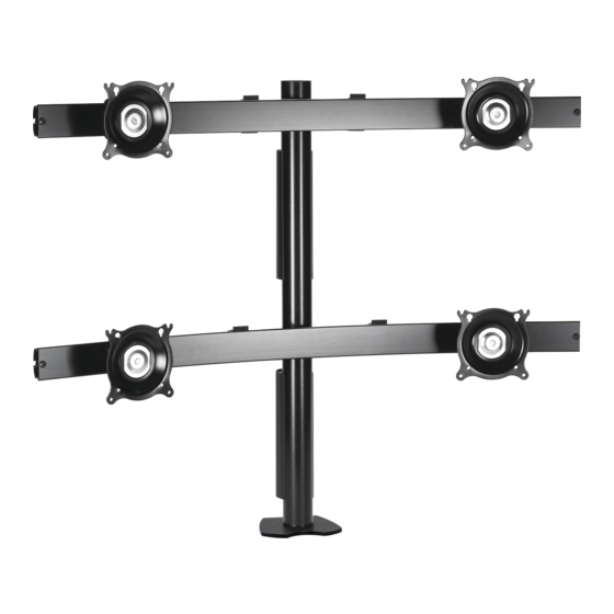
Horizontal and Vertical Desk Clamp Stands
Istruzioni di installazione
Installatie-instructies
Instructions d´installation
KTC-225
KTC-330
KTC-230
KTC-440
Spanish Product Description
German Product Description
Portuguese Product Description
Italian Product Description
Dutch Product Description
French Product Description
KTC SERIES
KTC-320
KTC-445
Advertisement
Table of Contents

Related Manuals for CHIEF KTC Series


Summary of Contents for CHIEF KTC Series
- Page 1 Installatie-instructies Instruções de Instalação Instructions d´installation KTC-225 KTC-220 KTC-320 KTC-230 KTC-325 KTC-330 KTC-440 KTC-445 Horizontal and Vertical Desk Clamp Stands Spanish Product Description German Product Description Portuguese Product Description Italian Product Description Dutch Product Description French Product Description KTC SERIES...
-
Page 2: Installation Instructions
Chief® and Centris™ are registered trademarks of Milestone Reinforce the structure as required before installing the AV Technologies. All rights reserved. - Page 3 Installation Instructions KTC SERIES DIMENSIONS - CONTINUED 17.24 2.25 437.8 3.63 57.2 92.1 6.87 174.6 30.51 774.8 1.96 49.8 1.90 13.25 48.3 336.6 3.75 95.3 .50 [12.7] MIN 3.00 [76.2] MAX 2.75 69.9 KTC-225 3.63 92.1 3.26 82.7 2.25 57.2 5.50...
- Page 4 KTC SERIES Installation Instructions DIMENSIONS - CONTINUED 3.63 92.1 2.25 20.80 57.2 528.3 8.13 206.5 37.14 943.3 1.96 49.8 13.25 1.90 336.6 48.3 3.75 95.3 .50 [12.7] MIN 3.00 [76.2] MAX 2.75 69.9 KTC-320 3.63 92.1 2.25 26.90 57.2 683.4 10.51...
- Page 5 Installation Instructions KTC SERIES DIMENSIONS - CONTINUED 20.80 528.3 3.63 2.25 92.1 57.2 8.13 206.5 37.14 943.3 1.96 49.8 27.25 692.2 1.90 48.3 .50 [12.7] MIN 3.75 2.75 3.00 [76.2] MAX 95.3 69.9 KTC-330 13.68 347.4 3.63 2.25 92.1 57.2 5.88...
- Page 6 KTC SERIES Installation Instructions DIMENSIONS - CONTINUED 17.24 437.8 3.63 2.25 92.1 57.2 6.87 174.6 30.51 774.8 1.96 49.8 27.25 692.2 3.75 95.3 .50 [12.7] MIN 3.00 [76.2] MAX 2.75 KTC-445 69.9...
- Page 7 Installation Instructions KTC SERIES LEGEND Tighten Fastener Pencil Mark Apretar elemento de fijación Marcar con lápiz Befestigungsteil festziehen Stiftmarkierung Apertar fixador Marcar com lápis Serrare il fissaggio Segno a matita Bevestiging vastdraaien Potloodmerkteken Serrez les fixations Marquage au crayon Loosen Fastener Drill Hole Aflojar elemento de fijación...
- Page 8 KTC SERIES Installation Instructions Table 1: Monitor Limits MONITOR LIMITS By MODEL DESCRIPTION Weight 35 lbs 35 lbs 35 lbs 30 lbs 30 lbs. 20 lbs 30 lbs 30 lbs Max Screen Width 22.7" 30" 18" 24.5" 18" 22.7" 30"...
-
Page 9: Tools Required For Installation
Installation Instructions KTC SERIES TOOLS REQUIRED FOR INSTALLATION 5/32" 3/16" 7/32" (included) (included with 230 model only) (included) PARTS (REFER TO TABLE 2 FOR QUANTITIES) 14" 8" 28" 7/32" 3/16" 5/32" 3/4" 3/8" M4 X 30 M4 X 20 M4 X 12... -
Page 10: Installation
KTC SERIES Installation Instructions INSTALLATION Desk Clamp Installation NOTE: In order to reduce the chance of scratching to the mounting surface, bumpers may be installed. However, installation of bumpers is optional. Remove adhesive from underside of bumpers (H). Attach bumpers (H) to underside of desk clamp (D). (See... -
Page 11: Mount Assembly
Installation Instructions KTC SERIES Mount Assembly KTC-220, 225, 320, 325, 330, 440 and 445 Assembly Assemble pole clamp back (M) to pole mount front using KTC-230 Assembly two washers (X) and two 1/4-20 x 3/4" button head cap screws (U) using a 5/32" hex key (J). (See Figure 6) Place front pole clamp with Centris Head (C) against pole (G) in approximate mounting location. - Page 12 KTC SERIES Installation Instructions Attach Centris Head to Recessed Mount Display (P) x 2 NOTE: Refer to Table 1 to select the applicable screw and spacer combination. Uninstall end lock using the 5/32" hex key (J). (See Figure Slide Centris head off array rail. (See Figure 11)
-
Page 13: Display Adjustment
NOTE: Repeat previous steps for each additional display. The KTC Series mount also allows a full 360 deg. of display rotation with a maximum pitch range of 15° up and 15° down. Reinstall end locks into mounting rail using the 5/32" hex key (J) (See Figure 14). -
Page 14: Cable Management
Adjustment Knob Figure 16 CABLE MANAGEMENT The KTC Series mount includes cable management features used to properly route and secure display cables. To use the cable management features: Connect cables to display. Route cables through cable clips on array rail. (See Figure Route cables down pole and away from mount and secure to pole using sheath (E). - Page 15 Installation Instructions KTC SERIES...
- Page 16 Europe A Fellenoord 130 5611 ZB EINDHOVEN, The Netherlands P +31 (0)40 2668620 F +31 (0)40 2668615 Chief Manufacturing, a products division Asia Pacific A Office No. 1 on 12/F, Shatin Galleria of Milestone AV Technologies 18-24 Shan Mei Street...
Need help?
Do you have a question about the KTC Series and is the answer not in the manual?
Questions and answers