Table of Contents
Advertisement
Quick Links
Advertisement
Table of Contents

Related Manuals for MSI MS-9A95 WindBOX IV Advanced


Summary of Contents for MSI MS-9A95 WindBOX IV Advanced
- Page 1 MS-9A95 WindBOX IV Advanced Slim Fanless Box PC...
-
Page 2: Revision History
Preface Copyright and Trademarks Notice Copyright © Micro-Star Int’l Co., Ltd. All rights reserved. The MSI logo used is a registered trademark of Micro-Star Int’l Co., Ltd. All other marks and names mentioned may be trademarks of their respective owners. No warranty as to accuracy or completeness is expressed or implied. -
Page 3: Safety Instructions
MS-9A95 Safety Instructions ■ Always read the safety instructions carefully. ■ Keep this User’s Manual for future reference. ■ Keep this equipment away from humidity. ■ Lay this equipment on a reliable flat surface before setting it up. ■ The openings on the enclosure are for air convection hence protects the equipment from overheating. -
Page 4: Chemical Substances Information
Chemical Substances Information In compliance with chemical substances regulations, such as the EU REACH Regulation (Regulation EC No. 1907/2006 of the European Parliament and the Council), MSI provides the information of chemical substances in products at: https://www.msi.com/html/popup/csr/evmtprtt_pcm.html Battery Information European Union: Batteries, battery packs, and accumulators should not be disposed of as unsorted household waste. -
Page 5: Ce Conformity
MSI will comply with the product take back requirements at the end of life of MSI-branded products that are sold into the EU. -
Page 6: Table Of Contents
Preface CONTENTS Copyright and Trademarks Notice ..............ii Revision History .................... ii Technical Support ..................ii Safety Instructions ..................iii Chemical Substances Information ............... iv Battery Information ..................iv CE Conformity ....................v FCC-A Radio Frequency Interference Statement ......... v WEEE Statement ..................v 1. -
Page 7: Overview
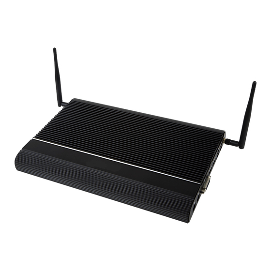
Overview Thank you for choosing the WindBOX IV Advanced, an excellent industrial computer system from MSI. The WindBOX IV Advanced eliminates the noise and the risk of fan’s failure by wide heatsink as fanless solution. Furthermore, it supports VESA wall-mount interface for various scenarios like digital signage, thin... -
Page 8: System Overview
Overview System Overview System I/O & Controls... - Page 9 MS-9A95 Antenna Connector This connector allows you to connect an external antenna for wireless LAN. Users may find one antenna connector on the bottom I/O panel and two on the left and right sides of the system. Line-Out Jack This connector is provided for headphones or speakers. S/PDIF-Out Port S/PDIF (Sony/Philips Digital Interface Format) is a type of digital audio interconnect used in consumer audio equipment, home theaters and other...
- Page 10 Overview RS232 Serial Port The serial port is a 16550A high speed communications port that sends/ receives 16 bytes FIFOs. It supports barcode scanners, barcode printers, bill printers, credit card machine, etc. SIGNAL DESCRIPTION NDCD Data Carrier Detect NSIN Signal In NSOUT Signal Out NDTR...
- Page 11 MS-9A95 HDMI Port (Optional) The High-Definition Multimedia Interface (HDMI) is an all-digital audio/video interface capable of transmitting uncompressed streams. HDMI supports all TV format, including standard, enhanced, or high-definition video, plus multi- channel digital audio on a single cable. DisplayPort (Optional) DisplayPort is a digital display interface standard.
-
Page 12: System Specifications
Overview System Specifications Processor ■ Intel Mobile Skylake/Kaby Lake ULT Core™ i3/i5/i7 Processor ® Memory ■ 2 x 260-pin SO-DIMM slots ■ Support the maximum of 32GB ■ Support Dual Channel for DDR4 2133MHz Network ■ 1 x Intel I219LM GbE LAN PHY ®... - Page 13 MS-9A95 Left Panel Input/Output ■ 1 x Antenna connector ■ 1 x Line-Out jack ■ 1 x S/PDIF-Out port ■ 1 x RS232/422/485 serial port ■ 1 x RS232 serial port ■ 2 x USB 2.0 ports ■ 1 x DC power jack ■...
-
Page 14: Motherboard Jumpers
Overview Motherboard Jumpers JCMOS1 JATX8 JME1 Clear CMOS Jumper: JCMOS1 Normal Clear CMOS (Default) AT/ATX Select Jumper: JATX8 ATX (Default) ME Jumper: JME1 Normal ME disable (Default) -
Page 15: Getting Started
Getting Started This chapter provides you with the information on hardware setup procedures. While doing the installation, be careful in holding the components and follow the installation procedures. For some components, if you install in the wrong orientation, the components will not work properly. -
Page 16: System Cover
Getting Started System Cover system Lay the on a reliable, flat surface before setting it up. Locate the system cover screw and remove it to uncover the system. -
Page 17: Memory
MS-9A95 Memory 1. Locate the SO-DIMM slot. 2. Align the notch on the DIMM with the key on the slot and insert the DIMM into the slot at a 45-degree angle. 3. Push the DIMM gently downwards until the slot levers click and lock the DIMM in place. - Page 18 Getting Started 4. Install more DIMMs if necessary. Important • You can barely see the golden finger if the DIMM is properly inserted in the DIMM slot. • To uninstall the DIMM, flip the slot levers outwards and the DIMM will be released instantly.
-
Page 19: Msata Card (Mini-Pcie 1 Slot)
MS-9A95 mSATA Card (Mini-PCIe 1 Slot) 1. Locate Mini-PCIe slot. Remove the Mini-PCIe card screw preinstalled on the motherboard. 2. Insert the mSATA card into the slot at a 45-degree angle. 3. Push the card gently downwards and fasten it with a screw. -
Page 20: Wifi Card (M.2 E-Key Slot)
Getting Started WiFi Card (M.2 E-Key Slot) 1. Locate the M.2 slot. Remove the M.2 card screw preinstalled on the motherboard. 2. Insert the WiFi card into the slot at a 45-degree angle. 3. Push the card gently downwards and fasten it with a screw. 4. -
Page 21: Wifi Card (Mini-Pcie 2 Slot)
MS-9A95 WiFi Card (Mini-PCIe 2 Slot) 1. Locate Mini-PCIe slot. Remove the Mini-PCIe card screw preinstalled on the motherboard. 2. Insert the WiFi card into the slot at a 45-degree angle. 3. Push the card gently downwards and fasten it with a screw. 4. - Page 22 Getting Started 2.5” HDD/SSD (7mm) 1. Unscrew the HDD bracket and remove it from the system. 2. Available Upon Request: 2 optional screws are available to secure the HDD to the bracket. Before assembly, please make sure the HDD/SSD is compatible with the bracket.
- Page 23 MS-9A95 4. Fasten the HDD bracket to the system with 2 screws.
-
Page 24: Vesa Mount
Getting Started VESA Mount Important Installation 1. Connect your cables to the system. 2. Mount your system onto the VESA mount plate. Removal 1. Dismount your system from the VESA mount plate. 2. Disconnect your cables from the system. Locate the VESA mount screw holes on the back of the monitor. Fasten the VESA mount plate to the monitor with the supplied screws. -
Page 25: Din Rail Mount
MS-9A95 DIN Rail Mount 1. Check the VESA mount plate for the DIN rail screw holes. 2. Put the DIN rails on the VESA mount plate with screw holes aligned. 3. Insert screws through VESA mount plate into the DIN rails and tighten until each DIN rail is secure. -
Page 27: Bios Setup
BIOS Setup This chapter provides information on the BIOS Setup program and allows users to configure the system for optimal use. Users may need to run the Setup program when: ■ An error message appears on the screen at system startup and re- quests users to run SETUP. -
Page 28: Entering Setup
BIOS Setup Entering Setup Power on the computer and the system will start POST (Power On Self Test) process. When the message below appears on the screen, press <DEL> or <F2> key to enter Setup. Press <DEL> or <F2> to enter SETUP If the message disappears before you respond and you still wish to enter Setup, restart the system by turning it OFF and On or pressing the RESET button. - Page 29 MS-9A95 Control Keys ← → Select Screen ↑ ↓ Select Item Enter Select Change Option General Help Previous Values Optimized Defaults Save & Reset Exit Getting Help After entering the Setup menu, the first menu you will see is the Main Menu. Main Menu The main menu lists the setup functions you can make changes to.
-
Page 30: The Menu Bar
BIOS Setup The Menu Bar ▶ Main Use this menu for basic system configurations, such as time, date, etc. ▶ Advanced Use this menu to set up the items of special enhanced features. ▶ Boot Use this menu to specify the priority of boot devices. ▶... -
Page 31: Main
MS-9A95 Main ▶ System Date This setting allows you to set the system date. The date format is <Day>, <Month> <Date> <Year>. ▶ System Time This setting allows you to set the system time. The time format is <Hour> <Minute> <Second>. ▶... -
Page 32: Advanced
BIOS Setup Advanced ▶ Full Screen Logo Display This BIOS feature determines if the BIOS should hide the normal POST messages with the motherboard or system manufacturer’s full-screen logo. When it is enabled, the BIOS will display the full-screen logo during the boot-up sequence, hiding normal POST messages. - Page 33 MS-9A95 ▶ CPU Configuration ▶ Intel Virtualization Technology Virtualization enhanced by Intel Virtualization Technology will allow a platform to run multiple operating systems and applications in independent partitions. With virtualization, one computer system can function as multiple “Virtual” systems. ▶ Active Processor Cores This setting specifies the number of active processor cores.
- Page 34 BIOS Setup ▶ C States C-state performance indicates the ability to run the processor in lower power states when the PC is idle. This setting enables/disables the C-State Configuration for power saving purposes. ▶ Super IO Configuration ▶ Serial Port 1, Serial Port 2 This setting enables/disables the specified serial port.
- Page 35 MS-9A95 ▶ H/W Monitor These items display the current status of all monitored hardware devices/ components such as voltages, temperatures and all fans’ speeds. ▶ Thermal Shutdown This setting enables/disables the thermal shutdown function for system thermal protection.
- Page 36 BIOS Setup ▶ PCI/PCIE Device Configuration ▶ Legacy USB Support Set to [Enabled] if you need to use any USB 1.1/2.0 device in the operating system that does not support or have any USB 1.1/2.0 driver installed, such as DOS and SCO Unix. ▶...
-
Page 37: Boot
MS-9A95 Boot ▶ CSM Support This setting enables/disables the support for Compatibility Support Module, a part of the Intel Platform Innovation Framework for EFI providing the capability to support legacy BIOS interfaces. Important If the Operating System is going to boot in UEFI mode, disable CSM Support to speed up the boot process. -
Page 38: Security
BIOS Setup Security ▶ Administrator Password Administrator Password controls access to the BIOS Setup utility. ▶ User Password User Password controls access to the system at boot and to the BIOS Setup utility. ▶ Intel Trusted Execution Technology Intel Trusted Execution Technology provides highly scalable platform security in physical and virtual infrastructures. - Page 39 MS-9A95 ▶ PCH-FW Configuration ▶ ME State This setting enables/disables ME State. ▶ Manageability Features State This setting enables/disables Manageability Features State. ▶ AMT BIOS Features This setting enables/disables AMT BIOS Feature. ▶ AMT Configuration Intel Active Management Technology (AMT) is hardware-based technology for remotely managing and securing PCs out-of-band.
- Page 40 BIOS Setup ▶ ME Unconfig on RTC Clear This setting enables/disables ME firmware unconfigure on RTC clear. ▶ Comms Hub Support This setting enables/disables Communications Hub Support. ▶ JHI Support This setting enables/disables support for Intel Dynamic Application Loader Host Interface (JHI). ▶...
- Page 41 MS-9A95 ▶ PTT Configuration This menu offers Intel PTT (Platform Trust Technology) Configuration settings. ▶ ME Debug Configuration This menu offers ME Debug settings for testing purposes. 3-15...
- Page 42 BIOS Setup ▶ Trusted Computing ▶ Security Device Support This setting enables/disables BIOS support for security device. When set to [Disable], the OS will not show security device. TCG EFI protocol and INT1A interface will not be available. ▶ SHA-1 PCR Bank, SHA256 PCR Bank These settings enable/disable the SHA-1 PCR Bank and SHA256 PCR Bank.
- Page 43 MS-9A95 ▶ Serial Port Console Redirection ▶ Console Redirection Console Redirection operates in host systems that do not have a monitor and keyboard attached. This setting enables/disables the operation of console redirection. When set to [Enabled], BIOS redirects and sends all contents that should be displayed on the screen to the serial COM port for display on the terminal screen.
- Page 44 BIOS Setup ▶ Terminal Type To operate the system’s console redirection, you need a terminal support- ing ANSI terminal protocol and a RS-232 null modem cable connected be- tween the host system and terminal(s). This setting specifies the type of terminal device for console redirection.
-
Page 45: Chipset
MS-9A95 Chipset ▶ DVMT Pre-Allocated This setting defines the DVMT pre-allocated memory. Pre-allocated memory is the small amount of system memory made available at boot time by the system BIOS for video. Pre-allocated memory is also known as locked memory. This is because it is "locked"... -
Page 46: Power
BIOS Setup Power ▶ Restore AC Power Loss This setting specifies whether your system will reboot after a power failure or interrupt occurs. Available settings are: [Power Off] Leaves the computer in the power off state. [Power On] Leaves the computer in the power on state. [Last State] Restores the system to the previous status before power failure or interrupt occurred. - Page 47 MS-9A95 ▶ PCIE PME This field specifies whether the system will be awakened from power saving modes when activity or input signal of onboard PCIE PME is detected. ▶ RTC When [Enabled], your can set the date and time at which the RTC (real-time clock) alarm awakens the system from suspend mode.
-
Page 48: Save & Exit
BIOS Setup Save & Exit ▶ Save Changes and Reset Save changes to CMOS and reset the system. ▶ Discard Changes and Exit Abandon all changes and exit the Setup Utility. ▶ Discard Changes Abandon all changes. ▶ Load Optimized Defaults Use this menu to load the default values set by the motherboard manufacturer specifically for optimal performance of the motherboard. -
Page 49: Appendix
Appendix This appendix provides the sample codes of WDT (Watch Dog Timer). 2-A-1... -
Page 50: Abstract
Appendix Abstract Abstract In this document, code examples based on C programming language are provided for customer interest. Inportb, Outportb, Inportl and Outportl are basic functions used for access IO ports and defined as following. Inportb: Read a single 8‐bit I/O port. Outportb: Write a single byte to an 8‐bit port. Inportl: Reads a single 32‐bit I/O port. Outportl: Write a single long to a 32‐bit port. ... -
Page 51: Watchdog Timer
MS-9A95 Watchdog Timer 1. Watchdog Timer – WDT The base address (WDT_BASE) of WDT configuration registers is 0xA10. Set WDT Time Unit val = Inportb (WDT_BASE + 0x05); // Read current WDT setting val = val | 0x08; // minute mode. val = val & 0xF7 if second mode Outportb (WDT_BASE + 0x05, val); // Write back WDT setting Set WDT Time Outportb (WDT_BASE + 0x06, Time); // Write WDT time, value 1 to 255. Enable WDT val = Inportb (WDT_BASE + 0x0A); // Read current WDT_PME setting val = val | 0x01; // Enable WDT OUT: WDOUT_EN (bit 0) set to 1. Outportb (WDT_BASE + 0x0A, val); ...
Need help?
Do you have a question about the MS-9A95 WindBOX IV Advanced and is the answer not in the manual?
Questions and answers