Table of Contents
Advertisement
Quick Links
Advertisement
Table of Contents

Related Manuals for MSI MS-S278


Summary of Contents for MSI MS-S278
- Page 1 N1010 Network System User Guide...
-
Page 2: Table Of Contents
Chemical Substances Information................4 Battery ........................... 4 CE Conformity ....................... 5 FCC-A Radio Frequency Interference Statement ............5 System Overview ......................6 MS-S278 ........................6 System Specifications ....................9 Motherboard Connector .................... 10 Motherboard Jumper ....................13 Getting Started ......................14 Necessary Tools .................... -
Page 3: Copyright And Trademarks Notice
Copyright and Trademarks Notice Copyright © Micro-Star Int’l Co., Ltd. All rights reserved. The MSI logo used is a registered trademark of Micro-Star Int’l Co., Ltd. All other marks and names mentioned may be trademarks of their respective owners. No warranty as to accuracy or completeness is expressed or implied. -
Page 4: Weee Statement
Chemical Substances Information In compliance with chemical substances regulations, such as the EU REACH Regulation (Regulation EC No. 1907/2006 of the European Parliament and the Council), MSI provides the information of chemical substances in products at: https://csr.msi.com/global/index Battery Please take special precautions if this product comes with a battery. -
Page 5: Ce Conformity
CE Conformity Hereby, Micro-Star International CO., LTD declares that this device is in compliance with the essential safety requirements and other relevant provisions set out in the European Directive. FCC-A Radio Frequency Interference Statement This equipment has been tested and found to comply with the limits for a Class A digital device, pursuant to Part 15 of the FCC Rules. -
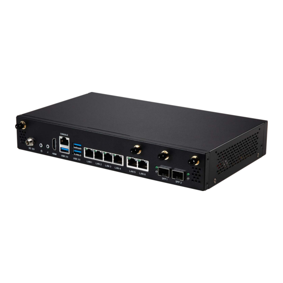
Page 6: System Overview
System Overview MS-S278 2 3 4 System Overview... - Page 7 Power Connector Power supplied through this jack supplies power to your system. System Power Button Press the system power button to turn the system on or off. System Reset Button Press the system reset button to reset the system. HDMI Connector Supports 4K@30Hz as specified in HDMI 1.4b.
- Page 8 RJ45 Serial Console Port Network routers and switches typically require an RS-232 serial data connection to interface with the system for initial configuration. Serial data connections may also be used for diagnostics purposes, especially when a network device is malfunctioning and unreachable over the network. Connect a specially configured RJ45 console cable to this jack for network routers/switches to communicate with the system through a serial connection.
-
Page 9: System Specifications
System Specifications Model MS-S278 Model Number N1010 Processor Intel® Atom™ Elkhart Lake, 4C4T, 2.0GHz, 10nm Cipset Nuvoton NCT6126D Memory 2 x SO-DIMM slots, DDR4 non-ECC, up to 16GB ∙ 1 x M.2 M-key 2242/ 2280 (SATA/ PCIe) Storage ∙ 1 x Internal 2.5” SSD (SATA 3.0) ∙... -
Page 10: Motherboard Connector
Motherboard Connector JPWR1: ATX 4-pin Power Connector JHDDPWR1: HDD Power Connector JSDOMPWR1, JSDOMPWR2: SATA DOM Power Connector CPU_FAN1, SYS_FAN1: Fan Power Connector JCI1: Chassis Intrusion Header JPWR1 JHDDPWR1 P12V P12V CPU_FAN1 JSDOMPWR1 SYS_FAN1 FAN POWER FAN SENSE FAN_PWM JCI1 FM_INTRUDER_HDR_N Normal Trigger the chassis (default) - Page 11 JCOM1: COM Port JUSB1: USB 2.0 Box Header JGPIO1: GPIO Header JRST1: Reset Header JCOM1 JUSB1 No pin No pin SOUT JGPIO1 JRST1 Reset No pin SIO_GP46 SIO_GP35 SIO_GP43 SIO_GP34 SIO_GP41 SIO_GP06 SIO_GP36 SIO_GP02 Motherboard Connector...
- Page 12 JTPM1: TPM Module Box Header USIM1: Nano SIM Holder JTPM1 SPI_CS0#_R No pin RST_RSMRST_N P3V3_P1V8_PCH_SPI_AUX SPI_PCH_IO2 SPI_CLK_R SPI_MISO_R SPI_PCH_IO3 SPI_MOSI_R SPI_PCH_TPM_DEDIPROG_CS_N P3V3_P1V8_PCH_SPI_AUX P3V3_P1V8_PCH_SPI_AUX IRQ_TPM_SPI_N P3V3_P1V8_PCH_SPI_AUX RST_PLTRST_B_N USIM1 Motherboard Connector...
-
Page 13: Motherboard Jumper
Motherboard Jumper Jumper Name Default Setting Description 1-2: Using 3.81V J5K1 2-3: Using 3.3V (default) Motherboard Jumper... -
Page 14: Getting Started
Getting Started ⚠ Important All information is subject to change without prior notice. Necessary Tools Tools Descriptions A Phillips (crosshead) screwdriver and a flathead screwdriver can be used to do most of the installation. Choose one with a magnetic head would be better. Pliers can be used as an auxiliary tool to connect some connectors or cables. -
Page 15: Safety Precautions
Safety Precautions The following precautions should be observed while handling the system: ∙ Place the system on a flat and stable surface. ∙ Do not place the system in environments subject to mist, smoke, vibration, excessive dust, salty or greasy air, or other corrosive gases and fumes. ∙... -
Page 16: System Setup
System Setup ⚠ Important Before removing or installing any components, make sure the system is not turned ∙ on or connected to the power. Memory 1. Unlock the DIMM slot by flipping open its side clips. 2. Vertically insert the DIMM into the DIMM slot. The DIMM has an off-center notch at the bottom that will only allow it to fit one way into the DIMM slot. -
Page 17: Recommended Memory Population
Recommended Memory Population Quantity of DIMMs SOCKET2 SOCKET1 SOCKET1 SOCKET2 **“V” indicates a populated DIMM slot. ** ⚠ Important ∙ There should be at least one DDR4 DIMM per socket. ∙ Paired memory installation for Max performance. ∙ If only one DIMM is populated in a channel, then populate it in the slot furthest away from CPU of that channel. -
Page 18: Sata Disk On Module (Optional)
SATA Disk on Module (Optional) 1. Locate the SATA DOM port on the motherboard. 2. Connect the SATA DOM to the port. SATA Disk on Module (Optional) -
Page 19: Slot (Optional)
M.2 Slot (Optional) CON1: E Key (PCIe 3.0 x1, 2230) CON2: B Key (3042/ 3052) 1. Loosen the M.2 riser screw from the motherboard. 2. Move and fasten the M.2 riser screw to the appropriate location according your M.2 SSD size. -
Page 20: Con3: M Key (Pcie 3.0 X1, 2242/ 2280)
CON3: M Key (PCIe 3.0 x1, 2242/ 2280) 1. Loosen the M.2 riser screw from the motherboard. 2. Move and fasten the M.2 riser screw to the appropriate location according your M.2 SSD size. 3. Insert your M.2 SSD into the M.2 slot at a 30°... -
Page 21: Hard Disk Drive (Optional)
Hard Disk Drive (Optional) 1. Locate the HDD bracket in the system and remove the screws fixing it. Release the HDD bracket from the system for installation. 2. Fit the HDD into the bracket with screw holes aligned. Fasten the screws to secure the HDD to the bracket. - Page 22 4. Connect the HDD power and signal cable to the motherboard. 5. Place and secure the HDD set back to the system. Hard Disk Drive (Optional)
Need help?
Do you have a question about the MS-S278 and is the answer not in the manual?
Questions and answers