Table of Contents
Advertisement
Quick Links
Advertisement
Table of Contents

Related Manuals for MSI 919-98H2-001


Summary of Contents for MSI 919-98H2-001
- Page 1 MS-98H2 Qseven R 2.0 CPU Module Board...
-
Page 2: Revision History
Alterna- tively, please try the following help resources for further guidance. Visit the MSI website for technical guide, BIOS updates, driver updates and other information, or contact our technical staff via http://www.msi.com/support/... -
Page 3: Safety Instructions
MS-98H2 Safety Instructions ■ Always read the safety instructions carefully. ■ Keep this User’s Manual for future reference. ■ Keep this equipment away from humidity. ■ Lay this equipment on a reliable flat surface before setting it up. ■ The openings on the enclosure are for air convection hence protects the equipment from overheating. -
Page 4: Chemical Substances Information
Chemical Substances Information In compliance with chemical substances regulations, such as the EU REACH Regulation (Regulation EC No. 1907/2006 of the European Parliament and the Council), MSI provides the information of chemical substances in products at: http://www.msi.com/html/popup/csr/evmtprtt_pcm.html Battery Information European Union: Batteries, battery packs, and accumulators should not be disposed of as unsorted household waste. -
Page 5: Ce Conformity
MSI will comply with the product take back requirements at the end of life of MSI-branded products that are sold into the EU. -
Page 6: Japan Jis C 0950 Material Declaration
Declaration A Japanese regulatory requirement, defined by specification JIS C 0950, man- dates that manufacturers provide material declarations for certain categories of electronic products offered for sale after July 1, 2006. http://www.msi.com/html/popup/csr/cemm_jp.html http://tw.msi.com/html/popup/csr_tw/cemm_jp.html 日本JIS C 0950材質宣言 日本工業規格JIS C 0950により、2006年7月1日以降に販売される特定分野の 電気および電子機器について、製造者による含有物質の表示が義務付けられま... -
Page 7: Vietnam Rohs
Việt Nam RoHS Kể từ ngày 01/12/2012, tất cả các sản phẩm do công ty MSI sản xuất tuân thủ Thông tư số 30/2011/TT-BCT quy định tạm thời về giới hạn hàm lượng cho phép... -
Page 8: Table Of Contents
Preface Contents Copyright Notice .................... ii Trademarks ....................ii Revision History .................... ii Technical Support ..................ii Safety Instructions ..................iii Chemical Substances Information ............... iv Battery Information ..................iv CE Conformity ....................v FCC-A Radio Frequency Interference Statement ......... v WEEE Statement .................. -
Page 9: Overview
Overview Thank you for choosing the MS-98H2, an excellent Qseven R 2.0 CPU Module Board. Integrating core CPU and memory functionality, it is the entry-level model for applications looking to transition from other small form factor solutions to Qseven and offers full PCI Express, USB, SATA, audio, graphics and network support. -
Page 10: Board Specifications
Overview Board Specifications Processor (Optional) ■ Intel Pentium Processor N3710 (QC/1.6GHz/2.56GHz for Burst/TDP-6W) ® ® ■ Intel Celeron Processor N3160 (QC/1.6GHz/2.24GHz for Burst/TDP-6W) ® ® Memory ■ Onboard DDR3L 1600 MHz memory modules ■ Supports the maximum of 4 GB ■... - Page 11 MS-98H2 Power ■ +5 V and +5 VSB (standby power) Environmental ■ Operating Temperature: -10 ~ 60 C (Constrain: Heatspreader for 0~40°C ) ■ Storage Temperature: -20 ~ 80 ■ Humidity: 10 ~ 90% RH, non-condensing Regulatory Compliance ■ EMC: CE, FCC, BSMI, RCM, VCCI ■...
-
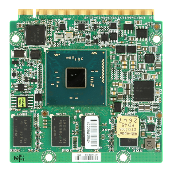
Page 12: Board Layout
Overview Board Layout Memory Edge Fingers... -
Page 13: Block Diagram
MS-98H2 Block Diagram... -
Page 15: Hardware Setup
Hardware Setup This chapter provides you with the information about hardware setup procedures. While doing the installation, be careful in holding the components and follow the installation procedures. For some components, if you install in the wrong orientation, the components will not work properly. -
Page 16: Edge Fingers
Hardware Setup Edge Fingers On the top and bottom side of the Qseven Module Board are 115 edge fingers that mate with the MXM connector. The following table lists the pin assignments for all 230 edge fingers. - Page 17 Connector Pin Assignments MS-98H2 ® There are 115 edge fingers on the top and bottom side of the Qseven module that mate with the MXM connector. Table 3-1 lists the pin assignments for all 230 edge fingers. Table 3-1 Connector Pinout Description Signal Signal GBE_MDI3-...
- Page 18 Hardware Setup ® Qseven Specification 2.0 Signal Signal THRM# WDTRIG# THRMTRIP# USB_P7- / USB_SSTX0- USB_P6- / USB_SSRX0- USB_P7+ / USB_SSTX0+ USB_P6+ / USB_SSRX0+ USB_P5- / USB_SSTX1- USB_P4- / USB_SSRX1- USB_P5+ / USB_SSTX1+ USB_P4+ / USB_SSRX1+ USB_2_3_OC# USB_0_1_OC# USB_P3- USB_P2- USB_P3+ USB_P2+ USB_ID USB_P1-...
- Page 19 MS-98H2 ® Qseven Specification 2.0 Signal Signal DP_LANE0+ / TMDS_LANE2+ HDMI_CTRL_DAT DP_LANE0- / TMDS_LANE2- HDMI_CTRL_CLK DP_HDMI_HPD# RSVD PCIE_CLK_REF+ PCIE_WAKE# PCIE_CLK_REF- PCIE_RST# PCIE2_TX+ PCIE2_RX+ PCIE2_TX- PCIE2_RX- UART0_TX UART0_RTS# PCIE1_TX+ PCIE1_RX+ PCIE1_TX- PCIE1_RX- UART0_RX UART0_CTS# PCIE0_TX+ PCIE0_RX+ PCIE0_TX- PCIE0_RX- LPC_AD0 / GPIO0 LPC_AD1 / GPIO1 LPC_AD2 / GPIO2 LPC_AD3 / GPIO3...
-
Page 20: Hardware Installation
Hardware Setup Hardware Installation h Installing Module Board onto Carrier Board Important The illustrations are provided to guide users on how to install the module board onto the carrier board of their choice and should be held for reference only. 1. - Page 21 MS-98H2 3. Locate the thermal pad on the heat spreader. Peel off the protective film of the thermal pad. 4. Mount the heat spreader onto the module board with mounting holes aligned. Use the provided mounting screws to secure the heat spreader to the module board and the carrier board.
-
Page 23: Bios Setup
BIOS Setup This chapter provides information on the BIOS Setup program and allows users to configure the system for optimal use. Users may need to run the Setup program when: ■ An error message appears on the screen at system startup and re- quests users to run SETUP. -
Page 24: Entering Setup
BIOS Setup Entering Setup Power on the computer and the system will start POST (Power On Self Test) process. When the message below appears on the screen, press <DEL> or <F2> key to enter Setup. Press <DEL> or <F2> to enter SETUP If the message disappears before you respond and you still wish to enter Setup, restart the system by turning it OFF and On or pressing the RESET button. - Page 25 MS-98H2 Control Keys ← → Select Screen ↑ ↓ Select Item Enter Select Change Option General Help Previous Values Optimized Defaults Save & Exit Exit Getting Help After entering the Setup menu, the first menu you will see is the Main Menu. Main Menu The main menu lists the setup functions you can make changes to.
-
Page 26: The Menu Bar
BIOS Setup The Menu Bar ▶ Main Use this menu for basic system configurations, such as time, date, etc. ▶ Advanced Use this menu to set up the items of special enhanced features. ▶ Boot Use this menu to specify the priority of boot devices. ▶... -
Page 27: Main
MS-98H2 Main ▶ System Date This setting allows you to set the system date. The date format is <Day>, <Month> <Date> <Year>. ▶ System Time This setting allows you to set the system time. The time format is <Hour> <Min- ute>... -
Page 28: Advanced
BIOS Setup Advanced ▶ Full Screen Logo Display This BIOS feature determines if the BIOS should hide the normal POST mes- sages with the motherboard or system manufacturer’s full-screen logo. When it is enabled, the BIOS will display the full-screen logo during the boot-up sequence, hiding normal POST messages. - Page 29 MS-98H2 ▶ Super IO Configuration ▶ Serial Port 1/ 2/ 3/ 4/ 5/ 6 This setting enables/disables the specified serial port. ▶ Change Settings This setting is used to change the address & IRQ settings of the specified serial port. ▶...
- Page 30 BIOS Setup ▶ H/W Monitor These items display the current status of all monitored hardware devices/ components such as voltages, temperatures and all fans’ speeds. ▶ Smart Fan Configuration ▶ Smart CPUFAN/SYSFAN Target These setting enables/disables the Smart Fan function. Smart Fan is an excellent feature which will adjust the CPU/system fan speed automatically depending on the current CPU/system temperature, avoiding the overheating to damage your system.
- Page 31 MS-98H2 ▶ CPU Configuration ▶ Intel Virtualization Technology Virtualization enhanced by Intel Virtualization Technology will allow a platform to run multiple operating systems and applications in independent partitions. With virtualization, one computer system can function as multiple “Virtual” systems. ▶ PCI/PCIE Device Configuration ▶...
- Page 32 BIOS Setup takes over. When set to higher values, every PCI device can conduct transactions for a longer time and thus improve the effective PCI bandwidth. For better PCI performance, you should set the item to higher values. ▶ Legacy USB Support Set to [Enabled] if you need to use any USB 1.1/2.0 device in the operating system that does not support or have any USB 1.1/2.0 driver installed, such as DOS and SCO Unix.
-
Page 33: Boot
MS-98H2 Boot ▶ CSM Support This setting enables/disables the support for Compatibility Support Module, a part of the Intel Platform Innovation Framework for EFI providing the capability to support legacy BIOS interfaces. ▶ Video This setting selects the video mode. ▶... -
Page 34: Security
BIOS Setup Security ▶ Administrator Password Administrator Password controls access to the BIOS Setup utility. ▶ User Password User Password controls access to the system at boot and to the BIOS Setup utility. ▶ Chassis Intrusion The field enables or disables the feature of recording the chassis intrusion status and issuing a warning message if the chassis is once opened. - Page 35 MS-98H2 ▶ Trusted Computing ▶ Security Device Support This setting enables/disables BIOS support for security device. When set to [Disable], the OS will not show security device. TCG EFI protocol and INT1A interface will not be available. ▶ Serial Port Console Redirection ▶...
- Page 36 BIOS Setup should be displayed on the screen to the serial COM port for display on the terminal screen. Besides, all data received from the serial port is interpreted as keystrokes from a local keyboard. ▶ Console Redirection Settings ▶ Terminal Type To operate the system’s console redirection, you need a terminal support- ing ANSI terminal protocol and a RS-232 null modem cable connected be- tween the host system and terminal(s).
- Page 37 MS-98H2 ▶ Putty Keypad PuTTY is a terminal emulator for Windows. This setting controls the numer- ic keypad for use in PuTTY. ▶ Redirection After BIOS POST This setting determines whether or not to keep terminals’ console redirection running after the BIOS POST has booted. ▶...
-
Page 38: Chipset
BIOS Setup Chipset ▶ DVMT Pre-Allocated This setting defines the DVMT pre-allocated memory. Pre-allocated memory is the small amount of system memory made available at boot time by the system BIOS for video. Pre-allocated memory is also known as locked memory. This is because it is "locked"... -
Page 39: Power
MS-98H2 Power ▶ Restore AC Power Loss This setting specifies whether your system will reboot after a power failure or interrupt occurs. Available settings are: [Power Off] Leaves the computer in the power off state. [Power On] Leaves the computer in the power on state. [Last State] Restores the system to the previous status before power failure or interrupt occurred. - Page 40 BIOS Setup ▶ USB from S3/S4 The item allows the activity of the USB device to wake up the system from S3/ S4 sleep state. ▶ RTC When [Enabled], your can set the date and time at which the RTC (real-time clock) alarm awakens the system from suspend mode.
-
Page 41: Save & Exit
MS-98H2 Save & Exit ▶ Save Changes and Reset Save changes to CMOS and reset the system. ▶ Discard Changes and Exit Abandon all changes and exit the Setup Utility. ▶ Discard Changes Abandon all changes. ▶ Load Optimized Defaults Use this menu to load the default values set by the motherboard manufacturer specifically for optimal performance of the motherboard.
Need help?
Do you have a question about the 919-98H2-001 and is the answer not in the manual?
Questions and answers