Table of Contents
Advertisement
Advertisement
Table of Contents

Related Manuals for MSI MS-9856


Summary of Contents for MSI MS-9856
- Page 1 MS-9856 Industrial Computer Board...
-
Page 2: Copyright Notice
If a problem arises with your system and no solution can be obtained from the user’s manual, please contact your place of purchase or local distributor. Alternatively, please try the following help resources for further guidance. ◙ Visit the MSI website for FAQ, technical guide, BIOS updates, driver updates, and other information: http://www.msi.com/index. php?func=service ◙... -
Page 3: Safety Instructions
MS-9856 Safety Instructions ■ Always read the safety instructions carefully. ■ Keep this User’s Manual for future reference. ■ Keep this equipment away from humidity. ■ Lay this equipment on a reliable flat surface before setting it up. ■ The openings on the enclosure are for air convection hence protects the equipment from overheating. -
Page 4: Fcc-B Radio Frequency Interference Statement
Shielded interface cables and AC power cord, if any, must be used in order to com- ply with the emission limits. Micro-Star International MS-9856 OIR LA NOTICE D’INSTALLATION AVANT DE RACCORDER AU RESEAU. This device complies with Part 15 of the FCC Rules. Operation is subject to the... -
Page 5: August
MSI will comply with the product take back requirements at the end of life of MSI-branded products that are sold into the EU. - Page 6 MSI će poštovati zahtev o preuzimanju ovakvih proizvoda kojima je istekao vek trajanja, koji imaju MSI oznaku i koji su prodati u EU. Ove proizvode možete vratiti na lokalnim mestima za prikupljanje.
- Page 7 MSI si adeguerà a tale Direttiva ritirando tutti i prodotti marchiati MSI che sono stati venduti all’interno dell’Unione Europea alla fine del loro ciclo di vita.
-
Page 8: Table Of Contents
▍ PREFACE ▍ TABLE OF CONTENTS Copyright Notice �������������������������������������������������������������������������������������������������� ii Trademarks ���������������������������������������������������������������������������������������������������������� ii Revision History �������������������������������������������������������������������������������������������������� ii Technical Support ����������������������������������������������������������������������������������������������� ii Safety Instructions ��������������������������������������������������������������������������������������������� iii FCC-B Radio Frequency Interference Statement �������������������������������������������� iv WEEE (Waste Electrical and Electronic Equipment) Statement ��������������������� v Chapter 1 Overview ������������������������������������������������������������������������������������������... - Page 9 MS-9856 Chapter 4 System Resources ��������������������������������������������������������������������� 4-1 Watch Dog Timer Setting ..............4-2 AMI POST Code ................... 4-3 Resource List ..................4-7...
-
Page 11: Chapter 1 Overview
Chapter 1 Overview Thank you for choosing the MS-9856 v1.X, an excel- lent industrial computer board from MSI. Based on the innovative Intel 945GSE & ICH7M ® chipsets for optimal system efficiency, the MS-9856 accommodates the latest Intel ATOM N270 processor ®... -
Page 12: Mainboard Specifications
▍ OVERVIEW ainboard pecificationS Processor ■ Intel ATOM N270 low power processor ■ 533/ 400 MHz Chipset ■ North Bridge: Intel 945GSE chipset ■ South Bridge: Intel ICH7M chipset Memory ■ 1 DDR2 533/400 SO-DIMM slot (200 pins / 1.8V) ■... -
Page 13: Form Factor
MS-9856 ■ Onboard Connectors/Pinheaders 1 front audio pinheader 1 USB 2.0 pinheader (2 ports) 1 SPI Flash ROM pinheader (for debugging) 4 serial port pinheaders 4 In/ 4 Out GPIO pinheaders 1 LVDS connector 1 keyboard/mouse pinheader Slot ■ 1 Mini PCI-E slot Form Factor ■... -
Page 14: Block Diagram
▍ OVERVIEW lock iagraM... -
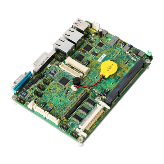
Page 15: Mainboard Layout
MS-9856 ainboard ayout MS-9856 v1.X Mainboard... -
Page 16: Board Dimension
▍ OVERVIEW oard iMenSion... -
Page 17: Safety Compliance & Mtbf
MS-9856 & Mtbf afety oMpliance Certification Standard number Title of standard EN 55022: 1998+A1: Product family 2000+A2:2003 Class B standard EN 6100-3-2:2000 Limits for harmonic Class D current emission EN 6100-3-3: Limitation of voltage 1995+A1:2001 fluctuation and flicker in low voltage supply... -
Page 19: Chapter 2 Hardware Setup
Chapter 2 Hardware Setup This chapter provides you with the information on mainboard hardware configurations. Incorrect setting of jumpers and connectors may damage your main- board. Please pay special attention not to connect these headers in wrong direction. DO NOT adjust any jumper while the mainboard is powered on. -
Page 20: Hardware Setup
▍ Hardware Setup uick omponents uide SO-dIMM Slot, p.2-3 pwr1, p.2-4 CON1, p.2-15 JBat1, p.2-13 Back panel I/O, p.2-5 JVdd1, p.2-14 JLVdS1, p.2-11 JCOMp1, p.2-13 JuSB1, p.2-12 J3, p.2-9 JFp1, p.2-9 Jaud1, p.2-10 Sata1~2, p.2-6 JSpI1, p.2-7 JKBMS1, p.2-7 Jpwr1, p.2-4 J2, p.2-8... -
Page 21: Memory
MS-9856 emory These DIMM slots are intended for memory modules. ddr2 SO-dIMM Slot 200-pin, 1.8V Installing Memory Modules Locate the DIMM1 SO-DIMM slot. Align the notch on the DIMM with the key on the slot and insert the DIMM into the slot at 45-degree angle. -
Page 22: Power Supply
▍ Hardware Setup ower upply 5V/12V Hdd power Connector: Jpwr1 This connector provides power to the hard disk drives. SIGNaL VCC5 +12V Jpwr1 12V System power Connector: pwr1 This connector provides power to the system. SIGNaL +12V +12V pwr1 Important Power supply of 200watts (and above) is highly recommended for system stability. -
Page 23: Back Panel I/O
MS-9856 anel uSB port Serial port dVI-I port ▶ uSB port The USB (Universal Serial Bus) port is for attaching USB devices such as keyboard, mouse, or other USB-compatible devices. ▶ The standard RJ-45 LAN jack is for connec- Activity Indicator Speed Indicator tion to the Local Area Network (LAN). -
Page 24: Connectors
▍ Hardware Setup onnectors Serial ata II Connector: Sata1, Sata2 This connector is a high-speed Serial ATA II interface port. Each connector can connect to one Serial ATA II device. Sata2 Sata1 Important Please do not fold the Serial ATA cable into 90-degree angle. Otherwise, data loss may occur during transmission. - Page 25 MS-9856 SpI Flash rOM Connector: JSpI1 This connector is used to flash SPI flash ROM. JSpI1 SIGNaL SIGNaL VCC3_SB VCC3_SB SPI_MISO_F SPI_MOSI_F SPI_CS0_F# SPI_CLK_F SPI_HOLD# Keyboard/Mouse Connector: JKBMS1 This connector is used to connect PS/2 keyboard & mouse. JKBMS1 SIGNaL...
- Page 26 ▍ Hardware Setup Serial port Connector: J2 This connector is a 16550A high speed communications port that sends/re- ceives 16 bytes FIFOs. You can attach serial devices to it through the optional serial port bracket. SIGNaL SIGNaL COM_NDCD2 COM_NDCD4 COM_NRD2 COM_NRD4 COM_NTD2 COM_NTD4...
- Page 27 MS-9856 digital IO Connector: J3 This connector is provided for the General-Purpose Input/Output (GPIO) pe- ripheral module. SIGNaL SIGNaL VCC5 N_GPO 3 N_GPO 1 N_GPO 2 N_GPO 0 N_GPI 3 N_GPI 1 N_GPI 2 N_GPI 0 Front panel Connector: JFp1 This front panel connector is provided for electrical connection to the front panel switches &...
- Page 28 ▍ Hardware Setup Front panel audio Connector: Jaud1 This connector allows you to connect the front panel audio and is compliant with Intel Front Panel I/O Connectivity Design Guide. Jaud1 SIGNaL deSCrIptION MIC_L Microphone - Left channel Ground MIC_R Microphone - Right channel PRESENCE# Active low signal-signals BIOS that a High Definition Audio dongle is connected to the analog header.
- Page 29 MS-9856 LVdS Flat panel Connector: JLVdS1 The LVDS (Low Voltage Differential Signal) connector provides a digital interface typically used with flat panels. After connecting an LVDS interfaced flat panel to the JLVDS1, be sure to check the panel datasheet and set the JVDD1 jumper (p.
- Page 30 ▍ Hardware Setup Front uSB Connector: JuSB1 This connector, compliant with Intel I/O Connectivity Design Guide, is ideal for con- necting high-speed USB interface peripherals such as USB HDD, digital cameras, MP3 players, printers, modems and the like. SIGNaL SIGNaL JuSB1 USB_RSTR SBD1+...
-
Page 31: Jumpers
MS-9856 umpers COM port power Jumper: JCOMp1 These jumpers specify the operation voltage of the onboard serial ports. VCC5 +12V VCC5 +12V JCOMp1 Clear CMOS Jumper: JBat1 There is a CMOS RAM onboard that has a power supply from an external battery to keep the data of system configuration. - Page 32 ▍ Hardware Setup Backlight Connector & LVdS power Jumper: JVdd1 The backlight connector is provided for LCD backlight options while the LVDS power jumper allows users to select the operation voltage of the LVDS inter- faced flat panel. SIGNaL JVdd1 LVDS Power Jumper VCC5 L_BKLTCTL...
-
Page 33: Slot
MS-9856 pCI (peripheral Component Interconnect) express Slot The PCI Express slot supports the PCI Express interface expansion card. The CON1 is a Mini PCI-E connector for wireless LAN, TV tuner, and Robson NAND Flash . Mini pCI-e Slot Important When adding or removing expansion cards, make sure that you unplug the power supply first. -
Page 35: Chapter 3 Bios Setup
Chapter 3 BIOS Setup This chapter provides information on the BIOS Setup program and allows you to configure the system for optimum use. You may need to run the Setup program when: ■ An error message appears on the screen during the system booting up, and requests you to run SETUP. -
Page 36: Entering Setup
▍ BIOS SETUP ntering etup Power on the computer and the system will start POST (Power On Self Test) pro- cess. When the message below appears on the screen, press <DEL> key to enter Setup. Press DEL to enter SETUP If the message disappears before you respond and you still wish to enter Setup, restart the system by turning it OFF and On or pressing the RESET button. -
Page 37: Control Keys
MS-9856 Control Keys <↑> Move to the previous item <↓> Move to the next item <←> Move to the item in the left hand <→> Move to the item in the right hand <Enter> Select the item <Esc> Jumps to the Exit menu or returns to the main menu from a sub- menu <+/PU>... -
Page 38: The Menu Bar
▍ BIOS SETUP ▶ Main Use this menu for basic system configurations, such as time, date etc. ▶ Advanced Use this menu to setup the items of special enhanced features. ▶ Boot Use this menu to specify the priority of boot devices. ▶... -
Page 39: Main
MS-9856 ▶ System Time This setting allows you to set the system time. The time format is <Hour> <Minute> <Second>. ▶ System Date This setting allows you to set the system date. The date format is <Day>, <Month> <Date> <Year>. - Page 40 ▍ BIOS SETUP [Block Any selection except Disabled determines the (Multi-Sector number of sectors transferred per block Transfer)] [PIO Mode] Indicates the type of PIO (Programmed Input/Output) [DMA Mode] Indicates the type of Ultra DMA [S.M.A.R.T.] This allows you to activate the S.M.A.R.T. (Self-Monitoring Analysis &...
-
Page 41: Advanced
MS-9856 dvanced ▶ CPU Configuration... - Page 42 ▍ BIOS SETUP ▶ Max CPUID Value Limit The Max CPUID Value Limit BIOS feature allows you to circumvent prob- lems with older operating systems that do not support the Intel Pentium 4 processor with Hyper-Threading Technology. When enabled, the processor will limit the maximum CPUID input value to 03h when queried, even if the processor supports a higher CPUID input value.
- Page 43 MS-9856 ▶ PCI/PCIE Device Configuration ▶ USB Functions This setting specifies the operation mode of the onboard USB control- ler. ▶ USB 2�0 Controller This setting enables/disables the onboard USB controller. ▶ Audio Controller This setting enables/disables the onboard audio controller.
- Page 44 ▍ BIOS SETUP ▶ Super IO Configuration ▶ Serial Port 1/2/3/4/5/6 Address, Serial Port 3/4/5 IRQ Select an address and a corresponding interrupt for the specified serial ports. ▶ Serial Port 3/4/5 Mode These settings specify the operation mode of the specified serial ports. ▶...
- Page 45 MS-9856 ▶ Hardware Health Configuration These items display the current status of all monitored hardware devices/ components such as voltages, temperatures and all fans’ speeds. 3-11...
- Page 46 ▍ BIOS SETUP ▶ GPIO Configuration ▶ GP 60/ 61/ 62/ 63/ 64/ 65/ 66/ 67 Data These settings configure special GPIO data. 3-12...
-
Page 47: Boot
MS-9856 ▶ 1st/2nd/3rd Boot Device The items allow you to set the sequence of boot devices where BIOS at- tempts to load the disk operating system. ▶ Try Other Boot Devices Setting the option to [Enabled] allows the system to try to boot from other device if the system fails to boot from the 1st/2nd/3rd boot device. -
Page 48: Security
▍ BIOS SETUP ecurity ▶ Supervisor Password / Change Supervisor Password Supervisor Password controls access to the BIOS Setup utility. These set- tings allow you to set or change the supervisor password. ▶ User Password / Change User Password User Password controls access to the system at boot. These settings allow you to set or change the user password. -
Page 49: Chipset
MS-9856 hipSet ▶ Internal Graphics Mode Select The field specifies the size of system memory allocated for video memory. ▶ DVMT Mode Select Intel’s Dynamic Video Memory Technology (DVMT) allows the system to dy- namically allocate memory resources according to the demands of the sys- tem at any point in time. - Page 50 ▍ BIOS SETUP ▶ Boot Display Device Use the field to select the type of device you want to use as the display(s) of the system. ▶ Force LVDS Inactive This setting determines whether to force the LVDS inactive or not. 3-16...
-
Page 51: Power
MS-9856 ower ▶ ACPI Aware O/S This setting enables/disables ACPI (Advanced Configuration and Power In- terface) support for Operating System. Set to [No] if your OS doesn’t support ACPI and set to [Yes] if ACPI is supported. ▶ Suspend Mode This item specifies the power saving modes for ACPI function. - Page 52 ▍ BIOS SETUP ▶ USB Device Wakeup From S3/S4 This setting allows the activity of the USB device to wake up the system from the S3/S4 sleep state. ▶ Resume On LAN This field specifies whether the system will be awakened from power saving modes when activity or input signal of onboard LAN is detected.
-
Page 53: Exit
MS-9856 ▶ Save Changes and Exit Save changes to CMOS and exit the Setup Utility. ▶ Discard Changes and Exit Abandon all changes and exit the Setup Utility. ▶ Discard Changes Abandon all changes and continue with the Setup Utility. -
Page 55: Chapter 4 System Resources
Chapter 4 System Resources This chapter provides information on the following sys- tem resources: 1. Watch Dog Timer Setting (p.4-2); 2. AMI POST Code (p.4-3); 3. Resource List (p.4-7). -
Page 56: Watch Dog Timer Setting
▍ SYStEM RESOURCES atch iMer etting Software code SIO_IDX equ 2Eh SIO_DTA equ 2Fh Timer equ 10; reset after 10 seconds 1. Enter configuration mode mov dx,SIO_IDX mov al,87h dx,al mov al,01h dx,al mov al,55h dx,al dx,al 2. Set to LDN 07 dx,SIO_IDX al,07h dx,al... -
Page 57: Ami Post Code
MS-9856 aMi poSt c Bootblock Initialization Code Checkpoints The Bootblock initialization code sets up the chipset, memory and other com- ponents before system memory is available. The following table describes the type of checkpoints that may occur during the bootblock initialization portion of... -
Page 58: System Resources
▍ SYStEM RESOURCES POST Code Checkpoints The POST code checkpoints are the largest set of checkpoints during the BIOS pre-boot process. The following table describes the type of checkpoints that may occur during the POST portion of the BIOS: Checkpoint Description Disable NMI, Parity, video for EGA, and DMA controllers. - Page 59 MS-9856 Checkpoint Description Early POST initialization of chipset registers. Uncompress and initialize any platform specific BIOS modules. Initialize System Management Interrupt. Initializes different devices through DIM. See DIM Code Checkpoints sec- tion of document for more information. Initializes different devices. Detects and initializes the video adapter in- stalled in the system that have optional ROMs.
- Page 60 ▍ SYStEM RESOURCES Checkpoint Description Log errors encountered during POST. Display errors to the user and gets the user response for error. Execute BIOS setup if needed / requested. Late POST initialization of chipset registers. Program the peripheral parameters. Enable/Disable NMI as selected Late POST initialization of system management interrupt.
-
Page 61: Resource List
MS-9856 eSource ICH7M GPIO GPIO Type Multiplexed with Power Connect AB18 GPIO0 BM_BUSY# VCC3 PM_BMBUSY# GPIO1 REQ[5]# VCC5 PREQ#5 GPIO2 I/OD PIRQE# VCC5 VCC3 GPIO3 I/OD PIRQF# VCC5 VCC3 GPIO4 I/OD PIRQG# VCC5 VCC3 GPIO5 I/OD PIRQH# VCC5 VCC3 AC21... - Page 62 ▍ SYStEM RESOURCES GPIO Type Multiplexed with Power Connect GPIO30 OC6# 3VSB 3VSB GPIO31 OC7# 3VSB 3VSB AG18 GPIO32 CLKRUN# VCC3 CLKRUN# AC19 GPIO33 AZ_DOCK_EN# VCC3 PRES2 GPIO34 AZ_DOCK_RST# VCC3 PRES3 AD21 GPIO35 SATACLKREQ# VCC3 PRES1 AH19 GPIO36 SATA2GP VCC3 SATA2GP AE19 GPIO37...
- Page 63 MS-9856 SIO GPIO GPIO Type Function Power Description GP56 #EN485 VCC5 Default high for RS232 function GP57 #EN422 VCC5 Default high for RS232 function GP55 EN232 VCC5 Default high for RS232 function...
Need help?
Do you have a question about the MS-9856 and is the answer not in the manual?
Questions and answers