Table of Contents
Advertisement
Quick Links
Advertisement
Table of Contents

Related Manuals for MSI 945GT Speedster


Summary of Contents for MSI 945GT Speedster
- Page 1 945GT Speedster MS-9632 (V1.X) Workstation Board G52-96321X1...
-
Page 2: Trademarks
Alternatively, please try the following help resources for further guidance. Visit the MSI website at http://www.msi.com.tw/program/service/faq/ faq/esc_faq_list.php for FAQ, technical guide, BIOS updates, driver updates, and other information. Contact our technical staff at http://support.msi.com.tw/. -
Page 3: Safety Instructions
Safety Instructions Always read the safety instructions carefully. Keep this User’s Manual for future reference. Keep this equipment away from humidity. Lay this equipment on a reliable flat surface before setting it up. The openings on the enclosure are for air convection hence protects the equip- ment from overheating. -
Page 4: Fcc-B Radio Frequency Interference Statement
FCC-B Radio Frequency Interference Statement T h is eq uip men t h as been tested and found to c omply with the limits for a Class B digital device, pursuant to Part 15 of the FCC Rules. These limits are designed to provide reasonable protection against harmful interference in a residential installation. -
Page 5: Weee (Waste Electrical And Electronic Equipment) Statement
WEEE (Waste Electrical and Electronic Equipment) Statement... -
Page 8: Table Of Contents
W EEE (Waste Electrical and Electronic Equipment) Statement ........v Chapter 1. Getting Started ..................1-1 Mainboard Specifications ................... 1-2 Mainboard Layout ....................1-4 MSI Special Feature .................... 1-5 Chapter 2. Hardware Setup ................... 2-1 Quick Components Guide ..................2-2 CPU (Central Processing Unit) ................2-3 CPU &... - Page 9 BIOS Boot Block Jumper: BR1 ..............2-18 Slots ........................2-18 PCI (Peripheral Component Interconnect) Express Slots ....... 2-19 PCI (Peripheral Component Interconnect) Slots ........2-19 PCI Interrupt Request Routing ..............2-19 FINGER1 Golden Finger ................2-20 Chapter 3. BIOS Setup .................... 3-1 Entering Setup .....................
- Page 10 Sound Effect ....................B-5 Mixer ......................B-8 Audio I/O ..................... B-13 Microphone ....................B-18 3D Audio Demo ................... B-19 Information ....................B-20 Hardware Setup ....................B-23...
-
Page 11: Chapter 1. Getting Started
Getting Started Chapter 1 Getting Started Thank you for choosing the 945GT Speedster (MS- 9632 v1.X), an excellent u-ATX workstation board from MSI. ® Based on the innovative Intel 945GT & ICH7R con- trollers for optimal system efficiency, the 945GT Speed- ®... -
Page 12: Mainboard Specifications
M S-9632 Workstation Board Mainboard Specifications Processor Support ® - Intel Core Duo/Core Solo/Celeron M CPU in the 478 package - Supports 3/4 pin CPU Fan Pin-Header with Fan Speed Control - Supports Intel Dual Core Technology to 533/667MHz and up Supported FSB - 533/667MHz Chipset... - Page 13 - u-ATX (24.4cm X 24.4 cm) M ounting - 9 mounting holes MS-95J9 Card - W ith 2 PCI slots - Could extend u-ATX form factor to ATX form factor - 18.016 cm X 6.1 cm For more information on compatible components, please visit http://www.msi.com.tw/program/products/server/svr/pro_svr_qvl.php...
-
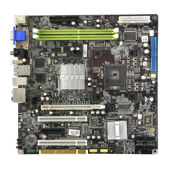
Page 14: Mainboard Layout
M:C S-Out PC I-E1 B:SPD IF-O ut SYSFAN 1 PCI3 BIOS Intel ALC880 PCI1 IC H7R JFP1 PCI2 BATT SATA4 SATA3 F_U S B2 F_USB1 SATA2 SATA1 C LR_C MO S1 J1394_1 PCI1 PCI2 945GT Speedster (MS-9632 v1.X) u-ATX Workstation Board... -
Page 15: Msi Special Feature
Getting Started MSI Special Feature Core Center (Optional) The Core Center is a new utility you can find in the application CD. The utility is just like your PC doctor that can detect, view and adjust the PC hardware and system status during real time operation. - Page 16 M S-9632 Workstation Board Left-side: Current system status In the left sub-menu, you can configure the settings of FSB & DOT by clicking the radio button in front of each item and make it available (the radio button will be lit as yellow when selected), use the “+”...
-
Page 17: Chapter 2. Hardware Setup
Hardware Setup Chapter 2 Hardware Setup This chapter provides you with the information about hardware setup procedures. While doing the installation, be careful in holding the components and follow the installation procedures. For some components, if you install in the wrong orientation, the components will not work properly. -
Page 18: Quick Components Guide
M S-9632 Workstation Board Quick Components Guide DDRII DIMMs, FDD1, p.2-11 ATX1, p.2-6 p.2-10 COM1,p.2-15 JPW1, p.2-10 Back Panel I/O, p.2-8 IDE1, p.2-11 CPUFAN1/ SYSFAN2, p.2-13 JCD1, CPU, p.2-3 p.2-14 PCI-E Slot, SYSFAN1, p.2-19 p.2-13 PCI Slots, JLPC1, BIOS p.2-19 p.2-15 JFP1, PCI-E Slot,... -
Page 19: Cpu (Central Processing Unit)
If you do not have the heat sink and cooling fan, contact your dealer to purchase and install them before turning on the computer. For more information on compatible components, please visit http://www.msi.com. tw/program/products/server/svr/pro_svr_qvl.php . Important 1. -
Page 20: Cpu & Cooler Set Installation
M S-9632 Workstation Board CPU & Cooler Set Installation 1. Place the CPU on top of the socket. Make sure to align the gold arrow on the CPU with the arrow key on the socket. 2. Push the CPU down until its pins securely fit into the socket. 3. - Page 21 Hardware Setup 5. Mount the cooler set (fan & heatsink bundled) on top of the CPU and fit it into the retention mechanism. 7. Connect the fan power cable from the 6. Secure the metal clips back to the mounted fan to the 3-pin fan power con- retention mechanism.
-
Page 22: Memory Population Rules
M S-9632 Workstation Board Memory The mainboard provides two 240-pin non-ECC DDRII 533/667 DIMMs and supports up to 4GB system memory. For more information on compatible components, please visit http://www.msi.com. tw/program/products/server/svr/pro_svr_qvl.php. DDRII 240-pin, 1.8V 64x2=128 pin 56x2=112 pin Single-Channel: All DIMMs in GREEN Memory Population Rules This mainboard supports DDRII 533/667 memory interface. -
Page 23: Installing Ddrii Modules
Hardware Setup Installing DDRII Modules 1. The memory module has only one notch on the center and will only fit in the right orientation. 2. Insert the DIMM memory module vertically into the DIMM slot. Then push it in until the golden finger on the memory module is deeply inserted in the socket. -
Page 24: Back Panel
M S-9632 Workstation Board Back Panel L-In RS-Out VGA Port Gb LAN M ou se L-Out CS-Out S-Video Keyboard DVI Port 1394 Port USB Ports SPDIF-Out M ouse/Keyboard Connector ® ® The standard PS/2 mouse/keyboard DIN connector is for a PS/2 mouse/keyboard. - Page 25 Hardware Setup Important After system resetting, we have to use hard keys to switch to the desired display device if the currently used type is different from the default type. (For example, if we use a VGA cable to connect the VGA port in the previous operation, the default display device will be the VGA.
-
Page 26: Ssi 24-Pin System Power Connector: Atx1
M S-9632 Workstation Board Power Supply SSI 24-Pin System Power Connector: ATX1 This connector allows you to connect an SSI power supply. To connect the SSI power supply, make sure the plug of the power supply is inserted pin 13 in the proper orientation and the pins are aligned. -
Page 27: Floppy Disk Drive Connector: Fdd1
Hardware Setup Connectors Floppy Disk Drive Connector: FDD1 This standard FDD connector supports 360K, 720K, 1.2M, 1.44M and 2.88M floppy disk types. FDD1 ATA133 Hard Disk Connector: IDE1 The mainboard has a 32-bit Enhanced PCI IDE and Ultra DMA 66/100/133 controller that provides PIO mode 0~4, Bus Master, and Ultra DMA 66/100/133 function. -
Page 28: Serial Ata Connectors: Sata1~Sata4
M S-9632 Workstation Board Serial ATA Connectors: SATA1~SATA4 SATA1~SATA4 are high-speed SATA II interface ports and support SATA II data rates of 300MB/s. Each SATA II connector can connect to 1 hard disk device and is fully compliant with Serial ATA 2.0 specifications. Please refer to the Appendix ICH7R RAID for detailed application. -
Page 29: Ieee 1394 Connector: J1394_1 (Optional)
Hardware Setup IEEE 1394 Connector: J1394_1 (Optional) The mainboard provides an IEEE1394 pinheader that allows you to connect IEEE 1394 ports via an external IEEE1394 bracket (optional). Pin Definition SIGNAL SIGNAL TPA+ TPA- Ground Ground J1394_1 TPB+ TPB- Cable power Cable power Key (no pin) Ground... -
Page 30: Cd-In Connector: Jcd1
M S-9632 Workstation Board CD-In Connector: JCD1 This connector is provided for CD-ROM audio. JCD1 Front Panel Connectors: JFP1 The mainboard provides one front panel connector for electrical connection to the ® front panel switches and LEDs. The JFP1 is compliant with Intel Front Panel I/O Connectivity Design Guide. -
Page 31: Fwh/Lpc Debugging Pin Header: Jlpc1
Hardware Setup FWH/LPC Debugging Pin Header: JLPC1 The pin header is for internal debugging only. JLPC1 Pin Definition SIGNAL SIGNAL JLPC1 LCLK Key (no pin) LRST# VCC3 LAD0 FID0_LRST LAD1 VCC5 LAD2 Key (no pin) LAD3 LFRAME# Serial Port Connector: COM1 The mainboard provides one 9-pin header as serial port. - Page 32 M S-9632 Workstation Board Front USB Connectors: F_USB1, F_USB2 The mainboard provides two USB 2.0 pinheaders (optional USB 2.0 bracket available) ® that are compliant with Intel I/O Connectivity Design Guide. USB 2.0 technology increases data transfer rate up to a maximum throughput of 480Mbps, which is 40 times faster than USB 1.1, and is ideal for connecting high-speed USB interface peripherals such as USB HDD, digital cameras, M P3 players, printers, mo- dems and the like.
-
Page 33: Clear Cmos Jumper: Clr_Cmos1
Hardware Setup Jumpers Clear CMOS Jumper: CLR_CMOS1 There is a CMOS RAM onboard that has a power supply from external battery to keep the data of system configuration. With the CMOS RAM, the system can automatically boot OS every time it is turned on. If you want to clear the system configuration, set the CLR_CMOS1 (Clear CMOS Jumper ) to clear data. -
Page 34: Bios Flash Jumper: Bios_Wp1
M S-9632 Workstation Board BIOS Flash Jumper: BIOS_WP1 This jumper is used to enable/disable the BIOS flash. W hen you intend to update the BIOS code, uncap this jumper first. Under normal operation, we suggest that you disable the BIOS flash by capping the BIOS_WP1 jumper to protect the system BIOS from virus infection. -
Page 35: Slots
Hardware Setup Slots PCI (Peripheral Component Interconnect) Express Slots PCI Express architecture provides a high performance I/O infrastructure for Desktop Platforms with transfer rates starting at 2.5 Giga transfers per second over a PCI Express x1 lane for Gigabit Ethernet, TV Tuners, 1394 controllers, and general pur- pose I/O. -
Page 36: Finger1 Golden Finger
M S-9632 Workstation Board FINGER1 Golden Finger The FINGER1 enables connection to the MS-95J9 Extension Card: (1) to provide the system with two additional 32-bit PCI slots and, (2) to extend the mainboard from u-ATX form factor to ATX form factor BIOS FINGER1 PCI1... -
Page 37: Chapter 3. Bios Setup
BIOS Setup Chapter 3 BIOS Setup This chapter provides information on the BIOS Setup program and allows you to configure the system for optimum use. You may need to run the Setup program when: ² An error message appears on the screen during the system booting up, and requests you to run SETUP. -
Page 38: Entering Setup
M S-9632 Workstation Board Entering Setup Power on the computer and the system will start POST (Power On Self Test) process. W hen the message below appears on the screen, press <F1> key to enter Setup. Press F1 to enter SETUP If the message disappears before you respond and you still wish to enter Setup, restart the system by turning it OFF and On or pressing the RESET button. -
Page 39: Control Keys
BIOS Setup Control Keys < ↑> Move to the previous item < ↓> Move to the next item < ←> Move to the item in the left hand < →> Move to the item in the right hand Select the item <Enter>... -
Page 40: The Menu Bar
M S-9632 Workstation Board The Menu Bar Main Use this menu for basic system configurations, such as time, date etc. Advanced Use this menu to set up the items of special enhanced features available on your system’s chipset. PC Health This entry monitors your hardware health status. - Page 41 BIOS Setup Main Date (mm:dd:yy) The date format is <Day>, <Month> <Date> <Year>. T ime (hh:mm:ss) The time format is <Hour> <Minute> <Second>. IDE Channel 0/1 Master/Slave Press PgUp/<+> or PgDn/<-> to select [Manual], [None] or [Auto] type. Note that the specifications of your drive must match with the drive table.
- Page 42 M S-9632 Workstation Board Drive A This item allows you to set the type of floppy drives installed. Base/Extended/Total M emory The three items show the memory status of the system. (Read-only)
-
Page 43: Advanced
BIOS Setup Advanced Advanced BIOS Features The sub-menu is used to configure chipset features for optimal system performance. - Page 44 M S-9632 Workstation Board Quick Power On Self Test Select [Enabled] to reduce the amount of time required to run the power-on self- test (POST). A quick POST skips certain steps. We recommend that you nor- mally disable quick POST. Better to find a problem during POST than lose data during your work.
- Page 45 BIOS Setup command after receiving it. Smaller clocks increase system performance while bigger clocks provide more stable system performance. DRAM RAS# to CAS# Delay This field allows you to set the number of cycles for a timing delay between the CAS and RAS strobe signals, used when DRAM is written to, read from or refreshed.
- Page 46 M S-9632 Workstation Board Video Connector This setting specifies the connector for video devices. Integrated Peripherals Press <Enter> to enter the sub-menu and the following screen appears: OnChip IDE Device Press <Enter> to enter the sub-menu and the following screen appears: IDE HDD Block Mode Block mode is also called block transfer, multiple commands, or multiple 3-10...
- Page 47 BIOS Setup sector read/write. If your IDE hard drive supports block mode (most new drives do), select [Enabled] for automatic detection of the optimal number of block read/writes per sector the drive can support. On-Chip Primary PCI IDE The setting disables/enables the onchip primary PCI IDE interface. IDE Primary Master/Slave PIO The IDE PIO (Programmed Input/Output) fields let you set a PIO mode for the IDE devices that the onboard IDE interface supports.
- Page 48 M S-9632 Workstation Board Onboard Device Press <Enter> to enter the sub-menu and the following screen appears: Planar Ethernet 1# / Planar Ethernet 2# These settings disable/enable the onboard Ethernet controller. Onboard LAN1 / LAN2 Boot ROM The items enable or disable the initialization of the onboard LAN Boot ROMs during bootup.
- Page 49 BIOS Setup Super IO Device Press <Enter> to enter the sub-menu and the following screen appears: Onboard FDC Controller Select [Enabled] if your system has a floppy disk controller (FDD) installed on the system board and you wish to use it. If you install add-on FDC or the system has no floppy drive, select [Disabled] in this field.
- Page 50 M S-9632 Workstation Board Power M anagement Setup Press <Enter> to enter the sub-menu and the following screen appears: PCI Express PME Function This setting specifies whether the system will be awakened by the PCI Express PME (Power Management Event). ACPI Function This item is to activate the ACPI (Advanced Configuration and Power Man- agement Interface) Function.
- Page 51 BIOS Setup Soft-Off by PWR-BTTN N This feature allows users to configure the power button function. Settings are: [Instant-Off] The power button functions as a normal power-on/-off button. [Delay 4 Sec.] W hen you press the power button, the computer enters the suspend/sleep mode, but if the button is pressed for more than four seconds, the computer is turned off.
- Page 52 M S-9632 Workstation Board Spread Spectrum W hen the motherboard’s clock generator pulses, the extreme values (spikes) of the pulses creates EMI (Electromagnetic Interference). The Spread Spectrum function reduces the EMI generated by modulating the pulses so that the spikes of the pulses are reduced to flatter curves.
-
Page 53: Pc Health
BIOS Setup PC Health Smart Fan Setting The sub-menu is used to control fan speeds for optimal system performance. 3-17... - Page 54 M S-9632 Workstation Board Smart SYSFan1 / CPUFan1 Temperature Select a temperature setting here, and if the temperature of the CPU/system climbs up to the selected temperature setting, the system will automatically increase the speed of the CPU/system fan to cool down the overheated CPU/ system.
-
Page 55: Security
BIOS Setup Security Set Supervisor Password Supervisor Password controls access to the BIOS Setup utility. Set User Password User Password controls access to the system at boot. Security Option This specifies the type of BIOS password protection that is implemented. Settings are described below: O p t i o n Desc riptio n... -
Page 56: System
M S-9632 Workstation Board System Sy stem Summary Press <Enter> to view the hardware specifications of your system. 3-20... - Page 57 BIOS Setup Halt On The setting determines whether the system will stop if an error is detected at boot. W hen the system stops for the errors preset, it will halt on for 15 seconds and then automatically resume its operation. Available options are: [All Errors] The system stops when any error is detected.
-
Page 58: Boot
M S-9632 Workstation Board Boot Removable Device Priority/Hard Disk Boot Priority/CD-ROM Boot Priority These settings allow users to set the priority of the specified devices. First press <Enter> to enter the sub-menu. Then you may use the arrow keys ( ↑↓ ) to select the desired device, then press <+>, <->... -
Page 59: Exit
BIOS Setup Exit Load Fail-Safe Defaults Use this menu to load the default values set by the BIOS vendor for stable system performance. Load Optimized Defaults Use this menu to load the default values set by the mainboard manufacturer specifi- cally for optimal performance of the mainboard. - Page 60 M S-9632 Workstation Board 3-24...
-
Page 61: Appendix A Intel Ich7R Sata Raid
Intel ICH7R SATA RAID Appendix A Intel ICH7R SATA RAID The ICH7R provides a hybrid solution that combines four independent SATAII ports for support of up to four Serial ATAII (Serial ATAII RAID) drives. It offers RAID level 0 (Striping), RAID level 1 (Mirroring and Duplexing), RAID level 5 (Block Interleaved Distrib- uted Parity), RAID level 10 (A Stripe of Mirrors) and ®... -
Page 62: Ich7R Introduction
M S-9632 Workstation Board ICH7R Introduction The ICH7R provides a hybrid solution that combines four independent SATAII ports for support of up to four Serial ATAII (Serial ATAII RAID) drives. Serial ATAII (SATAII) is the latest generation of the ATA interface. SATA hard drives deliver blistering transfer speeds up to 300MB/sec. -
Page 63: Bios Configuration
Intel ICH7R SATA RAID BIOS Configuration The Intel Matrix Storage Manager Option ROM should be integrated with the system BIOS on all motherboards with a supported Intel chipset. The Intel Matrix Stroage Manager Option ROM is the Intel RAID implementation and provides BIOS and DOS disk services. - Page 64 M S-9632 Workstation Board After pressing the <Ctrl> and <I> keys simultaneously, the following window will appear: (1) Create RAID Volume Select option 1 “Create RAID Volume” and press <Enter> key. The following screen appears. Then in the Name field, specify a RAID Volume name and then press the <TAB>...
- Page 65 Intel ICH7R SATA RAID In the Disk field, press <Enter> key and the following screen appears. Use <Space> key to select the disks you want to create for the RAID volume, then click <Enter> key to finish selection. Then select the strip value for the RAID array by using the “upper arrow” or “down arrow”...
- Page 66 M S-9632 Workstation Board Important Since you want to create two volumes (Intel Matrix RAID Technology), this default size (maximum) needs to be reduced. Type in a new size for the first volume. As an example: if you want the first volume to span the first half of the two disks, re-type the size to be half of what is shown by default.
- Page 67 Intel ICH7R SATA RAID (2) Delete RAID Volume Here you can delete the RAID volume, but please be noted that all data on RAID drives will be lost. Important If your system currently boots to RAID and you delete the RAID volume in the Intel RAID Option ROM, your system will become unbootable.
- Page 68 M S-9632 Workstation Board (3) Reset Disks to Non-RAID Select option 3 Reset Disks to Non-RAID and press <Enter> to delete the RAID volume and remove any RAID structures from the drives. The following screen appears: Press <Y> key to accept the selection. Important 1.
-
Page 69: Installing Software
Windows XP/2000 installation. † Existing Windows XP/2000 Driver Installation 1. Insert the MSI CD into the CD-ROM drive. 2. The CD will auto-run and the setup screen will appear. 3. Under the Driver tab, click on Intel IAA RAID Edition. -
Page 70: Installation Of Intel Matrix Storage Console
For this reason, you cannot remove or un-install this driver from the system after installation; however, you will have the ability to un-install all other non-driver components. Insert the MSI CD and click on the Intel IAA RAID Edition to install the software. Click on this item A-10... - Page 71 Intel ICH7R SATA RAID The InstallShield Wizard will begin automatically for installation showed as following: Click on the Next button to proceed the installation in the welcoming window. A-11...
- Page 72 M S-9632 Workstation Board The window shows the components to be installed. Click Next button to continue. After reading the license agreement in the following window, click Yes button to continue. A-12...
- Page 73 Intel ICH7R SATA RAID Select the folder in which you want the program to be installed in the following window, and click Next button to start installation. Select a program folder in the following window where you want Setup to add the program icon.
- Page 74 M S-9632 Workstation Board The following window appears to show the Intel Application Accelerator RAID Edition Setup installation status. Once the installation is complete, the following window appears. A-14...
-
Page 75: Raid Migration Instructions
Intel ICH7R SATA RAID RAID Migration Instructions The Intel Matrix Storage Console offers the flexibility to upgrade from a single Serial ATA (SATA) hard drive to RAID configuration when an additional SATA hard drive is added to the system. This process will create a new RAID volume from an existing disk. -
Page 76: Create Raid Volume From Existing Disk
M S-9632 Workstation Board Create RAID Volume from Existing Disk To create a RAID volume from an existing disk, choose Action --> Create RAID Volume from Existing Hard Drive. The Create RAID Volume from Existing Hard Drive Wizard pops up to lead you for the following procedure. - Page 77 Intel ICH7R SATA RAID (1) Step 1: Configure Volume Here you can configure the new RAID volume by entering the volume name, selecting the RAID level and strip size. † RAID Volume Name: A desired RAID volume name needs to be typed in where the ‘RAID_Volume1’ text currently appears above.
- Page 78 M S-9632 Workstation Board expensive (requiring read-in prior to write, in order to be able to calculate the correct parity information), or similar to RAID-1 writes. The write efficiency depends heavily on the amount of memory in the machine, and the usage pattern of the array.
- Page 79 Intel ICH7R SATA RAID (3) Select Member Hard Drive(s) Then select the member disk (the target disk) that you wish to use and then click “- -->” to move it to the Selected field. Then click Next to continue. Please note that the existing data on the selected hard drive(s) will be deleted permanently.
- Page 80 M S-9632 Workstation Board (4) Specify Volume Size Specify the amount of available array space to be used by the new RAID volume. You may enter the amount in the space or use the slider to specify. It is recommended you use 100% of the available space for the optimized usage.
- Page 81 Intel ICH7R SATA RAID (6) Start Migration The migration process may take up to two hours to complete depending on the size of the disks being used and the strip size selected. A dialogue window will appear stating that the migration process may take considerable time to complete, meanwhile a popup dialogue at the taskbar will also show the migration status.
-
Page 82: Missing Hard Drive Member
M S-9632 Workstation Board Degraded RAID Array A RAID 1, RAID 5 or RAID 10 volume is reported as degraded when one of its hard drive members fails or is temporarily disconnected, and data mirroring is lost. As a result, the system can only utilize theremaining functional hard drive member. To re- establish data mirroring and restore data redundancy, refer to the procedure below that corresponds to the current situation. - Page 83 Intel ICH7R SATA RAID 5. Exit Intel RAID Option ROM, and then reboot to W indows system. 6. W hen prompted to rebuild the RAID volume, click 'Yes'. 7. The Intel(R) Storage Utility will be launched. Right-click the new hard drive and select 'Rebuild to this Disk'.
- Page 84 M S-9632 Workstation Board A-24...
-
Page 85: Appendix B Realtek Alc880 Audio
Realtek ALC880 Audio Appendix B Realtek ALC880 Audio The Realtek ALC880 provides support for 8-channel audio output, including 2 Front, 2 Rear, 1 Center and 1 Subwoofer channel. ALC880 allows the board to attach 2, 4, 6 or 8 speakers for better surround sound effect. The section will tell you how to install and use 2-, 4-, 6- or 8-channel audio function on the board. -
Page 86: Installation For Windows 2000/Xp
M S-9632 Workstation Board Installing the Realtek HD Audio Driver You need to install the driver for Realtek ALC880 codec to function properly before you can get access to 2-, 4-, 6- or 8- channel audio operations. Follow the proce- dures described below to install the drivers for different operating systems. - Page 87 Realtek ALC880 Audio 3. Click Next to install the Realtek High Definition Audio Driver. Click here 4. Click Finish to restart the system. S el ec t t hi s option Click here...
-
Page 88: Software Configuration
M S-9632 Workstation Board Software Configuration After installing the audio driver, you are able to use the 2-, 4-, 6- or 8- channel audio feature now. Click the audio icon from the system tray at the lower-right corner of the screen to activate the HD Audio Configuration. It is also available to enable the audio driver by clicking the Azalia HD Sound Effect M anager from the Control Panel. -
Page 89: Sound Effect
Realtek ALC880 Audio Sound Effect Here you can select a sound effect you like from the Environment list. Load EQ Setting Reset EQ Setting EQ Setting On/Off Save Preset Delete EQ Setting You may choose the provided sound effects, and the equalizer will adjust automatically. If you like, you may also load an equalizer setting or make an new equalizer setting to save as an new one by using the “Load EQ Setting”... - Page 90 M S-9632 Workstation Board Equalizer Selection Equalizer frees users from default settings; users may create their owned preferred settings by utilizing this tool. 10 bands of equalizer, ranging from 100Hz to 16KHz. Save Reset The settings are saved 10 bands of equalizer permanently for future would go back to the de- fault setting...
- Page 91 Realtek ALC880 Audio Frequently Used Equalizer Setting Realtek HD Audio Sound Manager provides you certain optimized equalizer settings that are frequently used for your quick enjoyment. [How to Use It] Other than the buttons “Pop” “Live” “Club” & “Rock” shown on the page, to pull down the arrow in “Others”...
-
Page 92: Mixer
M S-9632 Workstation Board Mixer In the Mixer part, you may adjust the volumes of the rear and front panels individually. 1. Adjust Volume You can adjust the volume of the speakers that you pluged in front or rear panel by select the Realtek HD Audio rear output or Realtek HD Audio front output items. - Page 93 Realtek ALC880 Audio W hen you are playing the first audio source (for example: use W indows Media Player to play DVD/VCD), the output will be played from the rear panel, which is the default setting. Then you must to select the Realtek HD Audio front output from the scroll list first, and use a different program to play the second audio source (for example: use Winamp to play MP3 files).
- Page 94 M S-9632 Workstation Board 3. Playback control Tool Mute Playback device This function is to let you freely decide which ports to output the sound. And this is essential when multi- streaming playback enabled. M u te You may choose to mute single or multiple volume controls or to completely mute sound output.
- Page 95 Realtek ALC880 Audio 4. Recording control Recording device Tool Back Line In/Mic, Front Line In Realtek HD Audio Digital Input Tool Show the following volume controls This is to let you freely decide which volume control items to be displayed. Advanced controls.
- Page 96 M S-9632 Workstation Board 5. Recording If you want to use microphone to record, usually the microphone is connected to the MIC jack (the pink one) in the rear panel. You can start recording in this case. If you’d like to connect your microphone to the front audio panel. You may control the microphone volume by M ic Volume or front mic-in on the mixer.
-
Page 97: Audio I/O
Realtek ALC880 Audio Audio I/O In this tab, you can easily configure your multi-channel audio function and speakers. You can choose a desired multi-channel operation here. a. Headphone for the common headphone b. 2CH Speaker for Stereo-Speaker Output c. 4CH Speaker for 4-Speaker Output d. - Page 98 M S-9632 Workstation Board Correct M essage Assume to plug a headphone in the Green jack at back panel. The icon beside green jack become visible and the dialogue “connected device” pops up. Check the headphone, then click OK. As soon as OK is clicked, the icon beside green jack becomes “headphone”...
- Page 99 Realtek ALC880 Audio Global Connector Settings Click to access global connector settings. 1. M ute rear panel output when front headphone plugged in Once this item is checked, whenever front headphone is plugged, the music that is playing from the back panel, will be stopped. 2.
- Page 100 M S-9632 Workstation Board S/PDIF Short for Sony/Philips Digital Interface, a standard audio file transfer format. S/PDIF allows the transfer of digital audio signals from one device to another without having to be converted first to an analog format. Maintaining the viability of a digital signal pre- vents the quality of the signal from degrading when it is converted to analog.
- Page 101 Realtek ALC880 Audio Test Speakers You can select the speaker by clicking it to test its functionality. The one you select will light up and make testing sound. If any speaker fails to make sound, then check whether the cable is inserted firmly to the connector or replace the bad speakers with good ones.
-
Page 102: Microphone
M S-9632 Workstation Board Microphone In this tab you may set the function of the microphone. Select the Noise Suppres- sion to remove the possible noise during recording, or select Acoustic Echo Cancelltion to cancel the acoustic echo druing recording. Also, please use the drop-down list to choose the recording source from Realtek HD Audio real input or Realtek HD Audio front input. -
Page 103: 3D Audio Demo
Realtek ALC880 Audio 3D Audio Demo In this tab you may adjust your 3D positional audio before playing 3D audio applica- tions like gaming. You may also select different environment to choose the most suitable environment you like. B-19... -
Page 104: Information
M S-9632 Workstation Board Information In this tab it provides some information about this HD Audio Configuration utility, including Audio Driver Version, DirectX Version, Audio Controller & Audio Codec. You may also select the language of this utility by choosing from the Language list. Also there is a selection Show icon in system tray. - Page 105 Realtek ALC880 Audio Before you begin using the front panel function, please complete the following steps: 1. Please install the pinheaders of the front panel according to Chapter 2. 2. Select AC97 or Azalia in the BIOS setting (Chapter 3). 3.
-
Page 106: Hardware Setup
M S-9632 Workstation Board Hardware Setup Connecting the Speakers W hen you have set the Multi-Channel Audio Function mode properly in the software utility, connect your speakers to the correct phone jacks in accordance with the setting in software utility. n 2-Channel M ode for Stereo-Speaker Output Refer to the following diagram and caption for the function of each phone jack on the back panel when 2-Channel Mode is selected. - Page 107 Realtek ALC880 Audio n 4-Channel M ode for 4-Speaker Output Back Panel Description: Connect two speakers to back panel’s Line Out connector and two speakers to the real-chan- nel Line Out connector. 4-Channel Analog Audio Output Line In Line Out (Front channels) Line Out (Rear channels) Line Out (Center and Subwoofer channel, but no functioning in this mode) Optical SPDIF Out (in 7.1CH / 5.1CH)
- Page 108 M S-9632 Workstation Board n 6-Channel M ode for 6-Speaker Output Back Panel Description: Connect two speakers to back 6-Channel Analog Audio Output panel’s Line Out connector, two speakers to the rear-channel and two speakers to the cen- Line In ter/subwoofer-channel Line Out Line Out (Front channels) connectors.
- Page 109 Realtek ALC880 Audio n 8-Channel M ode for 8-Speaker Output Back Panel Description: Connect two speakers to back panel’s Line Out connector, two speakers to the rear-channel, two speakers to the c enter/ 8-Channel Analog Audio Output subwoofer-channel Line Out connectors, and two speakers to the side-channel Line Out Line Out (Side channels)
Need help?
Do you have a question about the 945GT Speedster and is the answer not in the manual?
Questions and answers