Table of Contents
Advertisement
INSTRUCTIONS for
These INSTRUCTIONS are for experienced operators. If you are not fully familiar with the principles of operation
and safe practices for arc welding equipment, we urge you to read our booklet, "Precautions and Safe Practices for
Arc Welding, Cutting and Gouging." Form 52-529. Do NOT permit untrained persons to install, operate, or maintain
this equipment. Do NOT attempt to install or operate this equipment until you have read and fully understand these
Instructions. If you do not fully understand these Instructions, contact your supplier for further information. Be
sure to read the Safety Precautions on page 3 before installing or operating this equipment.
Be sure this information reaches the operator.
You can get extra copies through your supplier.
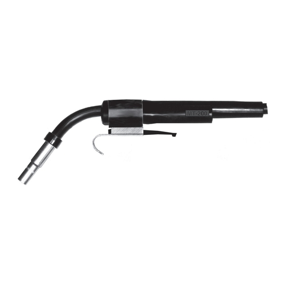
MT-200, MT-400 & MT-400EHD*
MIG WELDING GUN
WITH BAYONET CONNECTOR
F-12-778-H
June, 1999
*Extra Heavy Duty (EHD)
Advertisement
Table of Contents


Need help?
Do you have a question about the MT-400EHD and is the answer not in the manual?
Questions and answers