Table of Contents
Advertisement
Quick Links
Introduction
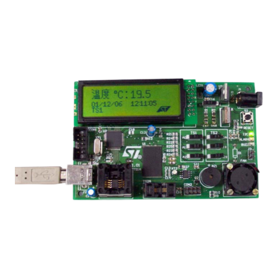
This document explains the functioning of the temperature sensor evaluation board which
consists of the ST72F651 microcontroller, STLM75 and STDS75 as temperature
and NAND Flash.
This board can operate in 2 modes:
■
Standalone / external power mode
■
USB powered mode
The configuration and operation of the evaluation board in both modes is explained in
different sections.
To select the desired mode, there is a power selection switch (S1) on the board which
enables the appropriate selection.
When this evaluation board is connected to the computer through a USB cable it also
functions as a mass storage device. The default state of the evaluation board is mass
storage mode. It switches over to temperature sensor mode using GUI.
Figure 1.
September 2007
Temperature sensor evaluation board
Temperature sensor evaluation board (STEVAL-IFS003V1)
Rev 1
UM0452
User manual
sensors,
www.st.com
1/30
Advertisement
Table of Contents

Related Manuals for ST ST72F651


Summary of Contents for ST ST72F651
-
Page 1: Figure 1. Temperature Sensor Evaluation Board (Steval-Ifs003V1)
User manual Temperature sensor evaluation board Introduction This document explains the functioning of the temperature sensor evaluation board which consists of the ST72F651 microcontroller, STLM75 and STDS75 as temperature sensors, and NAND Flash. This board can operate in 2 modes: ■... -
Page 2: Table Of Contents
Contents UM0452 Contents Abbreviations ..........5 Getting started . - Page 3 UM0452 Contents 4.5.1 Dynamic mode ..........22 4.5.2 NAND mode .
- Page 4 List of figures UM0452 List of figures Figure 1. Temperature sensor evaluation board (STEVAL-IFS003V1) ......1 Figure 2. Temperature sensor evaluation board .
-
Page 5: Abbreviations
UM0452 Abbreviations Abbreviations Table 1. Abbreviations Word Abbreviation BLDC Fan Brushless direct current fan Graphical User Interface Liquid crystal display Universal serial bus Real time clock °C Degree Centigrade Getting started Package contents The temperature sensor evaluation board includes the following items: ●... -
Page 6: Hardware Description
Getting started UM0452 Hardware description Figure 2. Temperature sensor evaluation board 2.2.1 Components Major blocks present on the board are: ● Temperature sensor SO-8 package: STDS75M2F/STLM75M2F ● Temperature sensor TSSOP-8 package: STDS75DS2F/STLM75DS2F ● Microcontroller : ST72F651AR6T1 ● NAND Flash : NAND512W3A0AN6 ●... -
Page 7: Power Supply Selection
UM0452 Getting started 2.2.2 Power supply selection The board can work in two different power supply modes. External power mode USB powered mode Selection of required power mode is done by the S1 switch. External power mode selection: To select for external supply mode place the switch as shown in Figure 3. -
Page 8: External Power Mode Of Evaluation Board
External power mode of evaluation board UM0452 External power mode of evaluation board This mode is also called standalone mode of the evaluation board. In this mode the board is supplied by an external power supply and continuously displays the time and temperature on LCD. -
Page 9: Address Configuration Of Ts1 Using The Switches
UM0452 External power mode of evaluation board 3.2.1 Address configuration of TS1 using the switches To select the temperature sensor 1 (TS1) follow these steps: Put all the switches of TS2 (A0#, A1#, A2#), to logic level 1.Condition shown in Figure Figure 6. -
Page 10: Address Configuration Of Ts2 Using The Switches
External power mode of evaluation board UM0452 After setting the address press the reset button (S2) present on the board. The board then functions showing the temperature and time on LCD. Note: If the address setting for TS1 is other than as shown in Table 2 or if the switches of TS2 are not all set to 1 (as shown in... -
Page 11: Values Of Temperature Sensor Registers In Standalone Mode
UM0452 External power mode of evaluation board Table 3. Switch settings for selecting a different address of TS2 on board Address Address 1 Address 2 Address 3 Address 4 Address 5 Address 6 Address 7 lines 0x90 0x92 0x94 0x96 0x98 0x9A 0x9C... -
Page 12: Sequence Of Operation Of Evaluation Board In Standalone Mode
USB power/GUI mode of evaluation board UM0452 date are configured in the RTC using GUI, the RTC keeps the time and date record. This time and date is displayed on the LCD at each powering sequence. Sequence of operation of evaluation board in standalone mode To use the board in standalone mode follow these steps: ●... -
Page 13: Powering Of Board In Gui Mode
UM0452 USB power/GUI mode of evaluation board Figure 8. GUI on start up with board not connected Powering of board in GUI mode Follow these steps in order to power the board in GUI mode: Adjust the power selection switch (S1) to select USB power mode as explained in Figure Plug the USB cable in the USB socket (J2) on the board. -
Page 14: Switching To Temperature Sensor Mode
USB power/GUI mode of evaluation board UM0452 Figure 9. Board connected to GUI and status changed to connected in status bar Switching to temperature sensor mode By default the board is in mass storage mode and as we open the GUI it shows the Mass storage mode in status bar. -
Page 15: Address Selection In Gui Mode
UM0452 USB power/GUI mode of evaluation board In this mode the LCD shows: ● Temperature written in Chinese and °C in first row ● Date and time in second row 4.3.1 Address selection in GUI mode In GUI mode we can address two different packages of temperature sensors: TS1 is the SO- 8 package of STDS75/STLM75 and TS2 is the TSSOP-8 package of STDS75/STLM75. -
Page 16: Address Checking Using Gui
USB power/GUI mode of evaluation board UM0452 Figure 11. Temperature sensor window 4.3.5 Address checking using GUI After the sensor package is selected and address is selected on the board (as stated in Section 4.3.1), the address is sent from the GUI through the drop down menu of Choose Address. -
Page 17: Figure 12. Address Error Message Display On Gui
UM0452 USB power/GUI mode of evaluation board Figure 12. Address error message display on GUI Figure 13. Active temperature sensor window 17/30... -
Page 18: Setting Of Temperature Sensor Registers
USB power/GUI mode of evaluation board UM0452 Table 5. Switch configuration for different address settings Address Address 1 Address 2 Address 3 Address 4 Address 5 Address 6 Address 7 lines 0x90 0x92 0x94 0x96 0x98 0x9A 0x9C 4.3.6 Setting of temperature sensor registers There are four different registers in the temperature sensor which can be configured. -
Page 19: Alarms
UM0452 USB power/GUI mode of evaluation board Temperature register: – This register is used to show the temperature measured by the sensor. – The ONCE button is used to read the temperature at any one instant. – The LOOP button is used to continuously measure and display the temperature. –... -
Page 20: Rtc Mode Of Gui
USB power/GUI mode of evaluation board UM0452 This alarm is used to indicate the behavior of the OS pin output of the temperature sensor. Its nature is dependent on the polarity selected in the configuration register. – If the polarity selected in the configuration register is LOW then: Default state: alarm LIGHTS UP Temperature rises above oversaturation temperature (Tos): alarm goes off Temperature falls below Thys: alarm LIGHTS UP... -
Page 21: Rtc Sync
UM0452 USB power/GUI mode of evaluation board 4.4.3 RTC SYNC There is a Sync button used to synchronize the RTC CLOCK with the system time. Press the Sync button to match the two clocks. The status of the RTC window is shown Figure Figure 15. -
Page 22: Dynamic Mode
USB power/GUI mode of evaluation board UM0452 4.5.1 Dynamic mode The dynamic mode of the plotter is used to plot the real time temperature variation with respect to time. In this mode the sensor measures the temperature at a selected frequency and in parallel plots that temperature on the graph. -
Page 23: Nand Mode
UM0452 USB power/GUI mode of evaluation board Figure 17. Plotter window with dynamic mode graph 4.5.2 NAND mode This mode is used for logging the temperature data in the NAND Flash present on the board. This logged data can be viewed at a later time in the graphical format in this window. -
Page 24: Behavior Of Leds And Buzzer
Behavior of LEDS and buzzer UM0452 10. In order to see the previously stored graphs, click on the folder icon in the toolbar and open the .tsg file to view. 11. If the user wants the graph to be plotted as soon as the data logging is stopped, then the checkbox "Receive Data After Logging"... -
Page 25: Application Leds
UM0452 Behavior of LEDS and buzzer Application LEDs There are three application specific LEDs on the board: C LED: This is a green LED (I C) which blinks whenever there is an I communication occurring in the application. Note: The temperature sensor and RTC are I C based devices. -
Page 26: Evaluation Board Schematic
Schematic UM0452 Appendix A Schematic Evaluation board schematic Figure 19. Schematic 26/30... -
Page 27: Bill Of Material
UM0452 Schematic Bill of material Table 6. Manufacturer’s Value/generic Manu- ordering code / Item Des. Ref. Package Supplier part number facturer orderable part number ST7 - MCU ST7F651 TQFP64 ST7F651AR6T1 NAND- NAND512W3A TSOP-48 NAND512W3A0AN6 Flash Voltage L7805 TO-220 L7805CV Regulator Real Time M41T81S SO-8... - Page 28 Schematic UM0452 Table 6. BOM (continued) Manufacturer’s Value/generic Manu- ordering code / Item Des. Ref. Package Supplier part number facturer orderable part number Power 09-03290-01 SPDT 090-03290-01 Farnell Switch Reset 4 pin push button Local Local Switch switch A1,A2 Address 09-03290-01 SPDT 09-03290-01...
-
Page 29: Revision History
UM0452 Revision history Table 6. BOM (continued) Manufacturer’s Value/generic Manu- ordering code / Item Des. Ref. Package Supplier part number facturer orderable part number Electrolytic 4.7 µF RB-2.25 Local Local Capacitor C13,C14 Capacitor 6 pF Local Local Capacitor 330 nF Local Local Revision history... - Page 30 No license, express or implied, by estoppel or otherwise, to any intellectual property rights is granted under this document. If any part of this document refers to any third party products or services it shall not be deemed a license grant by ST for the use of such third party products or services, or any intellectual property contained therein or considered as a warranty covering the use in any manner whatsoever of such third party products or services or any intellectual property contained therein.
Need help?
Do you have a question about the ST72F651 and is the answer not in the manual?
Questions and answers