
Related Manuals for Digital Equipment VAXstation 4000 Model 60


Summary of Contents for Digital Equipment VAXstation 4000 Model 60
- Page 1 VAXstation 4000 Model 60 to VAXstation 4000 Model 90 Upgrade Guide EK-VX690-UP. A01 Digital Equipment Corporation...
- Page 2 August 1992 The information in this document is subject to change without notice and should not be construed as a commitment by Digital Equipment Corporation. Digital Equipment Corporation assumes no responsibility for any errors that may appear in this document.
-
Page 3: Table Of Contents
Overview ............1–1 VAXstation 4000 Model 60 Product Description ......1–2 Contents of the Upgrade Kit . - Page 4 3–23 Figures 2–1 VAXstation 4000 Model 60 FRU Locations ......2–8 2–2 Avoid Touching This Area .
-
Page 5: About This Guide
About This Guide This guide describes how to upgrade a VAXstation 4000 Model Purpose of this 60 to a VAXstation 4000 Model 90, a faster, more powerful Guide VAXstation. The VAXstation 4000 Model 90 utilizes the new KA49 CPU module, which houses up to 128 Mbytes of SIMM main memory. - Page 6 Related guide, refer to the following documents: Documentation The following documents provide additional information relating to the VAXstation 4000 Model 60: VAXstation 4000 Options Installation Guide, EK-VAXOP-IN VAXstation 4000 Model 60 Service Information, EK-V466B-SV The following documents provide additional information relating...
- Page 7 About This Guide, Continued The following conventions are used in this guide: Conventions Used in this Guide Convention Meaning A name enclosed in a box in interactive Return examples indicates a key you press on the keyboard. Warning Warnings contain information to prevent personal injury.
-
Page 9: Overview Of The Vaxstation 4000 Model 60 And The Vaxstation 4000 Model
60 and the VAXstation 4000 Model 90 Overview The purpose of this chapter is to provide an overview of the Purpose VAXstation 4000 Model 60, and the VAXstation 4000 Model 90, and to provide a list of the contents of the upgrade kits. 1–1... -
Page 10: Vaxstation 4000 Model 60 Product Description
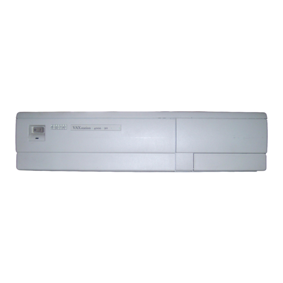
VAXstation 4000 Model 60 Product Description The VAXstation 4000 Model 60 system is a single-user engineering Product workstation, based on the KA46 system module. The Model 60 Description includes: An LK401 keyboard A VSXXX-GA mouse or VSXXX-AB tablet A monochrome or color video monitor... -
Page 11: Contents Of The Upgrade Kit
If a system started out as a VAXstation 3100 and was Note upgraded to a VAXstation 4000 Model 60, then it may not be upgraded to a VAXstation 4000 Model 90. The following is a list of the various PV71U upgrade kits that can... -
Page 12: Contents Of Pv71U-Af
VS4000 Owner’s Installation Guide – VS4000 Options Installation Guide – VS4000 Quick Installation Card EK-VX690-UP VAXstation 4000 Model 60 to VAXstation 4000 Model 90 Upgrade Guide 74-41856-08 A Medallion, VAXstation 4000 90 74-42680-02 Clamp, video board 12-36175-01 Disposable wrist strap Continued on next page 1–4... -
Page 13: Contents Of Pv71U-Ah
VS4000 Owner’s Installation Guide – VS4000 Options Installation Guide – VS4000 Quick Installation Card EK-VX690-UP VAXstation 4000 Model 60 to VAXstation 4000 Model 90 Upgrade Guide 74-41856-09 A Medallion, VAXstation 4000 90 SPXg 23-226E8-00 SPXg/gt diagnostic ROM 12-36175-01 Disposable wrist strap Continued on next page 1–5... -
Page 14: Contents Of Pv71U-Aj
VS4000 Owner’s Installation Guide – VS4000 Options Installation Guide – VS4000 Quick Installation Card EK-VX690-UP VAXstation 4000 Model 60 to VAXstation 4000 Model 90 Upgrade Guide 74-41856-10 A Medallion, VAXstation 4000 90 SPXgt 23-226E8-00 SPXg/gt diagnostic ROM 12-36175-01 Disposable wrist strap... -
Page 15: Vaxstation 4000 Model 90 Product Description
VAXstation 4000 Model 90 Product Description The VAXstation 4000 Model 90 is housed in a BA46 system Product enclosure. The KA49 system module with either 4-MB or 16-MB Description SIMM modules form the CPU/memory subsystem. The VAXstation 4000 Model 90 supports three graphics options: Option Description LCSPX... - Page 16 VAXstation 4000 Model 90 Product Description, Continued ROM-based diagnostics (field programmable flash ROMs) Product for: Description (continued) — Power-up self-test — User selected self-test — System level tests VMS software distribution by: — CDROM disk — TK tape — VMS Version 5-5.2 or higher —...
-
Page 17: Disassembly Of The Vaxstation 4000 Model 60 And Removal Of Components
The purpose of this chapter is to provide information so that Purpose Digital Services Engineers or knowledgeable Digital customers can disassemble an existing VAXstation 4000 Model 60 and remove the necessary components for the upgrade. Only Digital Services or qualified self-maintenance Caution personnel should perform this upgrade. - Page 18 Procedure Page Preparing VAXstation 4000 Model 60 for disassembly Shutting down peripherals and disconnecting cables Protecting against static Removing top cover of the VAXstation 4000 Model 60 Removing mass storage devices 2-10 Removing power supply 2-12 Removing lights and switches module...
-
Page 19: Preparing Vaxstation Model 60 For Disassembly
Preparing VAXstation Model 60 for Disassembly To run the SHOW CONFIG command, complete the following Run SHOW steps and refer to Example 2–1. CONFIG Command Step Action Press the Halt button located behind the door in the front of the system box. Results: The system displays the console prompt on the screen. -
Page 20: Examples 2–1 Typical Screen Display Of A Show Config Command (Model 60)
Preparing VAXstation Model 60 for Disassembly, Continued Example 2–1 Typical Screen Display of a SHOW CONFIG Command (Model 60) KA46-A V1.1-31E-V4.0 ! CPU type and firmware revision 08-00-2B-F3-31-03 ! Ethernet hardware address 16 MB ! Total memory DEVNBR DEVNAM INFO ------ ------ ----... -
Page 21: Shutting Down Peripherals And Disconnecting Cables
Shutting Down Peripherals and Disconnecting Cables After shutting down the operating system, turn the system Shut Down the peripherals off in the following order: System System unit Monitor Printer, modem, and any other equipment Expansion boxes The monitor power should be off for at least three minutes Warning before removing the power cord. -
Page 22: Protecting Against Static
Protecting Against Static The following rules must be adhered to while handling system Use the components: Antistatic Wrist Strap Wear a properly grounded antistatic wrist strap. Any module or device removed from the system unit must be placed on an antistatic mat. It is recommended that you have two antistatic mats for Note which to place all the removed devices and components. - Page 23 Protecting Against Static, Continued To protect against static, complete the following steps: Static Protection Method If you have... Then... An alligator clip Place the antistatic strap on your wrist. Attach the alligator clip to the metal latch located on the left center of the power supply.
-
Page 24: System Fru Locations
System FRU Locations Refer to Figure 2–1 for the VAXstation 4000 Model 60 FRU System FRU locations mentioned in this chapter. Locations The SPXgt, TURBOchannel adapter module, and any Note TURBOchannel option are not shown in Figure 2–1. Figure 2–1 VAXstation 4000 Model 60 FRU Locations... -
Page 25: Removing Top Cover Of The Vaxstation 4000 Model 60
Removing Top Cover of the VAXstation 4000 Model 60 Be careful not to touch the sharp edges of the system cover. Warning The top cover of the VAXstation 4000 Model 60 needs to be Remove the removed to gain access to the modules and components in the Top Cover BA46 system enclosure. -
Page 26: Removing Mass Storage Devices
Removing Mass Storage Devices Before removing any cables, be sure to label and note their Note locations. To remove the hard disk drive assembly from the BA46 system Remove the enclosure, complete the following steps: Hard Disk Drive Step Action Pull the colored tab on the H-bracket toward the front of the system. - Page 27 Removing Mass Storage Devices, Continued The removable media drive assembly may contain one of the Remove the following drives: Removable Media Drives RRD42 CDROM drive RX26 diskette drive TLZ06 cassette tape drive TZK10 QIC tape drive To remove the removable media drive assembly from the BA46 system enclosure, complete the following steps: Step Action...
-
Page 28: Removing Power Supply
Removing Power Supply Do not attempt to open the power supply. There are Warning dangerous voltages inside the power supply, and there are no user serviceable parts. To remove the power supply from the BA46 system enclosure, Remove the complete the following steps: Power Supply Step Action... -
Page 29: Removing Lights And Switches Module
Removing Lights and Switches Module When removing the lights and switches module, be very Caution careful to avoid touching the system module (CPU) in the area shown in Figure 2–2. Touching the board in the area indicated could damage some of the components on the board. - Page 30 Removing Lights and Switches Module, Continued To remove the lights and switches module from the BA46 system Remove the enclosure, complete the following steps: Lights and Switches Module Step Action Disconnect the module connector from the system module by lifting up on the module where it overlaps the system module.
-
Page 31: Removing Graphics Module (If Applicable)
Removing Graphics Module (if applicable) If you have graphic capabilities in your VAXstation 4000 Model Graphics 60, then you may find one of the following graphics module types: Module Types LGC (one board) The LGC must be replaced with a new LCSPX graphics module during the upgrade along with the video board clamp from the kit. - Page 32 Removing Graphics Module (if applicable), Continued To remove the graphics module(s) from the BA46 system Remove the enclosure, complete the following steps: Graphics Module(s) If you have an... Then... Release the graphics module latches and lift the module out of the BA46 enclosure. Place the LCG graphics module on the antistatic mat.
- Page 33 Removing Graphics Module (if applicable), Continued Remove the If you have Graphics an... Then... Module(s) SPXgt (continued) Remove the E-clip located closest to the tail bracket holding the SPXgt assembly together. CAUTION Do not lift from the tail bracket. To prevent the frame buffer from bending and any damage occurring, gently lift by grasping the center of the module.
- Page 34 Removing Graphics Module (if applicable), Continued Remove the If you have Graphics an... Then... Module(s) SPXgt (continued) (cont.) Remove the video board clamp from the KA46 system module by spreading the sides of the video board clamp away from the connector, and then lift the clamp off and away from the system module.
-
Page 35: Removing Synchronous Communications Option (If Applicable)
Removing Synchronous Communications Option (if applicable) To remove the synchronous communications option from the BA46 Remove the system enclosure, complete the following steps: Synchronous Communications Option Step Action Lift the synchronous communications option away from the system module at the point directly behind the SCSI connector. -
Page 36: Removing Turbochannel Adapter Module And Option (If Applicable)
Removing TURBOchannel Adapter Module and Option (if applicable) To remove the TURBOchannel adapter module and option from Remove the the BA46 system enclosure, complete the following steps: TURBOchannel Adapter and Option Step Action Remove the two screws holding the filler plate on the TURBOchannel option located at the rear of the enclosure. -
Page 37: Removing Ka46 System Module (Cpu)
Removing KA46 System Module (CPU) To remove the KA46 system module from the BA46 system Remove the enclosure, complete the following steps: KA46 System Module Step Action Disconnect the SCSI and power cables from the system module. Remove the system module (CPU) by lifting the front slightly, so that it clears the two stops at the front right and left of the module. -
Page 38: Removing Ms44 Memory Simms
Removing MS44 Memory SIMMs Memory components can easily be damaged by static Cautions electricity. An antistatic wrist strap must always be worn when removing or installing memory components. Memory modules must always be removed starting from the rear of the module. You must remove any modules at the back of the board and work toward the front of the board. -
Page 39: Removing A Ms44 Memory Simm (Model 60)
Removing MS44 Memory SIMMs, Continued Remove Figure 2–3 Removing a MS44 Memory SIMM (Model 60) the MS44 Memory SIMMs (continued) MLO-008154 2–23... -
Page 40: Removing Ethernet Rom
Removing Ethernet ROM If the same unique Ethernet address is not required, for Note example, for a standalone system, then do not remove the Ethernet ROM. Consult with the customer. The Ethernet ROM is the only socketed 16-pin chip on the system module. -
Page 41: Swapping Medallions
Swapping Medallions To swap the medallion on the VAXstation 4000 Model 60 to the Swap the new medallion, complete the following steps: Medallions Step Action Squeeze the tabs on the medallion and pull the medallion away from the BA46 system enclosure. -
Page 43: Installation Of Upgrade Components And Reassembly Of The New Vaxstation 4000 Model 90 Overview
Chapter 3 Installation of Upgrade Components and Reassembly of the New VAXstation 4000 Model 90 Overview The purpose of this chapter is to provide information so that Purpose Digital Services Engineers or knowledgeable Digital customers can install the upgrade components and reassemble the VAXstation 4000 Model 90. - Page 44 Overview, Continued The following table summarizes the recommended installation Summary of process and lists the applicable page number for reference to that Installation procedure. Process Found Procedure Page Installing Ethernet ROM Installing MS44 memory SIMMs Installing KA49 system module (CPU) 3-10 Installing TURBOchannel adapter module and option 3-11...
-
Page 45: System Fru Locations
System FRU Locations Refer to Figure 3–1 for the VAXstation 4000 Model 90 FRU System FRU locations mentioned in this chapter. Locations The TURBOchannel adapter module and any Note TURBOchannel option are not shown in Figure 3–1. The references of "Note" and "Item" that appear in Figure 3–1 are used in the VAXstation 4000 Model 90 Service Information Guide and do not apply to this guide. -
Page 46: Vaxstation 4000 Model 90 Fru Locations
System FRU Locations, Continued Figure 3–1 VAXstation 4000 Model 90 FRU locations 5 4 2 0 8 5 4 - 0 2 7 0 2 8 1 0 7 - 0 1 2 4 - P L A N E C O V E R A S S E M B L Y F R A M E B U F F E R S E E N O T E 4... -
Page 47: Installing Ethernet Rom
Installing Ethernet ROM If the same unique Ethernet address is not required, for Note example, for a standalone system, then do not install the Ethernet ROM. Consult with the customer. To install the Ethernet ROM in the new KA49 system module, Install the complete the following steps: Ethernet ROM... -
Page 48: Installing Ms44 Memory Simms
Installing MS44 Memory SIMMs The memory modules are keyed and can be installed in Caution one direction only. Excessive force applied to the modules when they are not properly aligned with the connector can cause permanent damage to either the modules or to the connector. -
Page 49: Memory Slots In The Model 90
Installing MS44 Memory SIMMs, Continued MS44 Memory Figure 3–2 Memory Slots in the Model 90 Slots (Model 90) (continued) MLO-008750 Continued on next page 3–7... -
Page 50: Memory Configurations (Model 90)
Installing MS44 Memory SIMMs, Continued For memory configurations, refer to Table 3–1. Memory Configurations (Model 90) Table 3–1 Memory Configurations (Model 90) Desired Memory Boards to Add Slot Number 16 MB Four 4-MB All 0s or all 1s 32 MB Eight 4-MB 64 MB Four 16-MB... -
Page 51: Installing The First Ms44 Memory Simm (Model 90)
Installing MS44 Memory SIMMs, Continued Install the Figure 3–3 Installing the First MS44 Memory SIMM (Model 90) MS44 Memory SIMMs (continued) MLO-008749 3–9... -
Page 52: Installing The Ka49 System Module (Cpu)
Installing the KA49 System Module (CPU) To install the KA49 system module in the BA46 system enclosure, Install the complete the following steps: KA49 System Module Step Action Align the five slots in the module with the five latches on the base of the system enclosure. -
Page 53: Installing Turbochannel Adapter Module And Option (If Applicable)
Installing TURBOchannel Adapter Module and Option (if applicable) To install the TURBOchannel adapter module and option in the Install the BA46 system enclosure, complete the following steps. Refer to TURBOchannel the VAXstation 4000 Options Installation Guide for additional Adapter information. Module and Option Step... -
Page 54: Installing Synchronous Communications Option (If Applicable)
Installing Synchronous Communications Option (if applicable) To install the synchronous communications option in the BA46 Install the system enclosure, complete the following steps and refer to Synchronous Figure 3–4. Communications Option Step Action Slide the synchronous communications option firmly towards the back of the system enclosure. Make sure that the two small openings in the metal bracket under the rear 50-pin connector slide onto the plastic bracket along the top rear of the system module. -
Page 55: Swapping Spxg/Gt Diagnostic Rom (If Applicable)
Swapping SPXg/gt Diagnostic ROM (if applicable) When swapping the diagnostic ROM from the graphics Cautions module, antistatic precaution must be adhered to. Before removing and installing the diagnostic ROM, be sure to note the orientation of the IC chip keyway in relation to the chip IC socket. -
Page 56: Installing Graphics Module (If Applicable)
Installing Graphics Module (if applicable) The refresh rate for the LCSPX and SPXg are switch Note selectable, 66 or 72 Hz. They must match the refresh cycle of the monitor. If the refresh rate needs to be changed, then complete the Setting the following steps: Refresh Rate... -
Page 57: Installing Graphics Module(S)
Installing Graphics Module (if applicable), Continued To install the graphics module(s) in the BA46 system enclosure, Install the complete the following steps: Graphics Module(s) If you have an... Then... LCSPX Install the video board clamp that came with the kit. Make sure the two slots in the metal bracket on the graphics module line up with the two notches on the plastic bracket... - Page 58 Installing Graphics Module (if applicable), Continued Install the SPXg Graphics Install the video board clamp on the KA49 Module(s) system module that was removed from the (continued) KA46 system module. Make sure the two slots in the metal bracket on the graphics module line up with the two notches on the plastic bracket along the top rear of the system module.
- Page 59 Installing Graphics Module (if applicable), Continued Install the If you have Graphics an... Then... Module(s) SPXgt (continued) Install the video board clamp on the KA49 system module that was removed from the KA46 system module. Make sure the two slots in the metal bracket on the graphics module line up with the two notches on the plastic bracket along the top rear of the system module.
-
Page 60: Installing Lights And Switches Module
Installing Lights and Switches Module When installing the module, be sure to align the module Note jacks and switches with the cutouts in the front panel. To install the lights and switches module in the BA46 system Install the enclosure, complete the following steps: Lights and Switches Module... -
Page 61: Installing Power Supply
Installing Power Supply To install the power supply in the BA46 system enclosure, Install the complete the following steps: Power Supply Step Action Align the two guides (one on the right front and one on the right rear of the supply) with the slots on the system enclosure. -
Page 62: Installing Mass Storage Devices
Installing Mass Storage Devices To install the hard disk drive assembly in the BA46 system Install the Hard enclosure, complete the following steps: Disk Drive Step Action Connect both the SCSI and dc power cables to the drive(s). Snap the bracket assembly back into place. Check the cable routing. -
Page 63: Restoring The System
Restoring the System To restore the system, complete the following steps: Restore the System Step Action Replace the system cover. Align the hinged teeth of the cover with the hinged teeth on the left side of the BA46 system enclosure and lower the cover until it clicks into place. - Page 64 Restoring the System, Continued To run the SHOW CONFIG command, complete the following Run SHOW steps and refer to Example 3–1. CONFIG Command Step Action Press the Halt button located behind the door in the front of the system box. Results: The system displays the console prompt on the screen.
- Page 65 Restoring the System, Continued Example 3–1 Typical Screen Display of a SHOW CONFIG Command (Model 90) KA49-A V0.0-051-V4.0 ! System type and firmware revision 08-00-2B-F3-31-03 ! Ethernet hardware address 16 MB ! Total memory DEVNBR DEVNAM INFO ------ ------ ---- ! Non-volatile RAM LCSPX Highres - 8 Plane...
-
Page 67: Appendix A Packing Instructions And Upgrade Return Forms
Appendix A Packing Instructions and Upgrade Return Forms Packing Instructions The Digital Services representative should work together with Overview the customer to ensure that the hardware is packaged properly for return to Digital and that the proper return forms in this appendix are completed. -
Page 69: Digital Services Upgrade Worksheet
Digital Services Upgrade Worksheet This form acts as a verification of the work performed on the system and as a check on the procedures used. Please fill out this form and return it to your Contract Administrator for updating the customer’s contract. Customer: System Serial Number: Old System Model Number:... -
Page 71: Installation Receipt-Customer Copy
Installation Receipt—Customer Copy For VAXstation 4000 Model 60 upgrade to VAXstation 4000 Model 90. This form acts as a customer receipt and as verification for Digital Services that the upgrade was completed. Digital Complete both copies of this form. Then, give a copy Services: to the customer and a copy to the local CAS office... - Page 72 Installation Receipt—Customer Copy, Continued New CPU Module Serial Number: Installation was performed on this date: Module Packed for Return: Customer Name: Phone Number: Customer Signature: Digital Services Representative Signature: Continued on next page A–6...
-
Page 73: Installation Receipt-Digital Services Copy
Installation Receipt—Digital Services Copy For VAXstation 4000 Model 60 upgrade to VAXstation 4000 Model 90. This form acts as a customer receipt and as verification for Digital Services that the upgrade was completed. Digital Complete both copies of this form. Then, give a copy Services: to the customer and a copy to the local CAS office... - Page 74 Installation Receipt—Digital Services Copy, Continued New CPU Module Serial Number: Installation was performed on this date: Module Packed for Return: Customer Name: Phone Number: Customer Signature: Digital Services Representative Signature: Continued on next page A–8...
-
Page 75: Return Material Checklist
Return Material Checklist For VAXstation 4000 Model 60 upgrade to VAXstation 4000 Model 90. This form must be filled out and returned with the old modules to ensure that the customer does not incur a penalty charge. Date: Return Authorization (RA) Number:... - Page 76 Return Material Checklist, Continued HARDWARE BEING RETURNED: System Number from Rear of System Serial Number Include This Form With Your Module Return Continued on next page A–10...
-
Page 77: Customer Administrative Services District Offices
Customer Administrative Services District Offices Name, Location Phone Number Allegheny District, Pittsburgh (412) 244–7410 Carolinas District, Columbia (803) 798–6477 Chicago District, Chicago (312) 806–2478 Connecticut District, Meriden (203) 634–5325 CSS District, Nashua (603) 884–6549 DECdirect District, Nashua (603) 884–9115 Florida District, Tampa (813) 882–6822 Greater Boston District, Waltham (617) 895–5455... - Page 78 Customer Administrative Services District Offices, Continued Name, Location Phone Number Southeast District, Atlanta (404) 257–2282 Southern California District, Costa (714) 850–7606 Mesa South Texas District, Houston (713) 953–3918 Southwest District, Tempe (602) 894–4747 Upstate New York District, (716) 385–7152 Rochester U.S.
-
Page 79: Index
Index Back up software, 2–1 Graphics options, Model 60 LGC, 2–15 SPXg, 2–15 SPXgt, 2–15 CAS district offices, A–11 options, Model 90 Checklist, return material, A–9 LCSPX, 1–7, 3–14 SPXg, 1–7, 3–14 SPXgt, 1–7, 3–14 Digital return forms, A–1 Digital Services worksheet, A–3 District offices, CAS, A–11 Hard disk drive, 2–10, 3–20 Drives... - Page 80 Removal procedures (cont’d) removing mass storage devices, 2–10 to 2–11 removing MS44 Memory SIMMs, 2–22 KA46 system module, 2–21 removing power supply, 2–12 KA49 system module, 1–7, 3–10 removing synchronous communications option, 2–19 removing top cover, 2–9 removing TURBOchannel adapter LCSPX graphics option, 1–7 module and option, 2–20 LGC graphics module, 2–15...
- Page 81 VAXstation 4000 See also Models models, 1–1 Worksheet, Digital Services, A–3 Wrist strap, 2–6 Index–3...
Need help?
Do you have a question about the VAXstation 4000 Model 60 and is the answer not in the manual?
Questions and answers