
Related Manuals for Digital Equipment VAXstation 3100 Series


Summary of Contents for Digital Equipment VAXstation 3100 Series
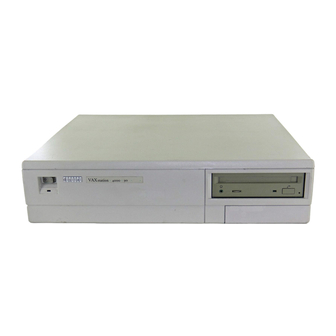
- Page 1 Order Number: EK-VX463-IN. A01 VAXstation 3100 Family to VAXstation 4000 Model 60/90 Upgrade Guide...
- Page 2 July, 1993 The information in this document is subject to change without notice and should not be construed as a commitment by Digital Equipment Corporation. Digital Equipment Corporation assumes no responsibility for any errors that may appear in this document.
-
Page 3: Table Of Contents
Contents ........... . . Preface 1 Preparing for the System Upgrade Upgrading Your Options to the VAXstation 4000 . - Page 4 3 Removing Options from a Model 40 and 48 Workstation Purpose ......... 3–1 Chapter Content .
- Page 5 Index Figures Typical Screen Display of a SHOW DEVICE Command ..1–1 1–5 Disconnecting the System Unit and Monitor Cables ..1–2 1–6 Removing the VAXstation 3100 System Unit Cover ..1–3 1–7 Attaching the Antistatic Wrist Strap to the System Unit .
- Page 6 Removing the Scanline Coprocessor from the Model 76 4–6 System ......... . 4–11 Removing the Ethernet ROM from the Model 76 System .
-
Page 7: Preface
Preface This guide describes how to upgrade the VAXstation 3100 family Purpose of this of systems to a VAXstation 4000 Model 60 or Model 90 only. The Guide VAXstation 3100 family consists of five models–30, 38, 40, 48, and 76. You perform the upgrade by removing supported options from the VAXstation 3100 system unit and installing them in the VAXstation 4000 system unit. -
Page 8: Options You Can Upgrade
The guide contains five chapters, as follows: Structure of this Guide Chapter Content Options you can upgrade; preparing the VAXstation 3100 system. Removing options from the Model 30 and 38. Removing options from the Model 40 and 48. Removing options from the Model 76. Installing the VAXstation 4000 system;... -
Page 9: Preparing For The System Upgrade
Preparing for the System Upgrade Upgrading Your Options to the VAXstation 4000 Table 1–1 lists the options you can move from a VAXstation 3100 system to a VAXstation 4000 system. Table 1–1 Options You Can Upgrade Monitors: Comments: VR262-Ax 60 Hz (Supported on Model 60 only) VR290-Dx 60 Hz (Supported on Model 60 only) VR297-Dx... - Page 10 Upgrading Your Options to the VAXstation 4000 Table 1–1 (Cont.) Options You Can Upgrade Monitors: Comments: VRT19-Hx 66/72 Hz Fixed Disk Drives: Comments: RZ23L RZ24 RZ24L RZ25 RZ55 Supported on expansion box only RZ56 Supported on expansion box only RZ57 Supported on expansion box only RZ58 Supported on expansion box only...
- Page 11 Upgrading Your Options to the VAXstation 4000 Table 1–1 (Cont.) Options You Can Upgrade Input Devices: Comments: LK401-xx Keyboard VSXXX-AA/GA Mouse VSXXX-AB Tablet Expansion Boxes: SZ03 SZ12 SZ16 RZ5X Graphics You cannot upgrade the graphics module from your VAXstation 3100 system to the VAXstation 4000 system. Preparing for the System Upgrade 1–3...
-
Page 12: Recording Vaxstation 3100 System Information
Recording VAXstation 3100 System Information Recording VAXstation 3100 System Information Refer to the VMS Installation and Operations Manual for the Shut Down the proper operating system shutdown procedure. Software Before you begin the upgrade you need to record the system Enter the Ethernet address (only if you are moving the Ethernet ROM to SHOW DEVICE... -
Page 13: Typical Screen Display Of A Show Device Command
Recording VAXstation 3100 System Information Figure 1–1 Typical Screen Display of a SHOW DEVICE Command Ethernet Hardware Address Device Name SCSI Bus SCSI ID Setting Device Type MLO-010942 Preparing for the System Upgrade 1–5... -
Page 14: Removing The System Unit Cover
Removing the System Unit Cover Removing the System Unit Cover After shutting down the operating system and recording Turn Off the the VAXstation 3100 system information, turn the system System peripherals off in the following order: 1. Expansion boxes 2. Printer, modem, and other equipment 3. -
Page 15: Remove The Cover
Removing the System Unit Cover To remove the system unit cover from the VAXstation 3100 Remove the workstation, do the following and refer to Figure 1–3: Cover 1. Using a Phillips screwdriver, loosen the two captive screws at the back of the system unit on the outside edges. Do not remove the screws. -
Page 16: Protecting Against Static Discharge
Protecting Against Static Discharge Protecting Against Static Discharge Caution: To eliminate any static charge that you may have built up, touch the top of the power supply in the system unit. This discharges any static electricity. Always wear an antistatic wrist strap when working inside the system unit to avoid damage caused by static discharge. -
Page 17: Checking The Vaxstation 3100 Model Number
Checking the VAXstation 3100 Model Number Checking the VAXstation 3100 Model Number After you have disconnected the cables and before beginning the upgrade, check the model number of the system you are upgrading. Each system has a model code number stamped on the rear of the system unit. -
Page 19: Removing Options From A Model 30 And 38 Workstation
Removing Options from a Model 30 and 38 Workstation The purpose of this chapter is to provide upgrade information so Purpose that a Digital service representative or knowledgeable Digital customer can upgrade an existing VAXstation 3100 Model 30 or 38 workstation to a VAXstation 4000 Model 60 or 90 workstation. Caution: Only a Digital service representative or qualified self–maintenance customer should perform this... -
Page 20: Removing Fixed Disk Drives
Removing Fixed Disk Drives Removing Fixed Disk Drives There are several possible drive plate configurations for the Typical Drive Model 30 and 38, including two different types of drive plates. Plate Layout There are also different kinds of SCSI mass storage controllers depending on the model you are upgrading. - Page 21 Removing Fixed Disk Drives Remove all the supported RZ2x disk drives from the drive plate. Remove RZ2x Two of these drives can be installed into the VAXstation 4000 Disk Drives system unit. To remove an RZ2x disk drive from the model 30 or 38, do the following and refer to Figure 2–2: 1.
-
Page 22: Removing Rz2X Fixed Disk Drives From The Drive Plate
Removing Fixed Disk Drives Figure 2–2 Removing RZ2x Fixed Disk Drives from the Drive Plate RZxx Hard Disk SCSI Mass Storage Controller Module Drive Plate Lever MLO-010908 Note If there are three disk drives on the drive plate, you must remove the mass storage controller module from the drive plate to remove the third drive. -
Page 23: Remove The Mass Storage Controller
Removing Fixed Disk Drives To remove the mass storage controller module from the Model 30 Remove the or 38, do the following and refer to Figure 2–3 and Figure 2–4: Mass Storage Controller 1. Loosen the captive screw on the SCSI mass storage controller module. -
Page 24: Removing The Scsi Mass Storage Controller Module
Removing Fixed Disk Drives Figure 2–4 Removing the SCSI Mass Storage Controller Module Slide Mount (1) SCSI System Cable Drive Plate Slide Mounts (2) SCSI System Port Latches SCSI Mass Storage Controller Module Captive Screw Post Locks (Underneath Module) MLO-005533 Caution: When you remove the lower drive plate from the system unit, do not make contact with the circuit boards under... -
Page 25: Remove The Drive Plate
Removing Fixed Disk Drives To remove the drive plate, do the following and refer to Remove the Figure 2–5: Drive Plate 1. Disconnect the internal power cable from the internal power supply. 2. Disconnect the SCSI system cable from the SCSI system port (if it has not already been done). -
Page 26: Removing The Drive Plate From A Model 30 Or 38 System
Removing Fixed Disk Drives Figure 2–5 Removing the Drive Plate from a Model 30 or 38 System SCSI System Cable Internal Power Cable Captive Screws (2) Power Supply Cable SCSI System Port Captive Screws (3) Drive Plate Slide Mount Screws (3) Slide Mount Openings MLO-005536 2–8 Removing Options from a Model 30 and 38 Workstation... -
Page 27: Removing The Ethernet Rom
Removing Fixed Disk Drives Before You Continue If you are not upgrading the Ethernet ROM, go to Chapter 5 to complete this upgrade. Continue with the next section, Removing the Ethernet ROM, only if you want to maintain the same Ethernet address in the VAXstation 4000 system. -
Page 28: Scanline Coprocessor Mounting Brackets
Removing the Ethernet ROM 2. Remove the scanline coprocessor from the four post locks by pulling back the post lock tabs. Caution: Do not grasp the scanline coprocessor module by the corners when you are lifting it up to remove it from the system board. -
Page 29: Removing The Scanline Coprocessor From The Model 30 And 38 System
Removing the Ethernet ROM Figure 2–7 Removing the Scanline Coprocessor from the Model 30 and 38 System Connectors MLO-010911 3. Grasp the center of the scanline coprocessor module next to the two connectors, and lift it up and off the system board. 4. -
Page 30: Remove The Ethernet Rom
Removing the Ethernet ROM Remove the Ethernet ROM Caution When removing the Ethernet ROM from the system board, antistatic precaution must be adhered to. Refer to Figure 2–8 to remove the Ethernet ROM. Figure 2–8 Removing the Ethernet ROM from the Model 30 and 38 System MLO-010910 Set the Ethernet ROM on an antistatic mat until you are ready... -
Page 31: Removing Options From A Model 40 And 48 Workstation
Removing Options from a Model 40 and 48 Workstation The purpose of this chapter is to provide upgrade information so Purpose that a Digital service representative or knowledgeable Digital customer can upgrade an existing VAXstation 3100 Model 40 or 48 workstation to a VAXstation 4000 Model 60 or 90 workstation. Caution: Only a Digital service representative or qualified self–maintenance customer should perform this... -
Page 32: Removing Fixed Disk Drives
Removing Fixed Disk Drives Removing Fixed Disk Drives There are several possible drive plate configurations for the Typical Drive Model 40 and 48, including two different types of drive plates. Plate Layout There are also different kinds of SCSI mass storage controllers depending on the model being upgraded. -
Page 33: Common Configuration For A Model 40 And 48 Drive
Removing Fixed Disk Drives Figure 3–1 Common Configuration for a Model 40 and 48 Drive Plate System Module Module RRD40 Adapter Module SCSI-B Power Supply RZ2x RZ2x RZ2x (System Disk) Upper Drive Plate RRD40 TZ30 Drive Drive Power Lower Drive Plate Data MLO-010909 Removing Options from a Model 40 and 48 Workstation 3–3... -
Page 34: Remove The Upper Drive Plate
Removing Fixed Disk Drives To remove the upper drive plate, do the following and refer to Remove the Figure 3–2 and Figure 3–3: Upper Drive Plate 1. Disconnect the SCSI signal cables from all the RZ2x disk drives. 2. Disconnect the internal power cables from all the RZ2x disk drives. -
Page 35: Disconnecting The Scsi And Power Cables
Removing Fixed Disk Drives Figure 3–2 Disconnecting the SCSI and Power Cables SCSI Signal Cable Internal Power Connector Internal Power Cable SCSI-B Cable MLO-006515 Removing Options from a Model 40 and 48 Workstation 3–5... -
Page 36: Remove Rz2X Disk Drives
Removing Fixed Disk Drives Figure 3–3 Removing the Upper Drive Plate from the Model 40 and 48 System Captive Captive Screws (2) Screws (2) Upper Drive Plate Captive Screw MLO-006507 Remove the supported RZ2x disk drives from the upper drive Remove RZ2x plate. -
Page 37: Removing Rz2X Fixed Disks From The Drive Plate
Removing Fixed Disk Drives Figure 3–4 Removing RZ2x Fixed Disks from the Drive Plate RZxx Hard Disk Upper Drive Plate MLO-010918 You do not need to save the screws and grommets removed from the drive plate. The VAXstation 4000 upgrade kit includes special mounting plates for the RZ2x disk drives. -
Page 38: Removing The Ethernet Rom
Removing the Ethernet ROM Removing the Ethernet ROM To access the Ethernet ROM you must remove the lower drive plate and the scanline coprocessor. Caution: When you remove the lower drive plate from the system unit, do not make contact with the circuit boards under the drive plate, such as the system board and the memory boards. -
Page 39: Lower Drive Plate Configuration
Removing the Ethernet ROM Figure 3–5 Lower Drive Plate Configuration System Module Module RRD40 Adapter Module SCSI-B From SCSI-A Power Supply RRD40 TZ30 Power Lower Drive Plate Data MLO-006509 Removing Options from a Model 40 and 48 Workstation 3–9... -
Page 40: Removing The Lower Drive Plate
Removing the Ethernet ROM Figure 3–6 Removing the Lower Drive Plate Captive Screws (2) Slide Mount Screws (3) Captive Screws (2) Lower Drive Plate Slide Mount Openings (3) MLO-006510 Note Depending on the system configuration, the Model 40 or 48 system can have two types of coprocessor modules: the graphics coprocessor module or the scanline coprocessor module. -
Page 41: Remove The Scanline Coprocessor
Removing the Ethernet ROM To remove the scanline coprocessor module, do the following and Remove the refer to Figure 3–7 and Figure 3–8: Scanline Coprocessor 1. Unscrew and remove the three screws on the mounting brackets that attach the coprocessor to the system board. The mounting brackets remain attached to the system board. -
Page 42: Scanline Coprocessor Mounting Brackets
Removing the Ethernet ROM Figure 3–7 Scanline Coprocessor Mounting Brackets Lift here Screws (3) for removal Post-Lock Holes System Module MLO-010912 3–12 Removing Options from a Model 40 and 48 Workstation... -
Page 43: Removing The Scanline Coprocessor From The Model 40 And
Removing the Ethernet ROM Figure 3–8 Removing the Scanline Coprocessor from the Model 40 and 48 System Connectors MLO-010915 Removing Options from a Model 40 and 48 Workstation 3–13... -
Page 44: Remove The Ethernet Rom
Removing the Ethernet ROM Remove the Ethernet ROM Caution When removing the Ethernet ROM from the system board, antistatic precaution must be adhered to. Remove the Ethernet ROM, as shown in Figure 3–9. Figure 3–9 Removing the Ethernet ROM from the Model 40 and 48 System MLO-010913 Set the Ethernet ROM on an antistatic mat until you are ready... -
Page 45: Removing Options From A Model 76 Workstation
Removing Options from a Model 76 Workstation The purpose of this chapter is to provide upgrade information so Purpose that a Digital service representative or knowledgeable Digital customer can upgrade an existing VAXstation 3100 Model 76 workstation to a VAXstation 4000 Model 60 or 90 workstation. Caution: Only a Digital service representative or qualified self–maintenance customer should perform this... -
Page 46: Removing Fixed Disk Drives
Removing Fixed Disk Drives Removing Fixed Disk Drives There are several configurations for the Model 76 system unit. Typical Drive Figure 4–1 shows a common configuration for system devices and Plate Layout modules on a Model 76 system. Figure 4–1 Common Configuration of the Model 76 Drive Plate RZ22/RZ23 Hard Disk RZ24 Hard Disk Drive Plate... -
Page 47: Remove The Drive Plate
Removing Fixed Disk Drives To remove a Model 76 drive plate, do the following and refer to Remove the Figure 4–2: Drive Plate 1. Connect the alligator clip from the wrist strap to the system unit. 2. Disconnect the internal SCSI power and signal cables from the RZ2x disk drives and the diskette drive, if present. -
Page 48: Disconnecting The Scsi Signal And Power Cables
Removing Fixed Disk Drives Figure 4–2 Disconnecting the SCSI Signal and Power Cables SCSI System Cable Internal Power Cable Captive Screws (2) Power Supply Cable Captive Screws (3) Drive Plate Slide Mount Screws (3) Slide Mount Openings MLO-005461 5. Loosen the five captive screws and the three Phillips-head slide mount screws on the drive plate. - Page 49 Removing Fixed Disk Drives Caution: When you remove the lower drive plate from the system unit, do not make contact with the circuit boards under the drive plate, such as the system board and the memory boards. Contact between the drive plate and the circuit boards could cause the circuit boards irreparable damage.
-
Page 50: Removing Rz2X Fixed Disks From The Drive Plate
Removing Fixed Disk Drives Figure 4–3 Removing RZ2x Fixed Disks from the Drive Plate Drive Plate Lever MLO-010941 4–6 Removing Options from a Model 76 Workstation... -
Page 51: Removing Memory Modules
Removing Memory Modules Removing Memory Modules The memory modules can be removed from the Model 76 system board and installed into the VAXstation 4000 system. Memory board allocation on the system board is divided into Memory three banks. The first two sockets (closest to the front of the Configurations system) represent bank number one. - Page 52 Removing Memory Modules 2. Grasp the memory module by the edges and remove it from the module socket. Place the memory modules on an antistatic mat. Figure 4–4 Removing Memory Boards from the Model 76 System MLO-008154 4–8 Removing Options from a Model 76 Workstation...
-
Page 53: Removing The Ethernet Rom
Removing Memory Modules Before You Continue If you are not upgrading the Ethernet ROM, go to Chapter 5 to complete this upgrade. Continue with the next section, Removing the Ethernet ROM, only if you want to maintain the same Ethernet address in the VAXstation 4000 system. -
Page 54: Scanline Coprocessor Mounting Brackets
Removing the Ethernet ROM Figure 4–5 Scanline Coprocessor Mounting Brackets Lift here Screws (3) for removal Post-Lock Holes System Module MLO-010912 2. Remove the scanline coprocessor from the four post locks by pulling back the post lock tabs. Caution: Do not grasp the scanline coprocessor module by the corners when you are lifting it up to remove it from the system board. -
Page 55: Removing The Scanline Coprocessor From The Model 76 System
Removing the Ethernet ROM Figure 4–6 Removing the Scanline Coprocessor from the Model 76 System Connectors MLO-010916 Removing Options from a Model 76 Workstation 4–11... -
Page 56: Remove The Ethernet Rom
Removing the Ethernet ROM Remove the Caution Ethernet ROM When removing the Ethernet ROM from the system board, antistatic precaution must be adhered to. Remove the Ethernet ROM as shown in Figure 4–7. Figure 4–7 Removing the Ethernet ROM from the Model 76 System MLO-010914 Set the Ethernet ROM on an antistatic mat until you are ready... -
Page 57: Completing The System Upgrade
Completing the System Upgrade Preparing the VAXstation 4000 System Figure 5–1 shows the contents of a VAXstation 4000 Model 60/90 Unpack the system kit. New System Figure 5–1 VAXstation 4000 Model 60/90 System Upgrade Kit System Power Cord Loopback Connector System Unit One T-Connector and... -
Page 58: Remove The System Unit Cover
Preparing the VAXstation 4000 System Remove the system unit cover by carefully releasing the latches Remove the on the right side of the cover, then lifting the cover up and away, System Unit as shown in Figure 5–2. Cover Figure 5–2 Removing the VAXstation 4000 System Unit Cover Latches Retention Devices... -
Page 59: Installing Options In The Vaxstation 4000 System
Installing Options in the VAXstation 4000 System Installing Options in the VAXstation 4000 System If you are moving the Ethernet ROM from the VAXstation 3100 Ethernet ROM system to the VAXstation 4000 system, make sure the notch on the ROM lines up with the notch on the connector, as shown in Figure 5–3. -
Page 60: Install The Memory Modules
Installing Options in the VAXstation 4000 System See the VAXstation 4000 Options Installation Guide to install Install the memory modules in the system unit. Memory Modules Caution Read the documentation carefully; memory configurations differ between the Model 60 and the Model 90. Prepare each drive for installation by attaching each mounting Install Disk plate that came in the system kit, as shown in Figure 5–4. -
Page 61: Installing The Vaxstation 4000 System
Installing the VAXstation 4000 System Installing the VAXstation 4000 System See the VAXstation 4000 System and Owner’s Guide to install Set Up the and turn on that system in the following order: System 1. Monitor (Note that the monitor power does not turn on when the system unit is turned on.) 2. - Page 63 Index Drive plate (cont’d) removing (Model 40 and 48), 3–6 Drives Antistatic wrist strap supported for upgrade, 1–2 attaching (fig.), 1–8 Ethernet address Cables recording, 1–4 disconnecting system (fig.), 1–6 Ethernet ROM for SCSI mass storage controller module installing in the VAXstation 4000 (fig.), (fig.), 2–5 5–3 Compact disc drives...
- Page 64 Graphics modules Options supported for upgrade, 1–3 supported for upgrade (tab.), 1–1 Input devices Power cable supported for upgrade, 1–3 disconnecting, 3–5 Keyboard Removable-media drives supported for upgrade, 1–3 supported for upgrade, 1–2 RZ2x disk drives removing from Model 30 and 38, 2–3 removing from Model 40 and 48, 3–7 Mass storage controller module removing from Model 76, 4–6...
- Page 65 Tablet VAXstation 3100 supported for upgrade, 1–3 model numbers, 1–9 Tape drives removing the system unit cover (fig.), 1–7 supported for upgrade, 1–2 returning to Digital, 5–5 turning off the system, 1–6 VAXstation 4000 installing, 5–5 Upgrade kit removing the system unit cover (fig.), 5–2 contents of (fig.), 5–1 upgrade kit contents (fig.), 5–1 Wrist strap...
Need help?
Do you have a question about the VAXstation 3100 Series and is the answer not in the manual?
Questions and answers