Advertisement
Quick Links
Mounting Instructions
English
2012-08 Index: 01
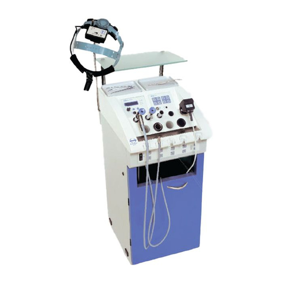
ATMOS Strobo LED
in ATMOS S 61 Servant vision
ATMOS MedizinTechnik
GmbH & Co. KG
ATMOS Cam
Ludwig-Kegel-Straße 16
79853 Lenzkirch/Germany
Tel. +49 7653 689-222
Fax +49 7653 689-292
MedizinTechnik
M531.2010.B
M531.2020.B
M531.2055.B
M531.2065.B
M531.2070.B
M531.2080.B
M531.2090.B
M531.2050.B
service@atmosmed.de
www.atmosmed.de
Advertisement


Need help?
Do you have a question about the Cam and is the answer not in the manual?
Questions and answers