
Related Manuals for Abus AWLX PRO


Summary of Contents for Abus AWLX PRO
- Page 1 Installation instructions and user guide wAppLoxx Pro WLX PRO – Access and Intrusion WLX-PRO-L* – installation instructions and user guide wAppLoxx Pro...
-
Page 2: Table Of Contents
Contents General ............................3 Technical data ..........................5 Installing wAppLoxx Pro Double-Knob Cylinder ................7 III. Individual parts ..........................7 Installation ........................... 9 Installation from the outside ....................9 WLX-PRO-LA ............................ 9 WLX-PRO-HZ (from Step 3) ......................9 2.2 Installation from the inside ..................... 13 Installation: Adjusting the cylinder body to the door thickness .......... -
Page 3: General
Chapter III.3. ABUS Security-Center GmbH & Co. KG shall not be held liable for loss or damage caused – or alleged to have been caused – either directly or indirectly by this manual. We reserve the right to make changes to this manual without prior notice. - Page 4 Information on the battery: The wAppLoxx Pro Cylinder is powered with direct current via a 3 V CR2 lithium battery that is included in the scope of delivery. In order to ensure a long lifespan and to prevent fire and injury, comply with the following instructions: •...
-
Page 5: Technical Data
Double-knob cylinder for doors without PZ perforation Scope of delivery: Locking cylinder, quick guide, forend screw, VARTA 3 V CR2 lithium battery Required accessories: ABUS Mifare DESfire EV1 Tag, WLX Pro Tool Set (small) Optional accessories: WLX card reader WLX Pro tool set (large) - Page 6 Material: Knob: Stainless steel Reading cap: plastic Outer knob colour variants: black, white, grey Delivery status: Coupled (Decoupling is not carried out until it has been successfully programmed into the wAppLoxx Pro Control) Functions: Opening period can be set to 6 or 12 seconds Tag reader Remote access –...
-
Page 7: Installing Wapploxx Pro Double-Knob Cylinder
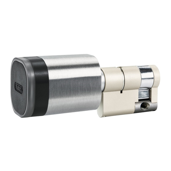
III. Installing wAppLoxx Pro Double-Knob Cylinder 1. Individual parts 11 10 1. Outer cap 2. Battery 3. Electronic knob with 30-mm shaft 3.1. PCB holder 3.2. Basket 3.3. Shaft with motor 4. Mounting plate 5. Outer cylinder body 6. Core retaining ring 7. - Page 8 Tools required (must be ordered separately): a. Closing pliers b. Opening pliers c. 1.5-mm hexagon key, inner knob, WLX Pro d. 2.5-mm hexagon key, modular, WLX Pro e. Outer cap opening key Two different tool sets are available. ACWZ00001 - WLX Pro tool set, large for extensions •...
-
Page 9: Installation
2. Installation 2.1 Installation from the outside WLX-PRO-LA WLX-PRO-HZ (from Step 3) wAppLoxx Pro as delivered Outer cap (1) and inner knob (13) are installed. The battery (2) is not yet inserted. The cam is coupled to prevent accidental locking. Removing the inner knob The inner knob (13) must be removed in order to insert the wAppLoxx Pro into the lock from the outside. - Page 10 Installing the inner knob Screw the inner knob (13) into the thread in the shaft end piece (12) using a 1.5-mm hexagon key (c). Removing the outer cap 1 The outer cap (1) has to be removed in order to insert the battery (2).
- Page 11 Removing the outer cap 3 Once the outer cap (1) has been pulled over the sealing ring, the outer cap can be completely pulled off the knob. Make sure that the outer cap (1) is straight when pulled off. If not, you risk damaging the antenna circuit board. –...
- Page 12 Inserting the battery Make sure that the battery (2) is placed on the white battery flag. When inserting the battery, make sure that the polarity is correct (positive terminal facing antenna circuit board). Installing the outer cap Screw the outer cap (1) back on by securing the mounting plate using the opening key (e).
-
Page 13: Installation From The Inside
2.2 Installation from the inside The cylinder must be installed from the inside for the following variants: • WLX-PRO-LB • WLX-PRO-LA-P • WLX-PRO-LA OPZ wAppLoxx Pro as delivered Outer cap (1) and inner knob (13) are installed. The battery (2) is not yet inserted. The cam (10) is coupled to prevent accidental locking. - Page 14 Installing the basket During installation, make sure that the mounting plate (4) between the basket (3.2) and the shaft with the motor (3.3) is inserted in the correct order. When the cylinder body has been installed in the lock, secure the basket (3.2) to the shaft with the motor (3.3) using 6 screws.
- Page 15 Inserting the battery Make sure that the battery (2) is placed on the white battery flag. When inserting the battery, ensure the polarity is correct (positive terminal facing antenna circuit board). Installing the outer cap Screw the outer cap (1) back on by securing the mounting plate (4) using the opening key (e).
-
Page 16: Installation: Adjusting The Cylinder Body To The Door Thickness
3. Installation: Adjusting the cylinder body to the door thickness 3.1 Extending the inside Removing the core retaining ring Remove the core retaining ring (6) on the outer cylinder body (5) using the WLX Pro opening pliers (a). Removing the shaft Remove the shaft end piece (12) from the outer cylinder body (5) Releasing the cylinder body... - Page 17 Changing the inner extension connector Twist the inner extension connector (8) out of the outer extension connector (11) Changing the inner extension connector Screw the desired inner extension connector (8) into the outer extension connector (11). There is a specific extension connector (30 mm–90 mm) (8) for every inner length.
- Page 18 Securing the shaft Fit a new core retaining ring using the closing pliers to secure the shaft. Make sure that the various shaft extensions interlock and that the corresponding groove is positioned at the opening of the core retaining ring. Make sure that a new core retaining ring (6) is used each time the length is adjusted during installation.
-
Page 19: Extending The Outside
3.2 Extending the outside Removing the core retaining ring Remove the core retaining ring (6) on the outer cylinder body (5) using the WLX Pro opening pliers (a). Removing the shaft Remove the shaft end piece (12) from the outer cylinder body (5) Releasing the cylinder body Remove the grub screw in the outer cylinder body (5) using the hexagon key (d) - Page 20 Changing the outer extension connector Twist the inner extension connector (8) out of the outer extension connector (11). To do this, first remove the core retaining ring on the inside (see above). Screw the inner extension connector into the desired outer extension connector.
- Page 21 Securing the electronic knob with shaft Fit a new core retaining ring (6) using the closing pliers (a) to secure the shaft. Make sure that the various shaft extensions interlock and that the corresponding groove is positioned at the opening of the core retaining ring.
-
Page 22: Logging The Wapploxx Pro Cylinder Into And Out Of The Wapploxx Control
Logging the wAppLoxx Pro Cylinder into and out of the wAppLoxx Control Logging a wAppLoxx Pro Cylinder in: Create a new wAppLoxx Cylinder via the wAppLoxx Control Pro user interface and click on “Register” – for more information, please see the user guide of the wAppLoxx Pro Control. Now hold the wAppLoxx Pro System Card in front of the cylinder to be registered. -
Page 23: Operating The Wapploxx Pro Cylinder
When the cylinder has recognised the reset card, it will flash green briefly. 1 × green Once the cylinder has been successfully logged out, the cylinder will light up green and return to its original 1 × green state. Both cards are included in the scope of delivery of the wAppLoxx Pro Control Operating the wAppLoxx Pro Cylinder A brief green flash signals that the tag is being read and sent. - Page 24 Disarming: 1. Present a valid tag to the reader. 2. After presenting the tag: 1 × green flash. 1 × green 3. Remove tag. The system is coupled for 6 or 12 seconds. The door lock is actuated with the outer knob. Arming: 1.
- Page 25 4. Present the tag to the reader again while coupled and then remove it. 5. The cylinder acknowledges the successful arming process with a red light. 1 × red Using the fallback tag: 1. Present a valid fallback tag to the reader. 2.
- Page 26 Possible acknowledgements of the wAppLoxx Pro Cylinder: Access 2 × green Access denied 3 x red System is armed 1 × red System is disarmed 1 × green Battery Warning 3 × red, 2 × green Authorised fallback transponder was presented 1 ×...
- Page 27 Possible acknowledgements of the wAppLoxx Cylinder login/logout process: Login successful 2 × green Logout successful 3 × red Login failed 1 × red Fallback tag/reset card required to log out 10 × red Possible acknowledgements of the wAppLoxx Cylinder initialisation process: Communication with the outer knob possible 2 ×...
- Page 28 Please contact your dealer or dispose of the products at the local collection point for electronic waste. ABUS Security Center GmbH & Co. KG Linker Kreuthweg 5 86444 Affing If you have any technical questions, please contact your specialist dealer.
Need help?
Do you have a question about the AWLX PRO and is the answer not in the manual?
Questions and answers