Table of Contents
Advertisement
Quick Links
Advertisement
Table of Contents

Subscribe to Our Youtube Channel
Summary of Contents for RNA SCU1000
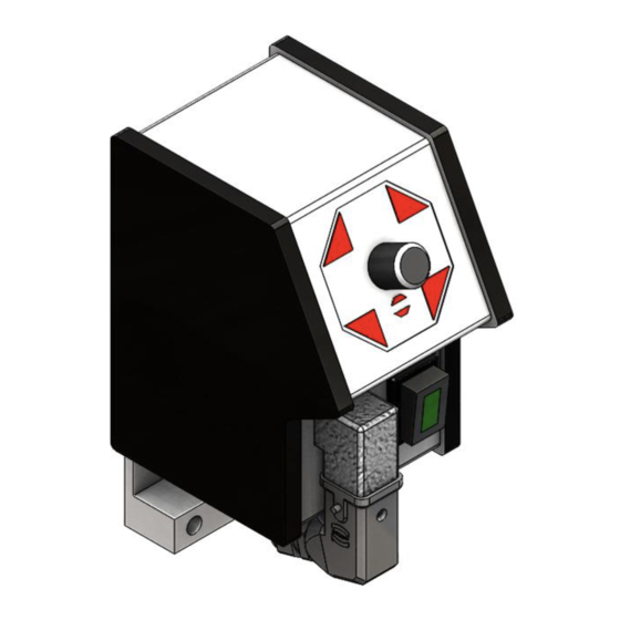
- Page 1 Operating Instructions Controller for vibratory drive systems SCU1000...
-
Page 2: Table Of Contents
Table of Contents Technical data ........................4 1.1. Functional description ......................4 1.2. EC - Conformity ........................4 1.3. Technical data ........................4 Safety notes ........................... 5 Information for starting......................5 3.1. Explanations on the term OPERATING MODE ..............6 3.2. - Page 3 Declaration of Conformity According to the Low-Voltage Directive 2014/35/EU and Electromagnetic Compatibility Directive 2014/30/EU We hereby declare that the product meets the following requirements: Low-Voltage Directive 2014/35/EC Electromagnetic Compatibility Directive 2014/30/EU Applied harmonised standards: DIN EN 60204 T1 EN 61439-1 Remarks: Rhein-Nadel-Automation ---------------------------------...
-
Page 4: Technical Data
Functional description The compact design of the control unit can supply all RNA-control units up to a load current of 6 ampere. It is intended for individual installation directly at the oscillating drive and completely pluggable. The correcting range for the potenti-... -
Page 5: Safety Notes
2. Safety notes The safety notes shall in any case be read and understood. Their observance secures the conservation of valuable material and avoids health impairment. The symbol of the pointing hand is shown in these operating instructions at points, which must be particu- larly observed, so that recommendations, regulations, notes and the correct procedure of work can be ob- served, as well as damage and destruction of the machine and/or other equipment parts is avoided. -
Page 6: Explanations On The Term Operating Mode
3.1. Explanations on the term OPERATING MODE RNA - Oscillating drives are mechanical spring vibrators, which, according to weight and/or size, are adjusted to an oscillating frequency near the mains frequency. Two operating modes are possible: 1. Asymmetrical half-wave operation - the oscillating drive operates with mains frequency. -
Page 7: Setting The Minimum And Maximum Output Voltage
3.3. Setting the minimum and maximum output voltage The control units have been adjusted in the factory at a reference drive. In special cases or after modifications a read- justment may become necessary. Here it must in any case be observed: The output voltage can only be measured with an oscillating drive being connected! The measuring device must be designed for real effective measurement. -
Page 8: Plan Showing The Position Of The Operating Elements On The Boards
4. Plan showing the position of the operating elements on the boards Token Commentasy Switch 110 V – 230 V Electric voltage Release External release External contact External voltage ESG 1000 24 V. DC Potentiometer Pos. 59 10kOhm Electric cable Pos. 80 Electric switch Pos. -
Page 9: Scale Drawing
5. Scale Drawing 6. Connecting Diagram Rhein-Nadel Automation GmbH VT-BA-ESG1000-EN-2020 / 07.10.2020 SJ... - Page 10 Reichsweg 19-23 D-52068 Aachen Phone: +49 (0) 241-5109-0 Fax: +49 (0) 241-5109-219 E-mail: vertrieb@RNA.de Further manufacturing sites www.RNA.de of the RNA Group Further RNA group companies: Manufacturing Lüdenscheid branch Rhein-Nadel Automation GmbH Manufacturing and Sales Nottebohmstraße 57 Focus: Pharmaceutical Industry D-58511 Lüdenscheid...


Need help?
Do you have a question about the SCU1000 and is the answer not in the manual?
Questions and answers