
Subscribe to Our Youtube Channel
Related Manuals for Renishaw PI 7-3


Summary of Contents for Renishaw PI 7-3
- Page 1 PI 7-3 installation guide www.renishaw.com PI 7-3 installation guide Documentation part number: H-1000-7555-02-D Issued 08 2019...
-
Page 2: General Information
Renishaw distributor. Warranty Renishaw plc warrants its equipment for a limited period (as set out in our Standard Terms and Conditions of Sale) provided that it is installed exactly as defined in associated Renishaw documentation. Prior consent must be obtained from Renishaw if non-Renishaw equipment (e.g. interfaces and/or cabling) is to be used or substituted. Failure to comply with this will invalidate the Renishaw warranty. -
Page 3: Care Of Equipment
Renishaw probes and associated systems are precision tools used for obtaining precise measurements and must therefore be treated with care. Changes to Renishaw products Renishaw reserves the right to improve, change or modify its hardware or software without incurring any obligations to make changes to Renishaw equipment previously sold. Packaging... -
Page 4: Product Compliance
Information to user (47 CFR 15.21) The user is cautioned that any changes or modifications not expressly approved by Renishaw plc or authorised representative could void the user's authority to operate the equipment. - Page 5 NOTE: For PI 7-3 controller ratings refer to section 'Power supply'. The PI 7-3 is isolated from ac power by disconnection of the IEC mains connector from the supplied PSU. If any additional means of isolation is required , it must be specified and fitted by the machine manufacturer or installer of the product. The isolator / disconnection device must be sited within easy reach of the operator and comply with any applicable national wiring regulations for the country of installation.
-
Page 6: Environmental Conditions
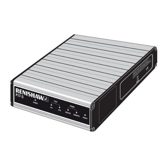
PI 7-3 installation guide www.renishaw.com Environmental conditions The following environmental conditions comply with those defined in BS EN61010-1:2001: Indoor use IP30 (no protection against water) Altitude Up to 2000 m Operating temperature 0 °C to +50 °C Storage temperature ‐10 °C to +70 °C Relative humidity 80 % maximum for temperatures up to +31 °C. - Page 7 PI 7-3 installation guide www.renishaw.com Introduction The PI 7-3 is a dedicated signal conditioner for interfacing the TP7M series of probes or touch-trigger probe types such as TP2, TP20 or TP6 / TP6A, to the CMM controller. PI 7-3 interface unit - A-5726-0100...
-
Page 8: Technical Description
Technical description The PI 7-3 automatically recognises the probe type, determines the probe status, which is either triggered or seated (armed), and transmits debounced signals to the CMM controller. Status and control signals are transferred between the PI 7-3 interface, other Renishaw equipment and the CMM controller via the product interconnection system (PICS) ports.The TP7M probe series employ silicon strain sensors to detect the... -
Page 9: Front Panel Indicators
PDAMP asserted Reset switch Automatically, the probe will reset to the armed state when the PI 7-3 is powered up. Occasionally, it may be necessary to perform a manual reset, for example after changing the probe stylus. Press the RESET button on the front panel for two seconds to reset the probe to the armed (seated) state. -
Page 10: Configuration Switches
PI 7-3 installation guide www.renishaw.com Configuration switches Issued 08 2019... - Page 11 PI 7-3 installation guide www.renishaw.com Switch no. Function Position Description SSR invert SSR closed when probe seated DOWN SSR open when probe seated Buzzer Audible indication of probe trigger - OFF DOWN Audible indication of probe trigger - ON Kinematic probe input...
- Page 12 Switch 3 With switch 3 UP, the PI 7-3 will automatically change operating modes from TP7M to kinematic probe types (TP2, TP20 or TP6 / TP6A) when a TP6A probe or PAA series adapter is attached to the Renishaw autojoint connector on the probe head. Switch 3 should be set to the DOWN position only when it is necessary to connect a kinematic probe or an electronic trigger, from an external source, to the PICS input connector.
-
Page 13: Connector Pins
Set switch 10 UP to operate as the custom product A-1073-0544 which has a modified debounce time. NOTE: All configuration switches are hardware controlled and do not require the PI 7-3 to be switched off and on again to make the selection active. - Page 14 PI 7-3 installation guide www.renishaw.com PICS input connector The PICS input connector is a 9 pin ‘D' type socket. The pin numbers ﴾viewed on the rear panel﴿ are shown in the table below. Pin no. Function Pin no. Function STOP...
- Page 15 PI 7-3 installation guide www.renishaw.com Probe multiwire cable Pin no. Function Pin no. Function REF GAUGE TP2 RETURN GAUGE 1 GAUGE 2 GAUGE 3 TP2 INPUT +5 V HEAD POSITIVE -5 V HEAD LED RETURN PROBE ID Shell SCREEN Dimensions Enclosure style 1/3 rack ﴾19 inch﴿...
- Page 16 PI 7-3 installation guide www.renishaw.com Replacement of PI 7, PI 7c and PI 7H The following table relates the PI 7-3 configuration switches to the previous standard and custom versions of the PI 7. Function PI 7-3 PI 7-2 *...
-
Page 17: Installation Procedure
The interconnections for the TP7 system on a PH10M motorised probe head are shown in the following illustrations. NOTE: The first illustration refers to the external PI 7-3 unit and the second showns information regarding the integral card version of the product. The table gives a list of alternative standard Renishaw cable lengths and part numbers. - Page 18 PI 7-3 installation guide www.renishaw.com Issued 08 2019...
- Page 19 PI 7-3 installation guide www.renishaw.com Cable no. PL no. Length (m) Part number Notes 0.4 to 0.8 A-1016-7672 Coiled 0.8 to 1.6 A-1016-7673 Coiled PL12 A-1016-7674 Plain PL13 0.1 to 0.2 A-1016-7675 Coiled PLM6 A-1016-7564 Unterminated PLM7 A-1016-7563 Unterminated PLM8...
- Page 20 Insert the PI 7-3 card, ensuring that the card is located in the correct grooves shown in the following illustration Insert the reset actuator over the top of the reset button on the PI 7-3 card and then replace the end panel...
- Page 21 PI 7-3 installation guide www.renishaw.com Issued 08 2019...
-
Page 22: Maintenance
Check the security of mounting screws and electrical connectors Remove dust from the external surfaces with a proprietary cleaning cloth There are no user serviceable parts within the PI 7-3 Renishaw recommends regular CMM calibration to ensure optimum metrology performance... -
Page 23: Power Supply
Powering the PI 7-3 The PI 7-3 TP7 interface is to be used with the provided PSU - Emerson DP4024N3M ac power adaptor (www.emerson.com). This is a 24 Vdc 49 W supply and is connected to the PI 7‐3 via Ø5.5 mm dc jack plug. - Page 24 Renishaw plc +44 (0)1453 524524 New Mills, Wotton-under-Edge, +44 (0)1453 524901 Gloucestershire, GL12 8JR United Kingdom www.renishaw.com/cmmsupport For worldwide contact details, please visit our main website at www.renishaw.com/contact Issued 08 2019...
Need help?
Do you have a question about the PI 7-3 and is the answer not in the manual?
Questions and answers