Table of Contents
Advertisement
Advertisement
Table of Contents

Related Manuals for Renishaw HSI


Summary of Contents for Renishaw HSI
- Page 1 Installation guide H-5500-8554-04-A HSI hard-wired system interface...
- Page 2 This document may not be copied or reproduced in whole or in part, or transferred to any other media or language, by any means, without the prior written permission of Renishaw. The publication of material within this document does not imply freedom from the patent rights of Renishaw plc.
-
Page 3: Table Of Contents
12 V to 30 V M-code connected directly to the HSI ...... - Page 4 HSI installation guide General information ............5.1 Disclaimer .
-
Page 5: Safety
Information to the equipment installer All Renishaw equipment is designed to comply with the relevant EU and FCC regulatory requirements. It is the responsibility of the equipment installer to ensure that the following guidelines are adhered to, in order for the product to function in accordance with these regulations: •... - Page 6 HSI installation guide This page is intentionally left blank.
-
Page 7: Hsi Basics
HSI can draw its power from the machine’s nominal 12 Vdc to 30 Vdc supply. Where such a supply is not available, the HSI can be powered using any 12 Vdc to 30 Vdc (minimum 0.5 A) power supply. -
Page 8: Hsi Components
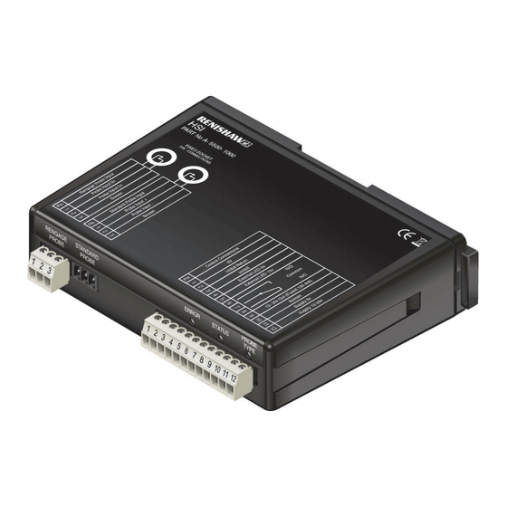
HSI installation guide HSI components The following components are housed within the front face of the HSI (as shown in the figure below): • RENGAGE probe connector block (3-way); • Standard probe connector block (3-way); • Control connector block (12-way);... -
Page 9: Rengage™ Probe Connector (3-Way)
Terminals 4 and 5 If the HSI is installed where it cannot be easily seen, an output is provided so that a remote device (such as an LED or buzzer – not supplied) can be connected to the HSI and positioned near to the machine operator. -
Page 10: Status Led
• a flashing red when a probe inhibit function is active. If the LED is unlit, then there is no power supply to the HSI. Remote device The remote device circuit provides: •... -
Page 11: Solid-State Relay (Ssr)
Maximum voltage is 30 V. NOTE: Change of state debounce time is 25 ms ±5 ms. Debounce time is the time delay between the HSI responding to a probe trigger and the point at which the probe can be used again. Stylus contact bounce... -
Page 12: Probe Inhibit Function
12 V and 30 V to pin 3 (INHIBIT) on the HSI 12-way connector. To deactivate the inhibit function, the 12 V to 30 V supply must be removed from pin 3 (INHIBIT) of the HSI 12-way connector. CNC CONTROLLER... -
Page 13: M-Code Driven Relay Contact
When using this method, it is recommended that the HSI is connected as shown in the following diagram. Shorting together pin 1 (0 V) and pin 2 (INHIBIT RETURN) of the HSI 12-way connector (less than 100 Ω) will force the output into a seated state, irrespective of actual probe status, and remove power from the probe. -
Page 14: Hsi Dimensions
HSI installation guide HSI dimensions Dimensions given in mm (in) -
Page 15: Hsi Specification
HSI specification Principal application The HSI processes signals from RENGAGE probes or standard probes and converts them into voltage-free SSR output, which is then transmitted to the CNC machine controller. Dimensions Width: 134 mm (5.28 in) Height: 34.7 mm (1.37 in) Depth: 98 mm (3.86 in) - Page 16 HSI installation guide 2.10 This page is intentionally left blank.
-
Page 17: System Installation
HSI with the HSI MP250 TS27R NOTE: Only one probe can be TS34 connected at a time. TS20 NOTE: The connection between the probe socket and the HSI interface must be screened and connected to ground at the interface. -
Page 18: Mounting The Hsi To A Din Rail
HSI installation guide Mounting the HSI to a DIN rail 34.7 (1.37) (5.28) (3.86) Standard DIN rail mounting M4 (× 2) Alternative mounting Dimensions given in mm (in) -
Page 19: Connecting The Hsi To A Rengage™ Probe And The Cnc Controller
Connecting the HSI to a RENGAGE™ probe and the CNC controller For further information on RENGAGE™ probes compatible with HSI, refer to page 3.1. RENGAGE probe connector (3-way) Inner spring pin, Blue 1 Probe input 0 V Outer spring pin, Green... -
Page 20: Connecting The Hsi To A Standard Probe And The Cnc Controller
HSI installation guide Connecting the HSI to a standard probe and the CNC controller For further information on standard probes compatible with HSI, refer to page 3.1. Standard probe connector (3-way) Inner spring pin 1 Probe input + Outer spring pin 2 Probe input −... -
Page 21: Parts List
Parts list Type Part number Description Interface A-5500-1000 HSI probe system interface with DIN rail mounting and three terminal blocks, quick-start guide and packaging. Terminal block P-CN25-0008 3-way terminal block. Terminal block P-CN47-0032 12-way terminal block. Publications. These can be downloaded from our website at www.renishaw.com. - Page 22 HSI installation guide This page is intentionally left blank.
-
Page 23: General Information
HOWSOEVER ARISING, FOR ANY INACCURACIES IN THIS DOCUMENT. Trade marks RENISHAW and the probe symbol used in the RENISHAW logo are registered trade marks of Renishaw plc in the United Kingdom and other countries. apply innovation and names and designations of other Renishaw products and technologies are trade marks of Renishaw plc or its subsidiaries. -
Page 24: Cnc Machines
Care of the interface Keep system components clean. Patents Features of the HSI, and other similar Renishaw products, are the subject of one or more of the following patents and/or patent applications: EP 1425550 EP 1804020 JP 4237051... -
Page 25: Reach Regulation
This device must accept any interference received, including interference that may cause undesired operation. 47 CFR Section 15.21 The user is cautioned that any changes or modifications not expressly approved by Renishaw plc or authorised representative could void the user’s authority to operate the equipment. 47 CFR Section 15.105 This equipment has been tested and found to comply with the limits for a Class A digital device, pursuant to part 15 of the FCC Rules. - Page 26 Renishaw plc +44 (0)1453 524524 +44 (0)1453 524901 New Mills, Wotton-under-Edge uk@renishaw.com Gloucestershire, GL12 8JR United Kingdom www.renishaw.com For worldwide contact details, visit www.renishaw.com/contact *H-5500-8554-04* Issued: 01.2020 Part no. H-5500-8554-04-A © 2008–2020 Renishaw plc...
Need help?
Do you have a question about the HSI and is the answer not in the manual?
Questions and answers