Table of Contents
Advertisement
Advertisement
Table of Contents

Related Manuals for SICK CFP CUBIC


Summary of Contents for SICK CFP CUBIC
- Page 1 O P E R A T I N G I N S T R U C T I O N S CFP CUBIC Level sensor...
- Page 2 79183 Waldkirch Germany Legal notes This work is protected by copyright. The associated rights are reserved by SICK AG. Reproduction of this document or parts of this document is only permissible within the limits of the legal provisions of copyright law.
-
Page 3: Table Of Contents
Pin assignment, M12 plug connector, 8-pin ......... 17 8021989 / 2017-10-20 | SICK AG O P E R A T I N G I N S T R U C T I O N S | C F P C U B I C... - Page 4 O P E R A T I N G I N S T R U C T I O N S | C F P C U B I C 8021989 / 2017-10-20 | SICK AG Subject to change without notice...
- Page 5 Factory setting ....................53 Accessories ....................54 8021989 / 2017-10-20 | SICK AG O P E R A T I N G I N S T R U C T I O N S | C F P C U B I C...
-
Page 6: About This Document
O P E R A T I N G I N S T R U C T I O N S | C F P C U B I C 8021989 / 2017-10-20 | SICK AG Subject to change without notice... -
Page 7: Further Information
8021989 / 2017-10-20 | SICK AG O P E R A T I N G I N S T R U C T I O N S | C F P C U B I C... -
Page 8: Safety Information
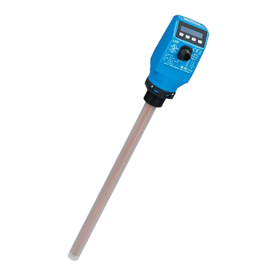
Safety information Intended use The CFP Cubic is a level sensor based on a capacitive measurement principle. The level is determined and the limit values are assessed by evaluating the capacitive fields. The sensor is designed for both continuous level measurement and discontinuous level measurement in nearly all liquids. -
Page 9: Requirements For Skilled Persons And Operating Personnel
8021989 / 2017-10-20 | SICK AG O P E R A T I N G I N S T R U C T I O N S | C F P C U B I C... -
Page 10: General Safety Notes
Repairs Repair work on the sensor may only be performed by qualified and authorized personnel from SICK AG. Interference with or modifications to the sensor on the part of the cus- tomer will invalidate any warranty claims against SICK AG. -
Page 11: Product Description
3.1.2 Type code 0100 – Cubic Position Description Product group CFP Cubic: Capacitive level sensor CFP Cubic Probe length in mm 0100: 100 mm ascending in increments of 100 mm 1,000: 1,000 mm Certification Without certification Probe design PP rod probe... -
Page 12: Product Characteristics
3.3.1 Principle of operation The CFP Cubic works according to the capacitive measurement principle. This means that electrodes are integrated in the probe to span and measure a capacitive field. The medium touching the probe influences the measured capacitance. Linear to the level, this change in capacitance is then evaluated in the sensor and output as a corre- sponding level. -
Page 13: Transport And Storage
8021989 / 2017-10-20 | SICK AG O P E R A T I N G I N S T R U C T I O N S | C F P C U B I C... -
Page 14: Mounting
A minimum connecting piece diameter in accordance with the following graphic must be observed. The CFP Cubic is to be installed in such a way that, after it has been mounted, there is a sufficient distance between it and other tank components (e.g., supply pipes, other measuring devices) as well as the sides and bottom of the con- tainer. -
Page 15: Electrical Installation
If this is not done, the device does not fulfill any specified IP enclosure rating! 8021989 / 2017-10-20 | SICK AG O P E R A T I N G I N S T R U C T I O N S | C F P C U B I C... -
Page 16: Electrical Connection
O P E R A T I N G I N S T R U C T I O N S | C F P C U B I C 8021989 / 2017-10-20 | SICK AG Subject to change without notice... -
Page 17: Pin Assignment, M12 Plug Connector, 8-Pin
The wire colors for 8-pin cables are not uniform. Always note the pin assignment of the sensor. 8021989 / 2017-10-20 | SICK AG O P E R A T I N G I N S T R U C T I O N S | C F P C U B I C... -
Page 18: Commissioning
O P E R A T I N G I N S T R U C T I O N S | C F P C U B I C 8021989 / 2017-10-20 | SICK AG Subject to change without notice... - Page 19 “11 Troubleshooting”. 8021989 / 2017-10-20 | SICK AG O P E R A T I N G I N S T R U C T I O N S | C F P C U B I C Subject to change without notice...
-
Page 20: Operation
O P E R A T I N G I N S T R U C T I O N S | C F P C U B I C 8021989 / 2017-10-20 | SICK AG Subject to change without notice... -
Page 21: Exprt Mode
8021989 / 2017-10-20 | SICK AG O P E R A T I N G I N S T R U C T I O N S | C F P C U B I C Subject to change without notice... -
Page 22: Normally Open With Configurable Hysteresis
O P E R A T I N G I N S T R U C T I O N S | C F P C U B I C 8021989 / 2017-10-20 | SICK AG Subject to change without notice... -
Page 23: Normally Closed With Configurable Hysteresis
Set the parameter to NC in the Q1-### / POL1 menu. 8021989 / 2017-10-20 | SICK AG O P E R A T I N G I N S T R U C T I O N S | C F P C U B I C... -
Page 24: Normally Open With Window Function
O P E R A T I N G I N S T R U C T I O N S | C F P C U B I C 8021989 / 2017-10-20 | SICK AG Subject to change without notice... -
Page 25: Normally Closed With Window Function
The critical filling level for the application is outside the FHx and FLx window thresholds. 8021989 / 2017-10-20 | SICK AG O P E R A T I N G I N S T R U C T I O N S | C F P C U B I C... - Page 26 O P E R A T I N G I N S T R U C T I O N S | C F P C U B I C 8021989 / 2017-10-20 | SICK AG Subject to change without notice...
-
Page 27: Normally Open With Error Signal
8.3.6 Normally open with error signal Application If there is an error message on the CFP Cubic, this can be output using a switching output. Configuration Configure the Qx switching output as normally open for error signals (using Q1 as an example). -
Page 28: Configuration Of Analog Outputs
Set the parameter to NO (normally open) in the Q1-INP / POL1 menu. Configuration of analog outputs 8.4.1 Automatic signal detection The CFP Cubic can automatically detect if a 4–20 mA or 0–10 V signal is required using the connected output load. The following rules apply: •... -
Page 29: Current Output 4 To 20 Ma
Normal = Analog output signal as configured 8021989 / 2017-10-20 | SICK AG O P E R A T I N G I N S T R U C T I O N S | C F P C U B I C... -
Page 30: Behavior Of Outputs In The Event Of An Error
O P E R A T I N G I N S T R U C T I O N S | C F P C U B I C 8021989 / 2017-10-20 | SICK AG Subject to change without notice... -
Page 31: Autocalibration
Via the display by pressing the Set pushbutton for at least 10 seconds 8021989 / 2017-10-20 | SICK AG O P E R A T I N G I N S T R U C T I O N S | C F P C U B I C... -
Page 32: Locking The Display With A Password
O P E R A T I N G I N S T R U C T I O N S | C F P C U B I C 8021989 / 2017-10-20 | SICK AG Subject to change without notice... - Page 33 All parameters and outputs are then set according to the simulated level. 8021989 / 2017-10-20 | SICK AG O P E R A T I N G I N S T R U C T I O N S | C F P C U B I C...
-
Page 34: Evaluating Signal Quality
O P E R A T I N G I N S T R U C T I O N S | C F P C U B I C 8021989 / 2017-10-20 | SICK AG Subject to change without notice... -
Page 35: Setting The Offset
All parameters related to the level (e.g., SP/RP) are adapted according to the offset setting. 8021989 / 2017-10-20 | SICK AG O P E R A T I N G I N S T R U C T I O N S | C F P C U B I C... -
Page 36: Resetting The Calibration
O P E R A T I N G I N S T R U C T I O N S | C F P C U B I C 8021989 / 2017-10-20 | SICK AG Subject to change without notice... -
Page 37: Menu Overview
RstFac Passwd 8021989 / 2017-10-20 | SICK AG O P E R A T I N G I N S T R U C T I O N S | C F P C U B I C Subject to change without notice... -
Page 38: Exprt Mode
O P E R A T I N G I N S T R U C T I O N S | C F P C U B I C 8021989 / 2017-10-20 | SICK AG Subject to change without notice... - Page 39 Off, 3.5...21.5 mA Off, 0...10 V 8021989 / 2017-10-20 | SICK AG O P E R A T I N G I N S T R U C T I O N S | C F P C U B I C...
- Page 40 O P E R A T I N G I N S T R U C T I O N S | C F P C U B I C 8021989 / 2017-10-20 | SICK AG Subject to change without notice...
-
Page 41: Overview Of Parameters
4 to 20 mA, 0 to 10 V or automated. 8021989 / 2017-10-20 | SICK AG O P E R A T I N G I N S T R U C T I O N S | C F P C U B I C... - Page 42 O P E R A T I N G I N S T R U C T I O N S | C F P C U B I C 8021989 / 2017-10-20 | SICK AG Subject to change without notice...
- Page 43 Passwd Currently no function. 8021989 / 2017-10-20 | SICK AG O P E R A T I N G I N S T R U C T I O N S | C F P C U B I C...
-
Page 44: Troubleshooting
O P E R A T I N G I N S T R U C T I O N S | C F P C U B I C 8021989 / 2017-10-20 | SICK AG Subject to change without notice... -
Page 45: Operating The Display
8021989 / 2017-10-20 | SICK AG O P E R A T I N G I N S T R U C T I O N S | C F P C U B I C Subject to change without notice... - Page 46 O P E R A T I N G I N S T R U C T I O N S | C F P C U B I C 8021989 / 2017-10-20 | SICK AG Subject to change without notice...
-
Page 47: Repair
REPAIR Repair 12.1 Maintenance The CFP Cubic is maintenance-free. We recommend that you perform the following measures at regular intervals: − Check the probe for contamination − Check the screw connections and plug connectors 12.2 Returns Rinse off and/or clean removed devices before returning them in order to protect our employees and the environment from dangers posed by residue from measured mate- rials. -
Page 48: Disposal
O P E R A T I N G I N S T R U C T I O N S | C F P C U B I C 8021989 / 2017-10-20 | SICK AG Subject to change without notice... -
Page 49: Technical Data
With water or oil under reference conditions. 8021989 / 2017-10-20 | SICK AG O P E R A T I N G I N S T R U C T I O N S | C F P C U B I C... -
Page 50: Mechanics/Materials
O P E R A T I N G I N S T R U C T I O N S | C F P C U B I C 8021989 / 2017-10-20 | SICK AG Subject to change without notice... -
Page 51: Electrical Connections
All connections are reverse polarity protected. All outputs are overload and short-circuit protected. 8021989 / 2017-10-20 | SICK AG O P E R A T I N G I N S T R U C T I O N S | C F P C U B I C... -
Page 52: Dimensional Drawings
O P E R A T I N G I N S T R U C T I O N S | C F P C U B I C 8021989 / 2017-10-20 | SICK AG Subject to change without notice... -
Page 53: Factory Setting
Lock Inactive 8021989 / 2017-10-20 | SICK AG O P E R A T I N G I N S T R U C T I O N S | C F P C U B I C Subject to change without notice... -
Page 54: Accessories
O P E R A T I N G I N S T R U C T I O N S | C F P C U B I C 8021989 / 2017-10-20 | SICK AG Subject to change without notice... - Page 55 8021989 / 2017-10-20 | SICK AG O P E R A T I N G I N S T R U C T I O N S | C F P C U B I C Subject to change without notice...
- Page 56 Phone +36 1 371 2680 Phone +386 591 788 49 E-Mail office@sick.hu E-Mail office@sick.si India South Africa Phone +91 22 6119 8900 Phone +27 11 472 3733 Further locations at www.sick.com E-Mail info@sick-india.com E-Mail info@sickautomation.co.za SICK AG | Waldkirch | Germany | www.sick.com...
Need help?
Do you have a question about the CFP CUBIC and is the answer not in the manual?
Questions and answers