Table of Contents
Advertisement
Quick Links
Advertisement
Table of Contents

Related Manuals for Eaton Moeller SmartWire-Darwin Series


Summary of Contents for Eaton Moeller SmartWire-Darwin Series
- Page 1 SmartWire-Darwin Gateways Hardware and Engineering 02/09 AWB2723-1612en...
- Page 2 All brand and product names are trademarks or registered trademarks of the owner concerned. published 2009, edition date 02/09 © 2009 by Moeller GmbH, 53105 Bonn Author: Heribert Einwag Editor: René Wiegand Translator: globaldocs GmbH All rights reserved, including those of the translation. No part of this manual may be reproduced in any form (printed, photocopy, microfilm or any other process) or processed, duplicated or distributed by means of electronic...
- Page 3 Danger! Dangerous electrical voltage! Before commencing the installation • Disconnect the power supply of the device. • Suitable safety hardware and software measures should be implemented for the • Ensure that devices cannot be accidentally I/O interface so that a line or wire breakage restarted.
- Page 4 • Measures should be taken to ensure the • Wherever faults in the automation system proper restart of programs interrupted may cause damage to persons or property, after a voltage dip or failure. This should external measures must be implemented to not cause dangerous operating states even ensure a safe operating state in the event for a short time.
-
Page 5: Table Of Contents
02/09 AWB2723-1612en Contents About this Manual Overview SmartWire Darwin Additional device manuals Target group Reading conventions PROFIBUS Gateway EU5C-SWD-DP Introduction Layout Engineering – Connection – PROFIBUS address setting – PROFIBUS connection – Baud Rates – Programming system Installation Mounting – Potential Relationship between the Components 15 –... - Page 6 02/09 AWB2723-1612en Contents Programming Introduction easySoft-CoDeSys – Configuration and parameterization – Selection of the SmartWire Darwin slave – parametric programming – Setting specific parameters of SmartWire Darwin slaves Input/output addresses – Diagnostics EU5C-SWD-CAN Introduction Layout Engineering – Connection – CANopen address setting –...
- Page 7 02/09 AWB2723-1612en Contents Programming Introduction easySoft-CoDeSys – Configuration and parameterization – Selecting the SmartWire Darwin slave – Parametric programming – Guarding mechanisms – Parameters of individual SmartWire Darwin slaves Input/output addresses – Diagnostics – PDO communication Object list – Static entries –...
- Page 8 02/09 AWB2723-1612en...
-
Page 9: About This Manual
02/09 AWB2723-1612en About this Manual Overview SmartWire The SmartWire-Darwin system makes normal Darwin electromechanical switching devices, command devices and signalling devices capable of communication. To achieve this, intelligent add-on components are added to the devices that make possible connection to the communication system SmartWire-Darwin. -
Page 10: Target Group
02/09 AWB2723-1612en About this Manual Target group This manual is intended for automation technicians and engineers. Detailed knowledge of the field bus used is presumed. In addition you should be familiar with the handling of the SmartWire Darwin system. Reading conventions Symbols used in this manual have the following meanings: Indicates instructions to be followed. -
Page 11: Profibus Gateway Eu5C-Swd-Dp
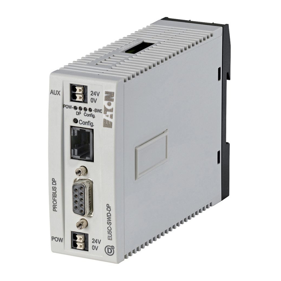
02/09 AWB2723-1612en PROFIBUS Gateway EU5C-SWD-DP Introduction The SmartWire-Darwin gateway EU5C-SWD-DP creates a connection between the SmartWire-Darwin slaves and an overriding PROFIBUS-DP master. Layout Figure 1: Front view EU5C-SWD-DP a 24-V power supply POW b Field bus interface c Diagnostics interface d Configuration button e Diagnostics displays f 24-V power supply AUX... -
Page 12: Engineering
02/09 AWB2723-1612en PROFIBUS Gateway EU5C- SWD-DP The SmartWire Darwin ribbon cable is connected to the slaves at the gateway. Connection to the PROFIBUS field bus is effected via the standardized 9-pole PROFIBUS plug. In addition terminals for two power supplies are available, one for the SmartWire Darwin slaves and another 24 volts for supply of the contactor coils in case these are also operated via SmartWire Darwin slaves. -
Page 13: Connection
02/09 AWB2723-1612en Engineering Connection 24 V DC Figure 2: Connection Power supply of the gateway and supply of the SmartWire- Darwin slave electronics are performed via the terminals POW. The gateway contains an additional power supply unit for the 15 V supply of the SmartWire-Darwin slaves with an amperage of 0.7 A. - Page 14 02/09 AWB2723-1612en PROFIBUS Gateway EU5C- SWD-DP – Miniature circuit-breaker 24 V DC rated operational current 2 A; tripping characteristics C or – Fuse 2 A • Miniature circuit-breaker 24 V DC for AUX – Line protection in accordance with DIN VDE 0641 Part 11, IEC/EN 60898: –...
-
Page 15: Profibus Address Setting
02/09 AWB2723-1612en Engineering In the planning of the SmartWire Darwin network you are also supported by the software program SmartWire- Darwin-Assist, which automatically draws your attention to the use of any necessary new feeder modules. PROFIBUS address setting The coupling unit requires a unique PROFIBUS-DP slave address in the PROFIBUS network. -
Page 16: Programming System
02/09 AWB2723-1612en PROFIBUS profile The device supports the PROFIBUS V0 profile. Programming system A device master file (GSD file) is necessary for selection of the device and operation via the field bus PROFIBUS-DP. The GSD file contains standardized descriptions of the PROFIBUS slaves. -
Page 17: Installation
02/09 AWB2723-1612en Installation Mounting Please proceed as follows to install the device: First of all set the PROFIBUS slave address. This is set on the gateway via DIP switches (switches 2 - 8). The DIP switches are located under a cover on the right side of the gateway. - Page 18 02/09 AWB2723-1612en Installation Figure 5: Mounting on top-hat rail Connect the 24 V DC voltage to the terminals POW on the front side of the gateway. If necessary, connect the 24 V DC voltage for the contactor coils to the terminals AUX. Warning! In safety-related applications the power supply unit that supplies the SmartWire Darwin system must be executed...
-
Page 19: Potential Relationship Between The Components
02/09 AWB2723-1612en Mounting Warning! Switch off the power supply, if you are reconnecting slaves in the SmartWire-Darwin system or reconnecting the ribbon cable connection. Otherwise the SmartWire- Darwin slaves can be destroyed! Potential Relationship between the Components The entire SmartWire-Darwin system operates on a common supply voltage. -
Page 20: Profibus-Dp Connection
02/09 AWB2723-1612en Installation SWD4…LF… SWD4-8MF2 Figure 6: Connection via the SmartWire Darwin cable PROFIBUS-DP connection To attach the PROFIBUS-DP cable, a special PROFIBUS-DP plug (e.g. ZB4-209-DS2) is needed. This has the necessary wiring for fault-free operation at up to 12 Mbits/sec. Connect the PROFIBUS-DP cable by means of the PROFIBUS-DP plug to the field bus interface of the gateway. -
Page 21: Emc-Conformant Wiring Of The Network
02/09 AWB2723-1612en EMC-conformant wiring of the network Figure 7: Connection for PROFIBUS-DP EMC-conformant wiring of Undesired faults can occur on the field bus due to the network electromagnetic interference. This can be minimised beforehand by the implementation of suitable EMC measures. - Page 22 02/09 AWB2723-1612en Installation for top-hat rail for mounting plate ZB4-102-KS1 ZB4-102-KS1 KLBü 3-8 SC FM 4/TS 35 (Weidmüller) (Weidmüller) Figure 8: Shielding of network cable...
-
Page 23: Commissioning
02/09 AWB2723-1612en Commissioning Before switching on, check whether the power supply for the gateway is connected correctly . The configuration and installation of the Smart Wire Darwin network must also have been carried out correctly (with all slaves connected). If you have already integrated devices into a system, secure any parts of the system connected to the working area to prevent access and ensure that no-one can be injured if, for example, motors start up unexpectedly. - Page 24 02/09 AWB2723-1612en Commissioning Warning! If a SmartWire-Darwin slave has failed, the SmartWire- Darwin network can still be operated with the remaining slaves, depending on the configuration setting (even after a repeat power up of the gateway). The failure is reported to the application.
- Page 25 02/09 AWB2723-1612en Putting the SmartWire Darwin network into operation Switching on when the gateway target configuration is stored If a configuration is stored in the gateway, each time the supply voltage is switched on it is checked whether the slaves actually found on the network comply with the stored gateway target configuration.
-
Page 26: Creating Field Bus Communication
02/09 AWB2723-1612en Commissioning Creating field bus communication If a data interchange is possible between the SmartWire- Darwin slaves and the gateway, in principle communication between the gateway and the controller can also be performed via PROFIBUS. Connect the PROFIBUS gateway to the field bus. Load the program into the controller. - Page 27 02/09 AWB2723-1612en Putting the SmartWire Darwin network into operation So the prerequisite for data interchange is that the configuration drawn up on the PLC system (= planned configuration) complies with the configuration actually available on the gateway. The result of this check is signalled on the gateway via the SmartWire Darwin configuration LED.
- Page 28 02/09 AWB2723-1612en...
-
Page 29: Programming
02/09 AWB2723-1612en Programming Introduction The SmartWire-Darwin gateway is integrated into the PROFIBUS configurator of the programming system as a DP slave. A device master file (GSD file) which contains a standardized description of the SmartWire-Darwin gateway is necessary for this. Depending on the PROFIBUS master used two different versions are available for this: •... -
Page 30: Easysoft-Codesys
02/09 AWB2723-1612en Programming easySoft-CoDeSys Configuration and parameterization The connection of a SmartWire-Darwin network via the gateway EU5C-SWD-DP to the controller XC200 is described in this section. Please check beforehand whether you have a current easySoft-CoDeSys version installed with the necessary GSD files. Then please proceed as follows: Start easySoft-CoDeSys and open a project. -
Page 31: Selection Of The Smartwire Darwin Slave
02/09 AWB2723-1612en easySoft-CoDeSys Mark the DP master module and via the menu option Insert -> Attach sub-element open die selection list for the DP slave modules. Select the gateway EU5C-SWD-DP (int) (Moe4d13.gsd). Figure 10: Selection of the gateways Selection of the SmartWire Darwin slave Change over to the register Inputs/Outputs. -
Page 32: Parametric Programming
02/09 AWB2723-1612en Programming Figure 11: Selection of the slaves parametric programming Parameters for communication of the gateway with the PROFIBUS master and with the SmartWire-Darwin network are also defined in the controller configuration. The meaning of the individual registers: “Basic Parameters” register You can define here the I/O start addresses for the mapping of the SmartWire-Darwin slaves onto the inputs/outputs of the controller map. - Page 33 02/09 AWB2723-1612en easySoft-CoDeSys Register “DP Parameters” The parameters that relate to communication with the field bus PROFIBUS-DP are entered under these settings. These include, for example, the DP-slave address (node ID) or the monitoring time (watchdog control). Figure 12: Setting the DP parameters Register “Application Parameters”...
- Page 34 02/09 AWB2723-1612en Programming Table 3: Application parameters Mode parameter Value Meaning SmartWire Darwin baud 125 kBit/s The baud rate of the SmartWire Darwin rate network. The value is a fixed setting and can not be changed. Compatible devices The planned slaves in the PROFIBUS allowed configuration must comply with the slaves of the stored gateway target configuration.
-
Page 35: Setting Specific Parameters Of Smartwire Darwin Slaves
02/09 AWB2723-1612en easySoft-CoDeSys Setting specific parameters of SmartWire Darwin slaves You can parameterize the transient behaviour for each SmartWire-Darwin slave. By doing this you define how the gateway reacts, if a slave is not available. The standard setting is that all slaves have to be available. However, the information as to whether a slave is available is also reported to the application via the diagnosis so that the failure of a slave can be reacted to individually here... -
Page 36: Input/Output Addresses
02/09 AWB2723-1612en Programming Figure 13: Parameterizing SWD slaves (= module) Parameter setting at this point only makes sense if the value Defined for each slave is set in the application parameters for the parameter All Slaves optional. Input/output addresses With the configuration of the SmartWire-Darwin slaves in the controller configurator the input/output addresses of the slaves are assigned automatically. - Page 37 02/09 AWB2723-1612en Input/output addresses Figure 14: SWD slave addresses The inputs and, if necessary, the outputs are used as “normal” local inputs/outputs in the application program. Please refer to the manual AWB2723-1613 for the assignment and meaning of the input and output data.
-
Page 38: Diagnostics
02/09 AWB2723-1612en Programming Diagnostics Please refer to the documentation of the PROFIBUS-DP master XIOC-NET-DP-M in the manual AWB2725-1452 for basic information on the DP diagnostics. You will find explanations there on access to the diagnostic data of a DP slave station. The system SmartWire Darwin provides you with cyclic and acyclic diagnostic information. - Page 39 02/09 AWB2723-1612en Input/output addresses Designation Meaning NC1 = Normally Close 0: contact actuated 1: contact not actuated NO = Normally Open 0: contact not actuated 1: contact actuated not used not used F = Failure 0: No diagnostic alarm 1: Diagnostics available not used P = modules present 0: Modules not available...
- Page 40 02/09 AWB2723-1612en Programming In the case of the SmartWire-Darwin slave considered here the following detailed conditions could be determined. Value Meaning 0x10 The contact is longer than four seconds in the middle position. 0x11 There is a short circuit in the contact. Acyclic diagnostics As could already be seen in the configuration, the SmartWire-Darwin gateway with its slaves appears as a...
- Page 41 02/09 AWB2723-1612en Input/output addresses Standard diagnosis header DP-V0 header structure Byte Value Explanation V0 Status-1 V0-Status-2 V0-Status 3 DP master address 0x4d Moeller device identification: 0x13 Moeller device identification: Please refer to the documentation of the PROFIBUS-DP master XIOC-NET-DP-M in the document AWB2725-1425 for the meanings of the status bytes.
- Page 42 02/09 AWB2723-1612en Programming Byte Value Description Module status Two status bits for SWD slaves 1 - 4 … Two status bits for SWD slaves 5 - 8 Two status bits for other SWD slaves In the first byte the module status block contains the length of the complete module status block, followed by the codes 0x82, 0x00, 0x00.
- Page 43 02/09 AWB2723-1612en Input/output addresses Table 4: Structure of the extended diagnosis Byte Value Description Length of detailed status message 0xA1 Status type SmartWire Darwin slave address (1 - 58) first detailed diagnostic message/status message nth detailed diagnostic message/status message Example A SmartWire-Darwin network consists of nine SmartWire- Darwin slaves.
- Page 44 02/09 AWB2723-1612en Programming Absolute Byte Value Description byte 0x01 The SmartWire Darwin slave 5 reports a diagnosis. The SmartWire Darwin slave 9 does not report a diagnosis. Extended diagnostics E/A module Length of detailed status message 0xA1 Status type SmartWire-Darwin slave address 0x13 Message: short-circuit/overload...
-
Page 45: Eu5C-Swd-Can
02/09 AWB2723-1612en EU5C-SWD-CAN Introduction The SmartWire-Darwin gateway EU5C-SWD-CAN creates a connection between the SmartWire-Darwin slaves and an overriding CANopen master. Layout Figure 15: Front view EU5C-SWD-CAN a 24-V power supply POW b Field bus interface c Diagnostics interface d Configuration button e Diagnostics displays f 24-V power supply AUX g Connection SmartWire-Darwin... -
Page 46: Engineering
02/09 AWB2723-1612en EU5C-SWD-CAN The gateway creates a connection between the slaves on the SmartWire-Darwin network and the overriding PLC. Furthermore, it provides two power supplies, one for the SmartWire-Darwin slaves and a 24 power supply for the contactor coils, in case this is also operated via a SmartWire- Darwin slave. -
Page 47: Connection
02/09 AWB2723-1612en Engineering Connection 24 V DC Figure 16: Connection Power supply of the gateway and supply of the SmartWire- Darwin slave electronics are performed via the terminals POW. The gateway contains an additional power supply unit for the 15 V supply of the SmartWire-Darwin slaves with an amperage of 0.7 A. - Page 48 02/09 AWB2723-1612en – Miniature circuit-breaker 24 V DC rated operational current 2 A; tripping characteristics C or – Fuse 2 A • Miniature circuit-breaker 24 V DC for AUX – Line protection in accordance with DIN VDE 0641 Part 11, IEC/EN 60898: –...
-
Page 49: Canopen Address Setting
02/09 AWB2723-1612en Engineering CANopen address setting The gateway requires a unique address (node ID) in the CANopen network. This is set on the gateway via DIP switches (switches 2 - 8). Valid addresses are 2 - 32. CANopen connection Connection to the field bus is performed via a 9-pole D-SUB socket SUB-D plug Signal... -
Page 50: Programming System
02/09 AWB2723-1612en EU5C-SWD-CAN Programming system For selection of the device and operation via the field bus CANopen an EDS description file (EDS = electronic data sheet) is used. The EDS file contains standardized descriptions of the CANopen slaves. For the CANopen gateway EU5C-SWD-CAN this is the file EU5C-SWD- CAN.eds. -
Page 51: Installation
02/09 AWB2723-1612en Installation Mounting Please proceed as follows to install the device: First of all set the CANopen address (node address). This is set on the gateway via DIP switches (switches 2 - 6). The DIP switches are located under a cover on the right-hand side of the gateway. - Page 52 02/09 AWB2723-1612en Installation Figure 19: Mounting on top-hat rail Connect the 24 V DC voltage to the terminals POW on the front side of the gateway. If necessary, connect the 24 V DC voltage for the contactor coils to the terminals AUX. Warning! In safety-related applications the power supply unit that supplies the SmartWire Darwin system must be executed...
-
Page 53: Potential Relationship Between The Components
02/09 AWB2723-1612en Mounting Potential Relationship between the Components The entire SmartWire Darwin system operates on a common supply voltage. Provide a common star point for the earth wiring. In this way the various stations in the SmartWire Darwin system will not be electrically isolated from one another. -
Page 54: Connection Canopen
02/09 AWB2723-1612en Installation Connection CANopen For connection to the CANopen cable you require a 9-pole SUB-D socket (e.g. PS416-ZBS-411) Connect the CANopen cable by means of the CANopen plug to the field bus interface of the gateway. The first and last slave in a CANopen network must termi- nate the field bus with a terminating resistor. - Page 55 02/09 AWB2723-1612en EMC-conformant wiring of the network The electromagnetic interference can be significantly reduced by the use of a cable screen (shield). The following illustrations indicate the correct method for connecting the shield. for top-hat rail for mounting plate ZB4-102-KS1 ZB4-102-KS1 KLBü...
- Page 56 02/09 AWB2723-1612en...
-
Page 57: Commissioning
02/09 AWB2723-1612en Commissioning Before switching on, check whether the power supply for the gateway is connected correctly . The configuration and installation of the Smart Wire Darwin network must also have been carried out correctly (with all slaves connected ). If you have already integrated devices into a system, secure the operating area of any connected parts of the system against access so that nobody is endangered, for example,... -
Page 58: Switching On For Initial Startup, A Replacement Or A Changed Smartwire Darwin Configuration
02/09 AWB2723-1612en Commissioning Warning! If a SmartWire-Darwin slave has failed, the SmartWire- Darwin network can still be operated with the remaining slaves, depending on the configuration setting (even after a repeat power up of the gateway). The failure is reported to the application. -
Page 59: Switching On When The Gateway Target Configuration Is Stored
02/09 AWB2723-1612en Putting the SmartWire Darwin network into operation Switching on when the gateway target configuration is stored If a configuration is stored in the gateway, each time the supply voltage is switched on it is checked whether the slaves actually found on the network comply with the stored gateway target configuration. - Page 60 02/09 AWB2723-1612en Commissioning selected the box Create SDO’s for Module List in the controller configuration). If the planned configuration complies with the stored gateway configuration, all status LEDs indicate a green continuous light. Any errors that occur are indicated via the CANopen status LED and the Config status LED.
- Page 61 02/09 AWB2723-1612en Putting the SmartWire Darwin network into operation Table 6: Signals of the SmartWire Darwin configuration Description SmartWire Darwin- Data exchange gateway configurations LED via the CANopen to PLC The planned configuration complies with Green continuous light the gateway target configuration. The planned configuration does not Flashing (green) comply with the gateway target...
- Page 62 02/09 AWB2723-1612en...
-
Page 63: Programming
02/09 AWB2723-1612en Programming Introduction An EDS description file (EDS = Electronic Data Sheet) is used for integration of the gateway and operation via the field bus CANopen. The EDS file contains standardized descriptions of the CANopen slaves. For the CANopen gateway EU5C-SWD- CAN this is the file EU5C-SWD-CAN.eds. -
Page 64: Easysoft-Codesys
02/09 AWB2723-1612en Programming easySoft-CoDeSys Configuration and parameterization The connection of a SmartWire Darwin network via the gateway EU5C-SWD-CAN to the controller XC200 is described in this section. Please check beforehand whether you have a current easySoft-CoDeSys version installed with the necessary EDS file. Then please proceed as follows: Start easySoft CoDeSys and open a project. - Page 65 02/09 AWB2723-1612en easySoft-CoDeSys Figure 23: Select the CAN master Mark the CAN master and via the menu option Insert -> Attach sub-element or the context menu open die selection list of the CANopen slave modules. Select the gateway EU5C-SDW-CAN.
-
Page 66: Selecting The Smartwire Darwin Slave
02/09 AWB2723-1612en Programming Figure 24: Select the gateway Selecting the SmartWire Darwin slave Change over to the register CAN module selection. Now select here the SmartWire Darwin slaves that you require for your SmartWire Darwin network. Please take heed of the correct sequence. The modules must be configured exactly as they will be arranged afterwards in your application. -
Page 67: Parametric Programming
02/09 AWB2723-1612en easySoft-CoDeSys Figure 25: Selection of the slaves For downloading the configuration please select the box Create SDOs for module list. In this way the target configuration stored in the gateway can be compared with the one drawn up here in the programming system. If this box is not selected, you must set the parameter "Disable configuration check"... - Page 68 02/09 AWB2723-1612en Programming “Basic parameters” register Here you can define the I/O start addresses for the mapping of the SmartWire Darwin slaves onto the inputs/outputs of the controller map. As standard the programming system creates a complete connection to the I/Os up to now. You can, however, change these values to other, unassigned areas.
-
Page 69: Guarding Mechanisms
02/09 AWB2723-1612en easySoft-CoDeSys Guarding mechanisms Node guarding or heartbeat can be used to monitor communication between the gateway and the CAN master. Node guarding Node guarding is supported. The monitoring interval (guard time) and the number of repeat attempts can be set. Node guarding is deactivated as standard. - Page 70 02/09 AWB2723-1612en Programming Figure 26: Setting the CAN parameters “Service data objects” register In the register Service data objects you can make parameter settings both for the SmartWire-Darwin network and for individual slaves. Parameters for the SmartWire Darwin network...
- Page 71 02/09 AWB2723-1612en easySoft-CoDeSys Table 7: Parameters for the SmartWire Darwin network Parameter Value Meaning Baud rate SmartWire Darwin (0 - 7) The baud rate of the SmartWire Darwin network. The value is a fixed setting (4 = 125 Kbit/s) and at present cannot be changed. Different inputs are not taken into account.
-
Page 72: Parameters Of Individual Smartwire Darwin Slaves
02/09 AWB2723-1612en Programming Parameter Value Meaning Disable configuration check A check is performed between the planned and (1 = Yes, 0 = No) stored target configuration. If not equal, no data interchange takes place. No check is performed between the planned and stored target configuration. - Page 73 02/09 AWB2723-1612en easySoft-CoDeSys The following settings are possible: Parameter name Value (default) Meaning Device presence The SmartWire Darwin slave must be present at (0 = optional; 1 = the start or in operation. If it is not addressable, mandatory) the entire SmartWire Darwin network is stopped. Note: this is only effective, if the parameter "All slaves optional"...
-
Page 74: Input/Output Addresses
02/09 AWB2723-1612en Programming Input/output addresses Upon selection of the SmartWire Darwin slaves in the controller configuration the input/output addresses of the slaves are assigned automatically. Assignment of the addresses to the individual SmartWire Darwin slaves can be viewed in the controller configuration. Figure 27: SWD slave addresses The inputs and, if necessary, the outputs are used as “normal”... -
Page 75: Diagnostics
02/09 AWB2723-1612en Input/output addresses Diagnostics The system SmartWire Darwin provides you with a basic diagnosis and extended diagnostic information via emergency telegrams. Cyclic diagnostic information This basic diagnostic information is coded in the normal I/O map of each SmartWire Darwin slave. They provide information about whether the slave is participating in normal data interchange (i.e. - Page 76 02/09 AWB2723-1612en Programming Designation Meaning NC1 = Normally Closed 0: contact actuated 1: contact not actuated NO = Normally Open 0: contact not actuated 1: contact actuated not used not used F = Failure 0: no diagnostic message 1: diagnosis present not used P = modules present 0: module not present...
- Page 77 02/09 AWB2723-1612en Input/output addresses In the case of the SmartWire Darwin slave considered here the following detailed statuses could be determined. Value Meaning 0x10 The contact is longer than four seconds in the middle position. 0x11 There is a short circuit in the contact. Extended diagnosis An extended diagnosis is reported automatically via emergency telegrams in the event of a diagnosis.
-
Page 78: Pdo Communication
02/09 AWB2723-1612en Programming PDO communication A maximum of 16 reception PDOs and 16 transmission PDOs are supported. A maximum of 128 bytes are therefore available in each communication direction for utility data interchange. Only the four default RX PDOs and the four default TX PDOs are active in basic state (after a reset of the gateway). - Page 79 02/09 AWB2723-1612en Input/output addresses Error messages (emergency telegrams) The errors that are output are governed by /DS301/. Errors are reported by means of an emergency telegram. The current status of the error register can be read out from the object list entry 0x1001/0. An error history, in which the last six errors are stored, can be read out from the object list entry 0x1003.
- Page 80 02/09 AWB2723-1612en Programming You will find detailed information on this in the manual AWB8230-1613. Table 8: Manufacturer-specific messages Diagnostic code Meaning used by 0x00 No diagnostic message active All devices that support the extended diagnosis 0x10 Contact in middle position 0x11 Contact short-circuit 0x13...
- Page 81 02/09 AWB2723-1612en Input/output addresses Byte dwBit Relevance Meaning Error CANopen: monitoring error (node guarding/ heartbeat.) Info SWD: project configuration check Free Info SWD: extended diagnosis of a slave is pending. Info SWD: CFG setting of at least one SWD slave changed.
- Page 82 02/09 AWB2723-1612en Programming General After reception of the NMT telegram “Start Node” it is indicated by the dispatch of an EMCY-telegram that the gateway is still in the SWD mode “Failsafe”. This error message is taken back to the SWD mode “normal” after the change.
-
Page 83: Object List
02/09 AWB2723-1612en Object list Object list The object list of the SmartWire Darwin CANopen gateway consists of static and dynamic entries. Static entries are available in any case, dynamic entries being generated depending on the attached slaves. Static entries CANopen-specific entries (0x1000 - 0x1FFF) The entries in the CANopen specific area of the object list are created statically and are attainable via an SDO access as soon as the gateway participates in CAN communication. - Page 84 02/09 AWB2723-1612en Programming Index Subindex Data type Default value 0x1017 Producer heartbeat time 0x1018 Identity object 0x1027 0-100 U16,(Sub0 = U8) Module list (VendorID+DeviceID) (rw)* 0x1029 Error behaviour object / communication error (rw) 0x1200 Server-SDO-Parameters 0x1400 – 0x140F RX-PDO communication parameters 0x1600 –...
-
Page 85: User-Specific Entries (0X2000-0X5Fff)
02/09 AWB2723-1612en Object list User-specific entries (0x2000-0x5FFF) The following memory locations are scheduled: Index areas Entries 0x2000 - 0x20FF Configuration settings of the SWD master 0x2100 - 0x21FF Configuration settings of the SWD slaves 0x2200 - 0x22FF acyclic communication with SWD slaves 0x2300 - 0x23FF extended diagnostic messages from SWD slaves Listing of the object entries:... - Page 86 02/09 AWB2723-1612en Programming Index Subindex Data type Default value Configuration settings of the SWD slaves 0x2100 0..100 1(0..1) Presence of device on SWD (0=device may not be present; 1=device shall be present. (r/w) 0x2101 0..100 Device options (parameter/presence) + slave address 0x2102 0..100 CFG of devices...
- Page 87 02/09 AWB2723-1612en Object list At present only the SWD baud rate 125 kbaud (setting 4) is supported. A change to this setting is rejected with an error message. Compatibility rule (0x2001) Content General compatibility setting. This defines whether the replacement of a SWD slave by a compatible slave is allowed.
- Page 88 02/09 AWB2723-1612en Programming • 1 = the SWD gateway also starts up without comparison between the planned configuration and the target configuration. This setting is conceived for CANopen configurators that do not support downloading of the planned module list to the gateway. If a planned configuration is downloaded to the gateway, a comparison of the configurations takes place.
-
Page 89: Dynamic Entries
02/09 AWB2723-1612en Object list Dynamic entries The following new entries in the object list are generated each time the gateway is started: Module list 0x1027 Area 0x2100 to 0x22FF: properties of the SmartWire Darwin modules Area 0x6000 to 0x6FFF: utility data of the SmartWire Darwin modules. - Page 90 02/09 AWB2723-1612en Programming Read access Data are returned from the stored gateway target configuration. Write access Data are written to the Planned configuration. The writing may be performed only in “pre-operational” status. The list of planned modules can be transferred from the CAN master to the gateway via the entry “Module list (0x1027)".
- Page 91 02/09 AWB2723-1612en Object list This setting can also be defined for each slave in the register Service data objects in the CAN-configuration of the gateway. Module options + slave address (0x2101) Content • Subindex = 0: the subindex 0 represents the number of SmartWire Darwin slaves registered in the target configuration.
- Page 92 02/09 AWB2723-1612en Programming Module serial number (0x2103) Content Subindex = 0: the subindex 0 represents the number of SmartWire Darwin slaves registered in the target configuration. Subindex = 1 to the number of SWD slaves: serial number of the slave found in the corresponding place Read access Data are returned from the target configuration (stored gateway target configuration)
- Page 93 02/09 AWB2723-1612en Object list Acyclic slave access (0x2200-0x22FF) Content An index is reserved for each SmartWire Darwin listed in the target configuration (index = 0x2200 + SmartWire Darwin address). Subindex = 0 - 255: module specific. Acyclic access to the slave data.
- Page 94 02/09 AWB2723-1612en Programming Read access Acyclic diagnostic messages Write access Not permissible Profile-specific entries (0x6000 - 0x7FFF) Utility data area Index Subindex Data type 0x6000 0 - 100 I-bytes 0x6001 0 - 100 I-words 0x6200 0 - 100 Q-bytes 0x6201 0 - 100 Q-words Input byte (0x6000)
- Page 95 02/09 AWB2723-1612en Object list Input word (0x6001) Content Subindex = 0: the subindex 0 returns the number of input words available in the target configuration. Subindex = 1 up to the number of SWD slaves: access to the input words available in the target configuration. Read access The input word referenced by the subindex is returned.
-
Page 96: Meaning Of The Led Indicators
02/09 AWB2723-1612en Meaning of the LED indicators Description Device ready for operation Operating system firmware erroneous or hardware defective Description PROFIBUS status Data interchange between the gateway and the PLC via PROFIBUS Cyclic data communication runs on the Green continuous PROFIBUS. - Page 97 02/09 AWB2723-1612en Description CAN status LED Data exchange gateway via CANopen to PLC Monitoring error (node guarding/ Red asynchronous SDO only heartbeat.) flashing Communication error on the CAN bus. (Bus Off.) Pre-operational initialization mode - Green flashing SDO only communication only possible via SDOs. Stopped - no data exchange.
-
Page 98: Compatibility
02/09 AWB2723-1612en Programming Description SmartWire Darwin Data interchange status LED between the gateway and SmartWire Darwin slaves The current actual configuration complies Green continuous light with the gateway target configuration. A necessary SWD slave is missing or the Flashing (red) gateway target configuration does not comply with the actual configuration Slave addressing is active (after power... -
Page 99: The Planned Configuration Is Available
02/09 AWB2723-1612en Compatibility Information relating to the gateway EU5C-SWD- Download of the configuration is an extended utility that is not available in standard CANopen configurators. For this purpose easySoft-CoDeSys offers you the option “Create SDO for module list” in the controller configuration of the CAN gateway in the register Module selection. - Page 100 02/09 AWB2723-1612en Programming place of a luminous pushbutton (M22-SWD-K22-LED…), although both would be compatible in terms of data mapping (one input byte, one output byte each). You can find SWD slaves with their replacement types in the following table. Table 12: List of types that are compatible with one another Type Description Allowed...
- Page 101 02/09 AWB2723-1612en Compatibility Type Description Allowed Allowed replacement type 1 replacement type 2 M22-SWD-K11LED- Function element, 2 pos., M22-SWD-K22LED-B LED B, front M22-SWD-K22LED- Function element, 3 pos., LED B, front M22-SWD-KC11 Function element, 2 pos., M22-SWD-KC22 base M22-SWD-KC22 Function element, 3 pos., base M22-SWD-LEDC-W FE, LED W, base...
- Page 102 02/09 AWB2723-1612en Programming Type Description Allowed Allowed replacement type 1 replacement type 2 M22-SWD- FE, 3 pos., LED B, base K22LEDC-B DIL-SWD-32-001 FE, DIL/MSC DIL-SWD-32-002 DIL-SWD-32-002 FE, DIL/MSC, manual/auto EU5E-SWD-8DX Digital module, 8 inputs EU5E-SWD-4D4D Digital module, 4 inputs, 4 outputs EU5E-SWD-4D2R Digital module, 4 inputs, 2...
-
Page 103: Appendix
02/09 AWB2723-1612en Appendix Technical data EU5C-SWD-DP EU5C-SWD-CAN General Standards IEC/EN 61131-2, EN 50178 Dimensions (W x H x D) 35 X 90 X 127 Weight 0.16 0.16 Mounting Top-hat rail IEC/EN 60715, 35 mm Mounting position vertical Ambient mechanical conditions Protection type (IEC/EN 60529) IP20 IP20... - Page 104 02/09 AWB2723-1612en Appendix EU5C-SWD-DP EU5C-SWD-CAN Supply cables/CAN/DP bus cable Supply cables 0.5 kV, CAN/DP bus cable 1 kV Radiated RFI (IEC/EN 61131-2:2008, Level 3) Ambient climatic conditions Operating ambient temperature (IEC 60068-2) °C –25 … +55 –25 … +55 Condensation prevent with suitable measures Storage °C...
- Page 105 02/09 AWB2723-1612en Technical data EU5C-SWD-DP EU5C-SWD-CAN Supply voltage U Rated operational voltage 24 DC -15% +20% Input voltage ripple Protection against polarity reversal max. current Short-circuit rating no, external fuse FAZ Z3 Power loss Normally 1 Normally 1 Potential isolation Rated operating voltage of 24-V-DC slaves typ.
- Page 106 02/09 AWB2723-1612en Appendix EU5C-SWD-DP EU5C-SWD-CAN Connection supply voltages Connection type Push in terminals solid 0.2 - 1.5 (AWG 24 - 16) flexible with ferrule 0.25 - 1.5 0.25 - 1.5 SmartWire-Darwin network Station type SmartWire-Darwin master Number of SmartWire-Darwin slaves Baud Rates Address allocation automatic...
-
Page 107: Index
02/09 AWB2723-1612en Index Baud Rates ............45 Blade terminal SmartWire Darwin 4-8MF2 ...15 Bus termination resistor ........16 CANopen connection ...........45 CANopen master ..........41 Commissioning ............53 Cyclic diagnostic information .......71 Cyclic diagnostics information ......34 Darwin-Assist ............11 Device master file ..........12, 25 Diagnosis extended ............75 Diagnostics acyclic ............36... - Page 108 02/09 AWB2723-1612en Index Node guarding ............65 Node ID ..............45 Object list ............79 Parametric programming ........28 PDO assignment ..........74 PDO communication ..........74 PROFIBUS-DP cable ..........16 Programming ............59 Protection against polarity reversal ......15 Register Application parameters ........29 Basic parameters ........28, 64 CAN parameters ...........64 Service data objects ........66 Ribbon cable ............15 SDO communication ..........74...
Need help?
Do you have a question about the Moeller SmartWire-Darwin Series and is the answer not in the manual?
Questions and answers