Table of Contents
Advertisement
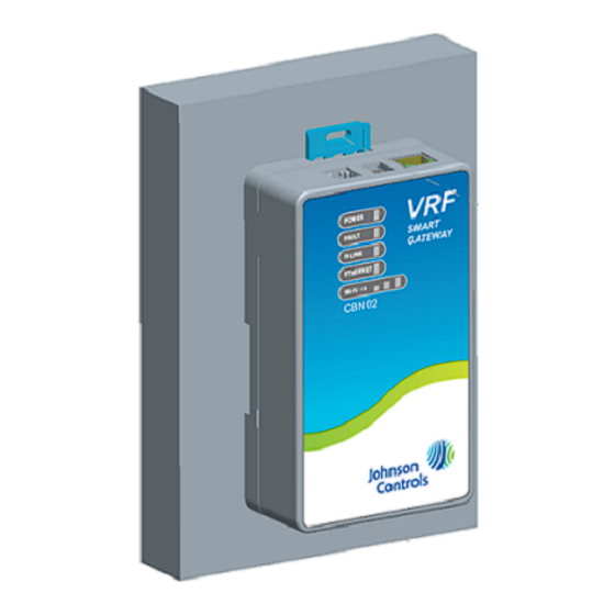
VRF Smart Gateway Installation Instructions
SI-VRFCBN02-0Sx
Update Software
Important: A software update may be available for your
device. Visit
VRFPro.com
nearest Johnson Controls representative
for the latest version. Refer to the VRF
Smart Gateway User's Guide
(LIT-12012385) for instructions on applying
updates.
Applications
The Johnson Controls® VRF Smart Gateway enables
the integration of the Hitachi VRF system with a building
automation system (BAS), such as the Metasys® system.
The VRF Smart Gateway performs this function by
communicating between the native H-Link
communications network of the Hitachi VRF system and
the open building standard BACnet®/IP network. The
VRF Smart Gateway intelligently provides the VRF device
and point data over the BACnet/IP network in a way that
the BAS can easily discover. The VRF Smart Gateway
therefore requires little or no post-integration configuration
within the BAS. The VRF Smart Gateway includes a
simple web server that provides a wireless mobile user
interface for configuring communication parameters and
performing VRF system discovery and device naming.
The wireless connection on the VRF Smart Gateway
allows users of a supported mobile device to be up to 30
m (100 ft, line of sight) away. Power must be supplied
using the provided external power supply.
VRF Smart Gateway Installation Instructions
North American Emissions
or contact your
Compliance
United States
This equipment has been tested and found to comply
with the limits for a Class A digital device pursuant to
Part 15 of the FCC Rules. These limits are designed to
provide reasonable protection against harmful
interference when this equipment is operated in a
commercial environment. This equipment generates,
uses, and can radiate radio frequency energy and, if not
installed and used in accordance with the instruction
manual, may cause harmful interference to radio
communications. Operation of this equipment in a
residential area may cause harmful interference, in which
case the users will be required to correct the interference
at their own expense.
RF Transmitters: Compliance Statement (Part 15.19)
This device complies with Part 15 of the FCC Rules.
Operation is subject to the following two conditions:
1. This device may not cause harmful interference, and
2. This device must accept any interference received,
including interference that may cause undesired
operation.
Warning (Part 15.21)
Changes or modifications not expressly approved by the
party responsible for compliance could void the user's
authority to operate the equipment.
RF Exposure (OET Bulletin 65)
To comply with FCC RF exposure requirements for
mobile transmitting devices, this transmitter should only
be used or installed at locations where there is at least
20 cm separation distance between the antenna and all
persons.
(barcode for factory use only)
Part No. 24-10143-1183, Rev. B
Software Release 1.0
Refer to the
QuickLIT website
for the most up-to-date version of this document.
Issued April 2017
1
Advertisement
Table of Contents

Related Manuals for Johnson Controls VRF Smart Gateway


Summary of Contents for Johnson Controls VRF Smart Gateway
- Page 1 VRF Smart Gateway intelligently provides the VRF device at their own expense. and point data over the BACnet/IP network in a way that the BAS can easily discover. The VRF Smart Gateway RF Transmitters: Compliance Statement (Part 15.19) therefore requires little or no post-integration configuration This device complies with Part 15 of the FCC Rules.
-
Page 2: Installation
Contact the nearest Johnson Controls representative to order. Mounting Locations The VRF Smart Gateway can be attached to a 1-1/8 in. Special Tools Needed (35 mm) DIN rail or a flat, vertical surface. Mounting the The unit supports both DIN rail and surface mounting unit on a ceiling or in a way that positions the front of the options. - Page 3 The screw types needed to mount the unit depend upon the surface to which the unit is mounted. The screw holes on the VRF Smart Gateway can accommodate M3.5 and #6 screws. For information on location considerations for maximizing...
-
Page 4: Wiring Consideration And Guidelines
Ethernet Port Wiring The Ethernet port on the VRF Smart Gateway is an 8-pin RJ-45 jack. The maximum allowable cable length is 328 ft (100 m). The Ethernet port on the VRF Smart Gateway Wiring Consideration and Guidelines... -
Page 5: External Power Supply Connections
Tout contact avec des default credentials. These credentials are included composants conducteurs de tensions dangereuses on a label in the VRF Smart Gateway Quick Start risque d'entraîner une décharge électrique et de Guide (Part No. 24-10737-156) that came with your provoquer des blessures graves, voire mortelles. -
Page 6: Reset Button Operation And Descriptions
For information on resetting the unit, see Table 4. The first time you log in to the VRF Smart Gateway, the Change Password and Passphrase web page Important: To use a unit that is reset to factory defaults, appears. You must change the Admin password and you must have the default login information Wi-Fi passphrase. - Page 7 The LEDs stop flashing for 2 seconds, and then the LEDs return to normal operation, based on the current state of the device. Resets all unit settings, including user profiles. For information on LED designations and flicker behavior, Table VRF Smart Gateway Installation Instructions...
-
Page 8: Status Indication Leds
Repair Information Flicker = Discovering VRF devices If the VRF Smart Gateway fails to operate within its specifications, replace it. The VRF Smart Gateway is not On Steady = Discovery complete a serviceable product; however, it does support software updates to enable feature enhancements. -
Page 9: Troubleshooting
In this case, reinstall the SSL key or certificate as described in the VRF Smart Gateway Network and IT Guidance Technical Bulletin (LIT-12012341). Refer to the VRF Smart Gateway User's Guide (LIT-12012385) for information on Ethernet settings and SSL settings. Technical Specifications... - Page 10 Table 4: VRF Smart Gateway Transmission Speeds Wireless Communication: 2.4 GHz ISM bands, 802.11 b/g/n, 11/22/54 Mbps Channel 6 preconfigured, supported CH 1 to 11 for United States and Canada, and CH 1 to 12 for all other countries Serial Communication (H-Link Bus):...
- Page 11 Industry Canada IC: 279A-MAPWIFI IC: RSS-210, ICES-003 Europe: CE Mark – Johnson Controls declares that this product is in compliance with the essential requirements and other relevant provisions of the RED Directive, the EMC Directive, and the Low Voltage Directive (LVD).
- Page 12 Table 6: IDU System Mode Metasys Enum Value Metasys Enum String Cool Heat Auto The following table lists the IDU custom enum values for SF-SPEED-C and SF-SPD. Table 7: IDU Fan Speed Metasys Enum Value Metasys Enum String VRF Smart Gateway Installation Instructions...
- Page 13 Table 7: IDU Fan Speed Metasys Enum Value Metasys Enum String High Auto The following table lists the outdoor units (ODUs) as exposed by the VRF Smart Gateway. Table 8: VRF BACnet Points for Outdoor Units BACnet Object Name Object Description...
- Page 14 Condenser Mode High Pressure Evaporator Mode Condenser Mode The following table lists the ODU custom enum values for INV-STATE and FAN-STATE. Table 12: ODU Inverter and Fan Status Metasys Enum Value Metasys Enum String Normal stop Fault VRF Smart Gateway Installation Instructions...
- Page 15 The following table lists the ODU custom enum values for PROT-CODE. Table 13: ODU Protection Code Metasys Enum Value Metasys Enum String Pressure ratio Pd rise prevention Current protection INV module temp rise prevent Compressor top overheat prevent Ps drop or rise prevention VRF Smart Gateway Installation Instructions...
- Page 16 Building Technologies & Solutions 507 E. Michigan Street, Milwaukee, WI 53202 Metasys® and Johnson Controls® are registered trademarks of Johnson Controls. All other marks herein are the marks of their respective owners.© 2017 Johnson Controls Published in U.S.A. www.johnsoncontrols.com VRF Smart Gateway Installation Instructions...
Need help?
Do you have a question about the VRF Smart Gateway and is the answer not in the manual?
Questions and answers