
Related Manuals for Johnson Controls YK-MAP1810-0E


Summary of Contents for Johnson Controls YK-MAP1810-0E
- Page 1 Mobile Access Portal Gateway Installation Guide YK-MAP1810-0E Building Technologies & Solutions Part No. 24-10737-00253 www.johnsoncontrols.com Rev. B 2021-01-27 *241073700253B* (barcode for factory use only)
- Page 2 Mobile Access Portal Gateway Installation Guide...
-
Page 3: Table Of Contents
Contents Introduction..............................5 North American Emissions Compliance......................6 United States............................6 Canada..............................6 Installation................................ 6 Parts Included............................6 Special Tools Needed..........................7 Portable Use..............................7 Mounting................................8 Permanent Mounting..........................8 Location Considerations........................9 Locking Screw (Stationary Unit Only)....................9 Permanent Mounting Locations......................9 Wiring................................ - Page 4 Mobile Access Portal Gateway Installation Guide...
-
Page 5: Introduction
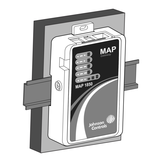
Introduction The Mobile Access Portal (MAP) Gateway is an alternate local display solution or a temporary portable commissioning device that enables you to leverage the power of mobility using smart phones, tablets, or laptop computers to interact with building automation equipment controls. The MAP Gateway serves up web pages through a built-in Wi-Fi access point or a tethered Ethernet connection, which allows users to view and edit equipment controller configuration parameters, setpoints, schedules, and alarms through a browser. -
Page 6: North American Emissions Compliance
North American Emissions Compliance United States This equipment has been tested and found to comply with the limits for a Class A digital device pursuant to Part 15 of the FCC Rules. These limits are designed to provide reasonable protection against harmful interference when this equipment is operated in a commercial environment. -
Page 7: Special Tools Needed
Special Tools Needed To use the MAP Gateway, you need a mobile device (tablet or smartphone) or computer (laptop or desktop) that supports Wi-Fi. If the unit is permanently mounted to a vertical surface without a DIN rail, you need screws to mount the unit. -
Page 8: Mounting
CAUTION Risk of Property Damage. Do not use the RJ-12 cable or any other field bus cable or electrical cable to support the weight of the MAP Gateway. Hanging the MAP Gateway from anything other than the supplied lanyard may result in damage to the product or peripheral equipment. -
Page 9: Location Considerations
The unit should be mounted in such a way that labels can be read if they are visible. (For example, do not mount the unit upside down, which puts the labels upside down.) Location Considerations Observe the following guidelines when mounting the MAP Gateway: •... - Page 10 To mount the bracket on a DIN rail: Securely mount a 7.5 cm (3 in.) or longer section of 35 mm (1-1/8 in.) DIN rail in the required space. On the bracket, pull the bottom mounting clip outward to the extended position. Figure 3: Positioning the Bracket on a DIN Rail Hang the bracket on the DIN rail by the hooks at the top of the DIN rail channel (on the back of the bracket), and position the bracket snugly against the DIN rail.
- Page 11 Figure 5: Sample Permanent Mounting, Side Screws Figure 6: Sample Permanent Mounting, DIN Rail Screw Holes To mount the bracket on a flat surface (such as a wall): Pull the bottom mounting clip outward to the extended position. Mark mounting hole locations on the wall using the dimensions shown in Figure 7, Figure 8, or Figure 9;...
- Page 12 Figure 7: Mounting Holes, Flat Mounting Note: The screw holes on the MAP Gateway can accommodate M3.5 and #6 screws. Mobile Access Portal Gateway Installation Guide...
- Page 13 Figure 8: Mounting Holes, Side Mounting Note: The screw holes on the MAP Gateway can accommodate M3.5 and #6 screws. Mobile Access Portal Gateway Installation Guide...
-
Page 14: Wiring
Figure 9: Mounting Holes, Flat Mounting, DIN Rail Screws Note: The screw holes on the MAP Gateway can accommodate M3.5 and #6 screws. Drill holes in the wall based on the locations marked in the preceding step, and insert wall anchors for each hole (if necessary). -
Page 15: Sa/Fc Port
• Provide some slack in the cable between the MAP Gateway and the controller or other device to which you are connecting. SA/FC Port The MAP Gateway has one RS-485 FC/SA bus port that connects through a supplied 6-pin modular jack and cable assembly. -
Page 16: Ethernet Port
Table 1: USB Port Pin Designations Pin Number (Both Signal Name Ends of Cable) +5 VDC Data - Data + No Connection Ground Ethernet Port The Ethernet port on the MAP Gateway is an 8-pin RJ-45 jack. The maximum allowable cable length is 100 m (328 ft). -
Page 17: Operation
WARNING Risk of Electric Shock. Disconnect or isolate all power supplies before making electrical connections. More than one disconnection or isolation may be required to completely de-energize equipment. Contact with components carrying hazardous voltage can cause electric shock and may result in severe personal injury or death. - Page 18 If the MAP Gateway is connected through the FC bus (point B on Figure 12), it has access to SE devices on that FC bus only when the FC bus protocol is BACnet MSTP. For individual units connected to the FC bus network, the FcBusMode is set to Wired Field Bus (BACnet MSTP) in the UCB display menu.
-
Page 19: Connecting To The Map Gateway Wi-Fi Network
Connecting to the MAP Gateway Wi-Fi Network Important: If you are going to use the MAP Gateway on Ethernet, you must plug it into external power before you attach the field bus adapter. Connect the FC/SA port of the MAP Gateway to the sensor bus or field busport of the equipment controllerusing the supplied RJ-12 cable (portable model) or field bus adapter (stationary model) (Figure 13). -
Page 20: Reset Button Operation And Descriptions
Network Reset function that resets Wi-Fi and Ethernet settings, and a Reset to Factory Defaults function that resets all unit settings (including user profiles). Reset to Factory Defaults also resets your SSL certificate to the Johnson Controls self-signed certificate that ®... - Page 21 Figure 14: Using the Reset Button Mobile Access Portal Gateway Installation Guide...
-
Page 22: Status Indication Leds
Table 2: Reset Button Operation and Descriptions Reset Function Reset Operation Reset Wi-Fi and Press and hold the reset button for 2 seconds. The Fault LED Ethernet Settings displays Slow Flicker behavior. (Network Reset) Release the reset button within 3 seconds. The Fault LED continues Slow Flicker behavior. -
Page 23: Map Gateway Led Designations And Descriptions
MAP Gateway LED Designations and Descriptions Table 3: LED Designations and Descriptions LED Name Color Normal Descriptions/Other Conditions Power Green On Steady (no Off = No power flashing) On Steady = Power supplied by primary voltage Fault Off = No faults/normal operation On Steady = Missing hardware, missing software, operating system has not yet initialized, or reset is in... -
Page 24: Repair Information
If the MAP Gateway fails to operate within its specifications, replace it. The MAP Gateway is not a serviceable product; however, it does support software updates to enable feature enhancements. For a replacement unit, software updates, or accessories, contact the nearest Johnson Controls representative. -
Page 25: Accessories (Order Separately)
Used for connecting directly to MS/TP Field Bus. Technical Specifications Table 6: MAP Gateway Product Code YK-MAP1810-0E: Extended temperature rated MAP Gateway (Includes MAP Gateway, field bus adapter and mounting bracket.) Power Consumption From SA/FC bus: 15 VDC at 2.7 VA maximum... - Page 26 Table 6: MAP Gateway Ambient Temperature Operating: -30°C to 70°C (-22°F to 158°F) Conditions Operating Survival: -30°C to 70°C (-22°F to 158°F) Non-Operating: -40°C to 70°C (-40°F to 158°F) Ambient Humidity Storage: 5% to 95% RH 30°C (86°F) maximum dew point conditions Conditions Operating: 5% to 95% RH, 30°C (86°F) maximum dew point conditions Transmission Power...
- Page 27 IC: RSS-210 cUL Listed File E107041, CAN/CSA E60730-1, Automatic Electrical Controls Europe: CE Mark—Johnson Controls declares that this product is in compliance with the essential requirements and other relevant provisions of the Radio Equipment Directive (RED), LVD Directive, and the EMC Directive.
-
Page 28: Product Warranty
The performance specifications are nominal and conform to acceptable industry standard. For application at conditions beyond these specifications, consult the local Johnson Controls office. Johnson Controls shall not be liable for damages resulting from misapplication or misuse of its products. -
Page 29: Contact Information
Contact information Contact your local branch office: www.johnsoncontrols.com/locations Contact Johnson Controls: www.johnsoncontrols.com/contact-us Mobile Access Portal Gateway Installation Guide... - Page 30 © 2021 Johnson Controls. All rights reserved. All specifications and other information shown were current as of document revision and are subject to change without notice.
Need help?
Do you have a question about the YK-MAP1810-0E and is the answer not in the manual?
Questions and answers