
Related Manuals for Grundfos Conex DIS-G


Summary of Contents for Grundfos Conex DIS-G
- Page 1 GRUNDFOS INSTRUCTIONS Conex DIS-G ® Gas warning controller Installation and operating instructions...
-
Page 2: Table Of Contents
Original installation and operating instructions Warning These complete installation and operating CONTENTS instructions are also available on Page www.Grundfos.com. Symbols used in this document Prior to installation, read these installation and operating instructions. Installation and Device settings operation must comply with local... -
Page 3: Device Settings
2. Device settings ® Note the key settings for the Conex DIS-G. General settings Parameters No. of sensors Sensor 1 Limit 1 Automatic sensor test Limit 2 Hysteresis Interval for automatic sensor test days Limit 2 confirmable Sensor 2 Limit 1 Delay for limit 2 Limit 2 Assignments for alarm relay... -
Page 4: General Information
Should you require further information or should you measuring a gas concentration encounter problems that are not handled in sufficient continuously or for control according to the depth in this manual, please contact Grundfos Water German MAK standard regarding Treatment. maximum allowable concentration. -
Page 5: Safety
5. Safety 5.3 Avoidance of danger This manual contains general instructions that must Warning be observed during installation, operation and Do not use the device for monitoring maintenance. This manual must therefore be read by constant concentrations. The device is the installation engineer and the relevant qualified designed for detecting leaks. -
Page 6: Identification
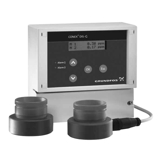
6. Identification 6.1 Nameplate DIS-G-P CCA-X-X, W-G 307-2000-10000 S/N: 09/46626 230/240V 50/60Hz, 5 VA, IP 65, W, P, X, CCA, X 96703835P1109050946626 ® Fig. 1 Nameplate, Conex DIS-G Pos. Description Type designation Model Serial number Voltage [V] Frequency [Hz] Product number Country of origin Year and week of production Marks of approval, CE mark, etc. -
Page 7: Type Key, Gas Warning Controllers
6.2 Type key, gas warning controllers Example: DIS-G, 1-D/A/HC 2-D/A/HC, W-G Example: DIS-G 1-D/A/HC 2-D/A/HC ® Conex gas warning system Dosing Instrumentation Standard DIS-G with gas detection Sensor 1 Chlorine gas/chlorine dioxide gas/ozone gas Ammonia gas Hydrochloric acid gas Sensor 2 Chlorine gas/chlorine dioxide gas/ozone gas Ammonia gas Hydrochloric acid gas... -
Page 8: Type Key, Gas Warning Systems, Prepacked (With Sensors And Sensor Note Equipment)
6.3 Type key, gas warning systems, prepacked (with sensors and sensor equipment) Example: DIS-G-P, CCA-X-X, W-G Example: DIS-G CCA- ® Conex gas warning system Dosing Instrumentation Standard DIS-G with gas detection Prepacked Sensor 1 Chlorine gas/chlorine dioxide gas, amperometric measurement Ozone gas, amperometric measurement Chlorine gas, potentiostatic measurement Chlorine dioxide gas, potentiostatic measurement... -
Page 9: Product Description And Accessories
The measuring parameter does not have to be set in the software (or device). It is selected using the corresponding sensor. Conex DIS-G Alarm 1 Alarm 2 Fig. 2 Gas warning system, example of an application... -
Page 10: Dimensional Sketches
® • the Conex DIS-G gas warning controller • warning and safety equipment: horn, flashing warning system, sprinkling installation. 7.2 Dimensional sketches 72.5 Conex DIS-G Alarm 1 Alarm 2 165.5 ® Fig. 3 Conex DIS-G... -
Page 11: Technical Data
8. Technical data 8.1 Signal inputs and outputs Observe the permissible temperature Five relay outputs, NO Caution range of the sensors! (normally open); maximum 250 V/6 A, maximum 550 VA ohmic load Note Observe the accuracy of the sensor! • two relays for the limit Relay outputs values of each of the two Electronics... -
Page 12: Sensors
8.3 Sensors Amperometric sensor disc Cl , ClO and O Connection via 2-wire cable 0.5 mm with single screen. Maximum length (maximum distance between the sensor disc and gas warning controller): 100 metres. 91835237 (314-011) / 96687714 (314-013) include the wall housing with sensor disc. 8.3.1 Measuring parameter and working range for amperometric sensors Measuring Temperature... -
Page 13: Installation
Risk of malfunction or damage to the large machines, etc. ® Conex DIS-G! Grundfos accepts no Caution liability for damage caused by incorrect If these assembly requirements are not transportation or missing or unsuitable... -
Page 14: Installation Of The Conex ® Dis-G
Drilling diagram of the Conex DIS-G Enclosure class IP65 is only guaranteed if the terminal cover is correctly sealed! Caution Do not damage the terminal cover gasket! The terminal cover gasket must fit exactly! Conex DIS-G Alarm 1 Alarm 2 Fig. 5 Mounting drawing... -
Page 15: Commissioning / Electrical Connections
10. Commissioning / electrical connections Warning Switch off the power supply before installing! Enclosure class IP65 is only guaranteed if the terminal covers are closed and the appropriate cable glands or dummy caps fitted. Warning Switch off the power supply before connecting the power supply cable and the relay contacts! For safety reasons, the protective conductor must be connected... -
Page 16: Conex ® Dis-G Terminal Assignment
® 10.1 Conex DIS-G terminal assignment 13 15 17 10 12 14 16 20 21 23 24 18 19 26 27 29 30 > 100 m > 1000 m Power supply ® Fig. 6 Conex DIS-G terminal 10.2 Power supply connection Before connecting, check that the values for the supply voltage and frequency Caution... -
Page 17: Relay Outputs
20 metres (321-130/20) Connection cable for amperometric 96725673 gas sensors, 50 metres (321-130/50) The wire colours refer to Grundfos cable. Sensor 1: • Connect the brown wire (+) to terminal 26. • Connect the white wire (-) to terminal 27. -
Page 18: Operation
11. Operation Pos. Description 11.1 Initial start-up [Up] button • Increases values. If a sprinkling installation is connected, • Navigates in display mode. first shut off the water supply. On initial [Down] button start-up, the relevant limit value may be Note exceeded during the sensor start-up •... - Page 19 11.4.1 Changing to the "Configuration" menu 11.4.2 Selecting operating language One of the following menus is displayed in the This item appears first in the "Configuration" menu display mode. and does not need to be selected. Measured value Language x.xx ppm English 1.
- Page 20 11.4.5 Selecting the assignments of the 11.4.6 Setting the confirmability of limit value 2 alarm relay If limit value 2 is exceeded by one of the two sensors, a sprinkling installation is usually triggered, M1 - limit 1 for example to bond the leaking chlorine. Alarm relay Normally the relay for limit value 2 remains activated until the measured value drops down below limit...
- Page 21 11.4.7 Adjusting the zero point of the sensors 8. Press [OK]. Warning 0-point If you apply this function incorrectly, adjustment measurement faults may occur, or the measurements may not be correct! 9. Press [OK]. The sensor may have a deviation from its zero point, –...
-
Page 22: Basic Settings In The "Parameter" Menu
11.5 Basic settings in the "Parameter" 11.5.3 Setting automatic sensor test menu The device offers the possibility to carry out automatic sensor tests at regular intervals. 11.5.1 Changing to the "Parameter" menu Test period One of the following menus is displayed in the display mode. -
Page 23: Commissioning
11.5.5 Setting the hysteresis for the limit values A hysteresis can be set for the limit values of each sensor (the sensors are set separately, but the hysteresis of the two limit values of one sensor is equal). Hysteresis Limit 2 1/2 hysteresis Limit 1 1/2 hysteresis... - Page 24 11.7.2 Reading error messages 11.7.4 Exceeding limit values • In the display mode, change to the next error If a limit value of a sensor is exceeded, the following messages by pressing the [Down] button. occurs: – If more than one error message occurs, •...
-
Page 25: Fault Finding
12. Fault finding In case of measurement faults, see the Note manual of the gas sensors. Fault Cause Remedy No display No power supply. Connect the power supply. following start-up. Display Open circuit in cable between Check the connection cable, permanently at sensor and gas warning device. -
Page 26: Maintenance
13. Maintenance 13.1.2 Resetting to factory settings 1. Press [OK] several times until the "Factory The device is maintenance-free. setting" menu is displayed. Repairs can only be carried out in the factory by authorised personnel. Factory setting 13.1 Resetting the device to factory settings 2. -
Page 27: Disposal
Use appropriate waste "1 sensor". collection services. If this is not possible, contact the Checking the current outputs for measured nearest Grundfos company or service workshop. value 1 1. Press [OK] to change to the items. Subject to alterations. - Page 28 Declaration of conformity GB: EU declaration of conformity DE: EU-Konformitätserklärung We, Grundfos, declare under our sole responsibility that the products Wir, Grundfos, erklären in alleiniger Verantwortung, dass die Conex® DIA-G, DIS-G, DIS-D, DIS-PR, to which the declaration below Produkte Conex® DIA-G, DIS-G, DIS-D, DIS-PR, auf die sich diese relates, are in conformity with the Council Directives listed below on Erklärung beziehen, mit den folgenden Richtlinien des Rates zur...
- Page 30 Argentina China Germany Bombas GRUNDFOS de Argentina S.A. Grundfos Alldos GRUNDFOS GMBH Ruta Panamericana km. 37.500 Centro Dosing & Disinfection Schlüterstr. 33 Industrial Garin ALLDOS (Shanghai) Water Technology 40699 Erkrath 1619 - Garin Pcia. de B.A. Co. Ltd. Tel.: +49-(0) 211 929 69-0 Phone: +54-3327 414 444 West Unit, 1 Floor, No.
- Page 31 Telefax: +66-2-725 8998 Fax: + 370 52 395 431 Phone: +381 11 26 47 877 / 11 26 47 Turkey Malaysia GRUNDFOS POMPA San. ve Tic. Ltd. Telefax: +381 11 26 48 340 GRUNDFOS Pumps Sdn. Bhd. Sti. Singapore 7 Jalan Peguam U1/25 Gebze Organize Sanayi Bölgesi...
- Page 32 96681484 0516 ECM: 1183579 www.grundfos.com...
Need help?
Do you have a question about the Conex DIS-G and is the answer not in the manual?
Questions and answers