Table of Contents
Advertisement
Quick Links
PleaSe reaD THIS enTIre Manual BeFOre YOu InSTall anD uSe YOur new FIrePlace. FaIlure TO
FOllOw InSTrucTIOnS MaY reSulT In PrOPerTY DaMage, BODIlY InjurY, Or eVen DeaTH.
FOr uSe In THe u.S. anD canaDa. SuITaBle FOr InSTallaTIOn In MOBIle HOMeS
IF THIS FIrePlace IS nOT PrOPerlY InSTalleD, a HOuSe FIre MaY reSulT. FOr YOur SaFeTY, FOllOw
InSTallaTIOn DIrecTIOnS.
cOnTacT lOcal BuIlDIng Or FIre OFFIcIalS aBOuT reSTrIcTIOnS anD InSTallaTIOn InSPecTIOn
reQuIreMenTS In YOur area.
cOnTacT YOur lOcal auTHOrITY (SucH aS MunIcIPal BuIlDIng DeParTMenT, FIre DeParTMenT, FIre
PreVenTIOn Bureau, eTc.) TO DeTerMIne THe neeD FOr a PerMIT.
ceTTe guIDe D'uTIlISaTIOn eST DISPOnIBle en FrancaIS. cHez VOTre cOnceSSIOnnaIre De HarMan
HOMe HeaTIng.
Installation & Operating Manual
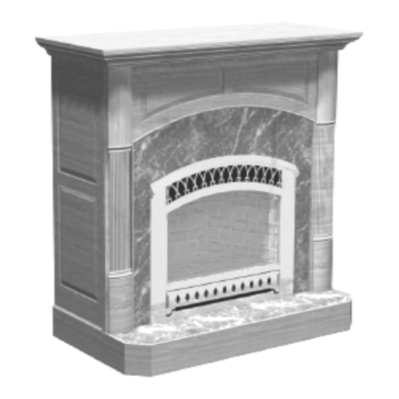
The Serenity III - HB 38 DV
"Ce manuel est disponible en Français sur demande"
SaFeTY nOTIce
SaVe THeSe InSTrucTIOnS.
SaVe THeSe InSTrucTIOnS.
R14
R1
#3-90-04238
Advertisement
Table of Contents

Related Manuals for Harman The Serenity III HB 38 DV


Summary of Contents for Harman The Serenity III HB 38 DV
- Page 1 In YOur area. cOnTacT YOur lOcal auTHOrITY (SucH aS MunIcIPal BuIlDIng DeParTMenT, FIre DeParTMenT, FIre PreVenTIOn Bureau, eTc.) TO DeTerMIne THe neeD FOr a PerMIT. ceTTe guIDe D’uTIlISaTIOn eST DISPOnIBle en FrancaIS. cHez VOTre cOnceSSIOnnaIre De HarMan HOMe HeaTIng. SaVe THeSe InSTrucTIOnS.
- Page 2 warnIng: If the information in these instructions wHaT TO DO IF YOu SMell gaS are not followed exactly, a fire or explosion may • Do not try to light any appliance. result causing property damage, personal injury • Do not touch any electrical switch; do not use or loss of life.
-
Page 3: Table Of Contents
Safety Precautions Operation Specifications Installation Face Installation Venting Damper Settings Changing to LP Log Placement Option Installation Thermostat Remote Control Remote Register Kit Maintainence Wiring Diagrams Troubleshooting Warranty Manufactured by: Harman Home Heating 352 Mountain House Rd. Halifax PA 17032... -
Page 4: Introduction
Introduction The Harman Serenity III Direct Vent Gas Fireplace When operating your Harman Serenity III Gas is a listed gas-fired direct vent room fireplace tested Fireplace, respect basic safety standards. Read these by Intertek Testing Services/Warnock Hersey to ANSI instructions carefully before you attempt to operate Z21.88-2002-CSA 2.33-2002. - Page 5 IMPORTANT FEATURE Air Gate Blower System Typically in gas fireplaces the blower (which is usually an option) is placed to blow air up the back of the firebox 200% To 300% without any method to keep the air pressure from being lost.
-
Page 6: Operation
OPERATION... - Page 7 OPERATION Operation High-Low HOW TO LIGHT THE FIRE Gas Control 1. STOP! Read the safety information on the front cover. 2. If using the optional thermostat, set the thermostat to it’s lowest setting. 3. Turn off all electrical power to the appliance. 4.
- Page 8 OPERATION 15. Set the High-Low Regulator to the desired setting: Turn fully counterclockwise for High and fully Bottom rear view of burner module. clockwise for Low. 16. Press the rear burner switch to the “ON” or “OFF” position as desired. This switch will return to the center position after it is pressed.
-
Page 9: Specifications
SPECIFICATIONS Top Standoffs Vent Collar Accordion Heat Exchanger Glass Door Brick Burner Module Electrical Box On-Off- Thermostat Switch Blower Speed Switch Ignitor Battery On-Off-Pilot Knob Pack Blower Rear Burner Hi-Low Knob Switch raTIngS NATURAl PRoPANe Input Rating (Btu/hr)(0-4500 ft.)(0-1375 m) 43500 43500 Min. - Page 10 SPECIFICATIONS MINIMUM CLEARANCES FROM COMBUSTIBLE CONSTRUCTION Unit to floor 0 in. Face to side wall 7 in. Unit to top stand-offs 0 in. Unit to side stand-offs 0 in. Unit to rear stand-offs 0 in. Top of Glass to 7” Mantel 26in.
- Page 11 SPECIFICATIONS Corner Electrical Hook-up 10.894 10.865 10.270 10.270 6.865 1.000 Gas In 42.376 21.135 43.085 1.000 22.135...
-
Page 12: Installation
INSTALLATION Only For Qualified Installers Installation Options This section deals with basic installation with an Arch face. It does not describe every possible way to install this fireplace. This is why it is important to have a qualified installer do the installation. The Serenity III can be laid in stone, brick, or other masonry products. - Page 13 INSTALLATION Only For Qualified Installers Placement This appliance must be electrically connected and Here are some of the things that will affect the exact grounded in accordance with local codes or , in the placement of the fireplace. absense of local codes, with the current edition of 1.
- Page 14 INSTALLATION Only For Qualified Installers Installing fireplace in a wall with an arch face, ceramic tile facing, and a wood mantel. Noncombustible Noncombustible material such as Dura-rock must be used as 1 inch thick facing on the front of the fireplace cabinet. A one inch space under the front edge of the fireplace allows room for hearth material.
- Page 15 INSTALLATION Only For Qualified Installers Installing The Face To install the face, place the hooks on the bottom rear of the face into the hook slots on the fireplace. Next with the top latch handles in the horizontal position push the face against the fireplace and swing the latches straight down causing them to enter the top face slots.
- Page 16 INSTALLATION Only For Qualified Installers Burn Only the Fuel for which the Heater is Natural Gas: Equipped Maximum inlet pressure 7.0” w.c. (1.74 kPa) The Serenity III Direct Vent will burn either natural gas Minimum inlet pressure 5.0” w.c. (1.25 kPa) or propane, but requires a change over kit for propane.
-
Page 17: Venting
Wall Strap 1281 Snorkel Termination (36”) 1282 Snorkel Termination (14”) 1284 Horizontal Square Termination 1280 Vertical Termination 1291 Vertical Termination, High Wind 1250 Vinyl Siding Standoff 1222D (Only available from Harman) 8” x 5” to 6 ” x 4” Adaptor... - Page 18 VENTING Only For Qualified Installers Selkirk Direct-Temp - cross reference Selkirk Direct-Temp Simpson Dura-Vent Direct Vent gS Stock no. Description Stock no. Description 4DT-6 6” Pipe length, Galvanized 6” Pipe length, Galvanized 4DT-6B 6” Pipe length, Black 908B 6” Pipe length, Black 4DT-9 9”...
- Page 19 VENTING Only For Qualified Installers Secure VenT DIrecT VenT SYSTeM - 4” x 6-5/8” and 5” x 8” cross reference list Secure Simpson Dura-Vent Secure Simpson Dura-Vent Direct Vent gS Vent Direct Vent gS Vent Description Stock no. cat no. Stock no.
- Page 20 VENTING Only For Qualified Installers Montigo Direct Vent Standard Series Direct Vent (4”/ 7”) Description Order code HOrIzOnTal TerMInaTIOnS 3” length, no mounting frame (use with MSR or MoSR) MTo3 MTo-3 MTo-3F 3” Termination, with integral mounting frame MTo3F VerTIcal TerMInaTIOn Termination for vertical installations MVTK1 Includes MXT-10 adaptor (for straight, vertical installations)
- Page 21 VENTING Only For Qualified Installers Montigo Direct Vent Standard Series Direct Vent (4”/ 7”) Description Order code SnOrkel TerMInaTIOnS 18” vertical rise SNK47-2 30” vertical rise SNK47-3 HeaT guarD Fits all Standard Series (4/7”) terminations MTKoG HeaT SHIelDS SNK47-2, SNK47-3 Through-the-wall radiation Shield for 4”/7”...
- Page 22 VENTING Only For Qualified Installers Montigo Direct Vent Premium Series Direct Vent (5”/8”) Description Order code HOrIzOnTal TerMInaTIOnS 3” Termination with no mounting frame (male connector) PTo3 (use with MSR or MoSR). 3” Termination & mounting frame (male connector) PTo3F PTo-3 PTo-3F VerTIcal TerMInaTIOn...
- Page 23 VENTING Only For Qualified Installers Montigo Direct Vent Premium Series Direct Vent (5”/8”) Description Order code SnOrkel TerMInaTIOnS 18” vertical rise SNK58-2 30” vertical rise SNK58-3 InSulaTeD OFFSeT BOx M38DV-ST offset box. Used only on the M38DV-ST when a shelf or T.V.
- Page 24 VENTING Only For Qualified Installers Venting with 8” x 5” Pipe This appliance must not be connected to a chimney flue serving a separate solid fuel burning appliance. Maximum of four 45 elbows allowed. Subtract three feet of total horizontal pipe length for each of the 3rd and 4th 45 elbows used.
- Page 25 VENTING Only For Qualified Installers Venting with 6 ” x 4” Pipe Maximum of four 45 elbows allowed. Subtract three feet of total horizontal pipe length for the 3rd and 4th 45 elbow used. Maximum of two 90 elbows allowed. Subtract five feet of total horizontal pipe length for second elbow.
- Page 26 VENTING Only For Qualified Installers Requirements for Terminating the Venting WARNING: Venting terminals must not be recessed into a wall or siding. In addition, the following must be observed: (See diagram on next page.) Canadian Installations US Installations 12 Inches (30 cm) 12 inches (30 cm) Clearance above grade, veranda, porch, deck, or balcony...
- Page 27 VENTING Only For Qualified Installers...
-
Page 28: Damper Settings
VENTING Only For Qualified Installers Damper Settings Vent damper in the number “4” position Maximum Draft Minimum Draft A vent damper is provided to allow fine tuning of the draft. Too little draft will cause flames to be too long with black tips and too much draft will cause flames to be short and blue. -
Page 29: Changing To Lp
INSTALLATION Only For Qualified Installers Changing to LP Remove screw Remove Orifice Cover Remove Air Deflector Remove Rear Burner by Remove Screw sliding to the left. Lift up on front of burner/grate/ screen assembly and then slide left Remove about 1/2”. The assembly can then Flame Bridge be removed. - Page 30 INSTALLATION Only For Qualified Installers Orifice Chart Remove Orifices with a 1/2” wrench or deep well socket. The larger Natural Propane orifice always goes to the front. Front Rear Front Rear Note: The higher the orifice number the smaller hole in the tip.
-
Page 31: Log Placement
INSTALLATION Only For Qualified Installers Log Placement Rear Log Pins Rear Log Front Log Pin Front Log Side Log Top Log Locate two holes in bottom of rear log. Place the rear log Place the front log down over the pin shown above. The front down over the two pins to locate the log. -
Page 32: Thermostat
INSTALLATION (Options) Only For Qualified Installers Connecting an Optional Thermostat If an optional thermostat is used, it must be plugged into the terminal strip located in the lower left front corner of the heater. When installing a millivolt control system, use only a special low resistance thermostat. -
Page 33: Remote Register Kit
INSTALLATION (Options) Only For Qualified Installers Optional Remote Register Kit Register Kit Includes remote register box with blower, speed control, two 8 foot sec- Flex Pipe tions of 6” flex pipe, 6” round to 3” x 10” transition, and automatic damper assembly. - Page 34 INSTALLATION (Options) Only For Qualified Installers Optional Wall Register Kit The Serenity is designed for use with one or two register kits. Each kit can have twenty feet of duct between the fireplace and the register box. The registers can be mounted one floor above or below the fireplace.
- Page 35 INSTALLATION (Options) Only For Qualified Installers Blower Cover Wall Mounting Brackets Mount blower cover as shown . Install wall mounting brackets to side of blower box with three screws. Blower Box Blower Assembly Box Cover Register Install and finish drywall as desired. Install blower box between wall studs as shown.
- Page 36 INSTALLATION (Options) Only For Qualified Installers Floor Register Installation The difference between the wall register and floor register is the register itself and the mounting brackets. The wall register mounts on the wall with two screws. The floor register mounts in the floor and is held in place by gravity.
-
Page 37: Wiring Diagrams
INSTALLATION (Options) Only For Qualified Installers Installing the Floor Register Breakoff Tabs The blower box mounting bracket is designed to allow mounting into an existing floor. However, it is easier to install all components at the time of house construction. The mounting bracket assumes that floor joists are on 16”... - Page 38 INSTALLATION (Options) Only For Qualified Installers 8. Install register by sliding it down into the Blower Assembly Ready to Install. opening. Make sure the speed control door is over the speed control. The register is designed to allow for a variation in floor thickness.
- Page 39 The following procedures should be performed only from your Harman dealer. To replace the gasket, follow by a qualified service person. The gas supply should this procedure.
- Page 40 MAINTENANCE Air Flow It is essential that air flows freely into the bottom grill Air Out and out of the top grill. Do not place objects in front of the grills. Check blower annually for buildup caused by dust and pet hair.
- Page 41 MAINTENANCE...
- Page 42 MAINTENANCE...
- Page 44 Serenity III (HB38) Service Parts Beginning Manufacturing Date: n/a gas Fireplace - DV ending Manufacturing Date: july 2009 1-70-08770 (Top Vent), 1-70-08771 (rear Vent) IMPoRTANT: THIS IS DATeD INFoRMATIoN. When requesting service or replacement Stocked parts for your appliance please provide model number and serial number. All parts listed in this manual may be ordered from an authorized dealer.
- Page 45 Serenity III (HB38) Service Parts Beginning Manufacturing Date: n/a ending Manufacturing Date: july 2009 IMPoRTANT: THIS IS DATeD INFoRMATIoN. When requesting service or replacement Stocked parts for your appliance please provide model number and serial number. All parts listed in this manual may be ordered from an authorized dealer. at Depot ITeM DeScrIPTIOn...
- Page 46 Serenity III (HB38) Service Parts Beginning Manufacturing Date: n/a ending Manufacturing Date: july 2009 IMPoRTANT: THIS IS DATeD INFoRMATIoN. When requesting service or replacement Stocked parts for your appliance please provide model number and serial number. All parts listed in this manual may be ordered from an authorized dealer. at Depot ITeM DeScrIPTIOn...
-
Page 47: Troubleshooting
TROUBLE SHOOTING Only For Qualified Installers Natural Gas Manifold Pressure Inlet Pressure 3.5 inches 5 to 7 inches Pilot Adjuster Propane Manifold Pressure Inlet Pressure 11 10 inches to 13 inches Pilot Adjuster... - Page 48 TROUBLE SHOOTING Only For Qualified Installers Pilot does not light after many tries Check ignitor wire and Look to see if a spark jumps Reconnect or replace connections from piezo ignitor from the ignitor electrode Ignitor wire. to ignitor ceramic at pilot. to the pilot when the ignitor button is pushed.
- Page 49 TROUBLE SHOOTING Only For Qualified Installers Pilot does not stay lit Check inlet pressure Correct inlet pressure Good Adjust pilot adjustment to Check size of pilot flames achieve proper flame. Good Check Milivolt output Replace Thermocouple of thermocouple. Should be 10 or more MV. Good Replace Valve...
- Page 50 TROUBLE SHOOTING Only For Qualified Installers Main Burner will not light (with valve in “on” position) Light pilot Is Pilot lit Check Thermopile voltage at terminals marked TP on valve. too low Replace Thermopile Should be approximately 200 mv with switch “on” and approximately 400 mv with switch “off”.
- Page 51 TROUBLE SHOOTING Only For Qualified Installers Rear burner does not light Do you hear a click sound Check rear orifice for when you move the rear blockage burner switch back and forth from “off” to “on”. Check batteries Install new batteries Good Repair any loose Check wire connections...
-
Page 52: Warranty
Hearth & Home Technologies Inc. LIMITED LIFETIME WARRANTY Hearth & Home Technologies Inc., on behalf of its hearth brands (”HHT”), extends the following warranty for HHT gas, wood, pellet, coal and electric hearth appliances that are purchased from an HHT authorized dealer. WARRANTY COVERAGE: HHT warrants to the original owner of the HHT appliance at the site of installation, and to any transferee taking ownership of the appliance at the site of installation within two years following the date of original purchase, that the HHT appliance... - Page 53 WARRANTY CONDITIONS: • This warranty only covers HHT appliances that are purchased through an HHT authorized dealer or distributor. A list of HHT authorized dealers is available on the HHT branded websites. • This warranty is only valid while the HHT appliance remains at the site of original installation. •...
Need help?
Do you have a question about the The Serenity III HB 38 DV and is the answer not in the manual?
Questions and answers