Mindray Passport 12 Service Manual
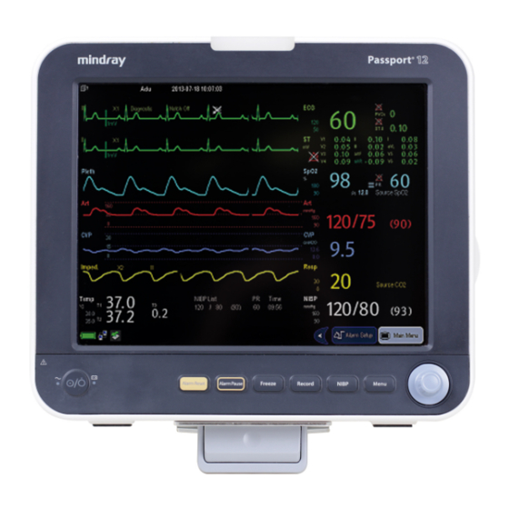
Patient monitor
Hide thumbs
Also See for Passport 12:
- Operator's manual (284 pages) ,
- Quick reference manual (37 pages) ,
- Service manual (110 pages)
Table of Contents
Advertisement
Quick Links
Advertisement
Table of Contents
Troubleshooting

Subscribe to Our Youtube Channel
Related Manuals for Mindray Passport 12


Summary of Contents for Mindray Passport 12
- Page 1 Passport 12/Passport 8 Patient Monitor Service Manual...
-
Page 3: Revision History
This manual may refer to information protected by copyrights or patents and does not convey any license under the patent rights of Mindray, nor the rights of others. Mindray does not assume any liability arising out of any infringements of patents or other rights of third parties. - Page 4 Contents of this manual are subject to changes without prior notice. All information contained in this manual is believed to be correct. Mindray shall not be liable for errors contained herein nor for incidental or consequential damages in connection with the furnishing, performance, or use of this manual.
- Page 5 Exemptions Mindray's obligation or liability under this warranty does not include any transportation or other charges or liability for direct, indirect or consequential damages or delay resulting from the improper use or application of the product or the use of parts or accessories not approved by Mindray or repairs by people other than Mindray authorized personnel.
- Page 6 Contact Information Manufacturer: Shenzhen Mindray Bio-Medical Electronics Co., Ltd. Address: Mindray Building, Keji 12th Road South, Hi-tech Industrial Park, Nanshan, Shenzhen 518057 P.R. China Tel: +86 755 81888998 Fax: +86 755 26582680 Website: www.mindray.com Distributor: Mindray DS USA, Inc. Address:...
- Page 7 Preface Manual Purpose This manual provides detailed information about the assembly, disassembly, and testing of the equipment to support effective troubleshooting and repair. It is not intended to be a comprehensive, in-depth explanation of the product architecture or technical implementation. Observance of the manual is a prerequisite for proper equipment maintenance and prevents equipment damage and personnel injury.
- Page 8 FOR YOUR NOTES Passport 8/12 Service Manual...
-
Page 9: Table Of Contents
Contents 1 Safety ....................................1-1 1.1 Safety Information ......................................1-1 1.1.1 Warnings ......................................1-2 1.1.2 Cautions ....................................... 1-2 1.1.3 Notes ........................................1-2 1.2 Equipment Symbols ....................................... 1-3 2 Theory of Operation ................................2-1 ... - Page 10 3.2.5 Wireless Network Specification ..............................3-3 3.2.6 Network Setup Overview ................................3-4 3.2.7 Setting the Network Type ................................3-5 3.2.8 Setting the Wireless Network ............................... 3-5 3.2.9 Setting the WLAN Band and Channels ............................. 3-6 ...
- Page 11 7.3.6 Removing the Recorder (Optional) ............................7-4 7.3.7 Removing Battery Interface Board and Power Board (Passport 8) ................. 7-5 7.3.8 Removing the Battery Interface Board and Power Board (Passport 12) ............... 7-6 7.3.9 Removing the Power Management Board ..........................7-7 ...
- Page 12 8.2.8 IBP_C.O._Sidestream CO Module Assembly........................8-10 8.2.9 IBP_C.O._Microstream CO Module Assembly ........................8-11 8.3 Passport 12 ........................................8-13 8.3.1 Main Unit ......................................8-13 8.3.2 Front Housing Subassembly............................... 8-14 8.3.3 Rear Housing Assembly ................................8-16 ...
-
Page 13: Safety
Safety 1.1 Safety Information WARNING Indicates a potential hazard or unsafe practice that, if not avoided, will result in death or serious injury. CAUTION Indicates a potential hazard or unsafe practice that, if not avoided, could result in minor personal injury or product/property damage. -
Page 14: Warnings
WARNING All installation operations, expansions, changes, modifications and repairs of this product are conducted by Mindray authorized personnel. There is high voltage inside the equipment. Never disassemble the equipment before it is disconnected from the AC power source or the battery. -
Page 15: Equipment Symbols
1.2 Equipment Symbols Some symbols may not appear on your equipment. Caution Refer to instruction manual/ booklet Power ON/OFF (for a part of the Battery indicator equipment) Alternating current VGA output Equipotentiality Graphical record USB connector Network connector Zero key Input/Output Check sensor Calibrate key... - Page 16 FOR YOUR NOTES Passport 8/12 Service Manual...
-
Page 17: Theory Of Operation
Theory of Operation 2.1 The Basics This monitor is designed to monitor a fixed set of physiological parameters including ECG, respiration (Resp), temperature (Temp), SpO , pulse rate (PR), non-invasive blood pressure (NIBP), invasive blood pressure (IBP), cardiac output (C.O.), carbon dioxide (CO ), and anesthetic gas (AG). -
Page 18: System Connections
The above figure shows a system consists of the Passport 12/8 patient monitor and its peripheral devices. The Passport 12/8 patient monitor: Can be used for monitoring the physiological parameters, giving alarms and reviewing patient data, etc. Supports recorder. -
Page 19: Connectors For Peripheral Devices
2.2.2 Connectors for Peripheral Devices On the back of the monitor you can find all connectors for peripheral devices. Passport 12 Rear View AC power input: used to connect an AC power source (100 to 240 VAC, 50/60 Hz). Equipotential terminal: used to connect the equipotential terminal of other equipment. - Page 20 Passport 8 Rear View Equipotential terminal: used to connect the equipotential terminal of other equipment. AC power input: used to connect an AC power source (100 to 240 VAC, 50/60 Hz). Parameter Module slot: used to connect the parameter module. Multifunctional connector: ...
-
Page 21: Main Unit
2.3 Main Unit The main unit of the monitor consists of two parts: Front housing assembly: main board, keypad board assembly (knob), display, touchscreen, alarm lamp board, power switch, and indicator board. Rear housing assembly: power board (AC/DC), power management board, battery pad, interface board, recorder, speaker, and multi-parameter module which includes two types of SpO stacking board. -
Page 22: Front Housing Assembly
2.4 Front Housing Assembly Screws fastening the front and rear housing Alarm lamp board Main board Wi-Fi module Keypad Touchscreen control board Lock hatch 2.4.1 Main Board The main board is the control center of the system. It provides communication, display, and data storage functions, including: ... -
Page 23: Alarm Lamp Board
2.4.3 Alarm Lamp Board The alarm lamp board is located at the top of front housing. It has two-color indicators, red and yellow. The alarm lamp board directly connects the main board through a cable. It is controlled directly by the main board. 2.4.4 Touchscreen and Touchscreen Control Board The touchscreen control board drives the touchscreen and implements communication with the monitor. -
Page 24: Ac/Dc Power Board
2.5.1 AC/DC Power Board The AC/DC power board transforms the input AC into DC power, which is the power source for all voltages in the monitor. 2.5.2 Power Management Board The power management board mainly performs DC/DC conversion, power management, and transmission of external connector signals: ... -
Page 25: Spo 2 Board
IBP module Module IBP + C.O. Module IBP + C.O. + CO (Mindray Sidestream CO /Microstream CO ) module IBP + C.O. + AG (w O ) module 2.6.1 Module Converter The module converter performs signal conversion function. -
Page 26: Converter
2.6.2 Converter The converter performs the following functions: Converting 12 V to 5 V DC power Converting RS232 level to TTL level Detecting and identifying the modules 2.6.3 IBP + C.O. Module The IBP/C.O. module supports C.O. and 2-channel measurement of IBP. The module consists of an amplification circuit, AD converter, CPU circuit and power isolation circuit. -
Page 27: Unpacking And Installation
Unpacking and Installation 3.1 Unpacking the Equipment Open the package and take out the packing list. Check that all the articles included in the packing list are available and the quantity and specification are correct. Make sure that: All the optional parts purchased by the customer shall also be checked. ... -
Page 28: Preparation For Installation
0 to 40 15% to 95% 57.3 to 105.3 Storage environment -20 to 60 10% to 95% 57.3 to 105.3 NOTE The environmental specifications of unspecified parameters are the same as those of Passport 12 main unit. Passport 8/12 Service Manual... -
Page 29: Electrical Requirements
3.2.2 Electrical Requirements Check cables and power cords. Make sure that: Check that the system cables, power cords, and power plugs are not damaged, and pins are not loose. In case of any damage, remove it from use. The insulation of patient cables and leadwires is not damaged, and connectors are not loose. WARNING ... -
Page 30: Network Setup Overview
3.2.6 Network Setup Overview In the [Network Setup] menu, you can set IP address, subnet mask and gateway. You should not change the patient monitor’s IP address randomly. If you want to know details about IP address setup, contact Mindray Technical Support Department.. -
Page 31: Setting The Network Type
3.2.7 Setting the Network Type The monitor supports both wired and wireless network. To set the network type: Select [Main Menu]→[Maintenance>>]→[User Maintenance>>]→enter the required password→select [Ok]. Select [Network Setup >>]. Select [Monitor Network Setup >>]. Set [Network Type] to [LAN] or [WLAN]. 3.2.8 Setting the Wireless Network The patient monitors can be connected to a wireless network via a built-in Wi-Fi module. -
Page 32: Setting The Wlan Band And Channels
To test the availability of the wireless network, follow this procedure: Select [WLAN Test >>] in the [Monitor Network Setup] menu. Enter the [IP Address] of the wireless AP in the [WLAN Test >>] menu. Click [Connection Test]. If the designated IP can be successfully connected, the reply time is displayed. If the connection fails, the reply is timeout. -
Page 33: Setting The Network Service Quality Level
3.2.10.2 Deleting Certificates To delete certificates from the monitor: Select [Main Menu]→[Maintenance>>]→[User Maintenance>>]→enter the required password.→[Network Setup >>]→[Certificates Maintenance >>]→[Delete certificates>>]. Select the certificates you want to delete. If you want to deselect certificates, select [Reset] and reselect the desired items. Select [Delete]. - Page 34 FOR YOUR NOTES Passport 8/12 Service Manual...
-
Page 35: Hardware And Software Upgrade
Hardware and Software Upgrade 4.1 Hardware Upgrade Passport 12/8 patient monitors supports upgrade of the following functions: IBP measurement; C.O. measurement; measurement; AG measurement; measurement; Analog output and Sync Defib; Wireless network; ... -
Page 36: Hardware Upgrade Method
[Network Setup >>], and then set the [Network Type] to [WLAN]. Correctly set the monitor and connect to a nearby wireless network as described in Network Connection in Passport 12/Passport 8 Patient Monitor Operator’s Manual to confirm that the Wi-Fi function is available on the monitor. -
Page 37: Software Upgrade
Screw, Pan head w/washer, Phillips M3×6 4.2 Software Upgrade Software upgrades must be performed by Mindray, NA authorized service provider. Call Service Dispatch 1 800 288-2121 ext: 7875. Passport 8/12 Service Manual... - Page 38 FOR YOUR NOTES Passport 8/12 Service Manual...
-
Page 39: Testing And Maintenance
The testing procedures provided in this chapter are intended to verify that the monitor meets the performance specifications. If the monitor or a module fails to perform as specified in any test, repairs or replacements must be done to correct the problem. If you have any question, contact Mindray Technical Support Department. CAUTION ... -
Page 40: Co Tests And Calibration
5.2.2 CO Tests and Calibration 5.2.2.1 Leakage Test Connect the CO module with the patient module. Wait until CO2 warmup is finished and then completely block the gas inlet of the module or watertrap. The sidestream and microstream CO2 modules should have as follows: ... - Page 41 5.2.2.3 Calibration Tools required: A steel gas cylinder with 5±0.03% CO , 21.0% O and balance gas N (P/N 0075-00-0033-01), or a steel gas cylinder with: concentration 3% - 7% a/c ≤ 0.01 (where a = absolute gas concentration accuracy, c = gas concentration) ...
-
Page 42: Ag Tests And Calibration
5.2.3 AG Tests and Calibration 5.2.3.1 Leakage Test Plug the AG module into the module rack. Wait for a minute until the AG module warmup is finished and then use your hand or other objects to completely block the gas inlet of the AG module. An alarm message [AG Airway Occluded] will be displayed. Block the gas inlet for another 60 seconds, Then select [User Maintenance >>] →... - Page 43 5.2.3.3 Calibration Tools required: Gas cylinder with a certain standard gas (4% Desflurane, 6% CO , 45% N O, Bal O , P/N: 0075-00-0048-01 and flow regulator P/N: 0119-00-0235). Gas concentration should meet the following requirements: AA ≥ 1.5%, CO ≥...
-
Page 44: Performance Tests
CAUTION Calibrate the O module, if it has been transported for long distance. 5.3 Performance Tests Performance test are designed to ensure that measurement results are accurate. The following sections provide a list of performance and accuracy tests and their recommended frequencies. 5.3.1 Performance Test Frequencies Visual Inspection 1. -
Page 45: Ecg Tests
Check the ECG waves are displayed correctly without noise and the displayed HR value is within 80 ± 1 bpm. If the value is not within 80 +/-1 then contact Mindray Technical Support. Disconnect each of the leads in turn and observe the corresponding lead off message displayed on the screen. -
Page 46: Spo 2 Test
Check the Pleth wave and PR reading on the screen and make sure that the displayed SpO2 is within 95% and 100%. If you are unable to get the SPO2 between 95% and 100%, contact Mindray Technical Support. Remove the SpO2 sensor from the finger and make sure that an alarm of SpO2 Sensor Off is triggered. - Page 47 Select [Main Menu] → [Maintenance >>] →[User Maintenance >>] →enter the password→[Module Maintenance >>] →[NIBP Leakage Test]. The message [Leakage Testing…] is displayed in the NIBP parameter area. The cuff automatically deflates after 20 s, indicating NIBP leakage test is completed. 6.
-
Page 48: Temp Test
Connect the two pins of any Temp connector in the monitor to the two ends of the resistance box using 2 wires. Set the resistance box to 1354.9 Ω (corresponding temperature is 37 °C). Verify that the displayed value is within 37 ± 0.1ºC. If the temperature is not within 37 ± 0.1ºC, contact Mindray Technical Support. -
Page 49: Test
5.3.9 C.O. Test Tools required: Medsim300B patient simulator, or MPS450, or equivalent equipment C.O. adapter box ( CI-3 module/cable, P/N: 3010-0289 for 300B; P/N: 5180500 for MPS450) C.O. trunk cable (P/N: 0010-21-42716) Connect the patient simulator to the C.O. connector on the monitor using a C.O. trunk cable and a C.O. adapter box. -
Page 50: Analog Output Performance Test
5.3.11 Analog Output Performance Test Tools required: Medsim300B patient simulator, or MPS450, or equivalent equipments Oscilloscope To perform an analog output performance test: Connect the patient simulator to the monitor using an ECG or IBP cable. Connect the oscilloscope to the monitor’s multifunctional connector. Verify that the waves displayed on the oscilloscope are identical with those displayed on the monitor. -
Page 51: Touchscreen Calibration
5.4.4 Touchscreen Calibration Tool required: None To perform a touchscreen calibration: Select [Main Menu] → [Maintenance >>] → [Cal. Touchscreen]. The symbol will appear at different positions of the screen. Touch, in order, the central point of the symbol. After the calibration is completed, the message [Screen Calibration Completed!] is displayed. -
Page 52: Network Print Test
Remove AC power and allow the monitor to run from the battery until it shuts off. Record the battery operating time. The battery operating time directly reflects its performance. If the battery operating time is noticeably shorter than that stated in the specifications, contact your Mindray service personnel. 5.4.7 Network Print Test Note ... -
Page 53: Print Function Test
5.4.8 Print Function Test To perform a print function test: Enter the Demo mode of the monitor. Select [Main Menu]→ [Print Setup >>]→ [Realtime Reports >>]→ [Normal Report] and then select [Print]. The network printer should print out the report correctly. 5.5 Factory Maintenance 5.5.1 Accessing Factory Maintenance Menu To access the [Factory Maintenance] menu, select [Main Menu] →... - Page 54 FOR YOUR NOTES 5-16 Passport 8/12 Service Manual...
-
Page 55: Troubleshooting
7 Disassembly and Repair to replace the PCB with a known good one. Verify proper operation and that the monitor passes all performance tests. Defective PCB can be sent to Mindray Technical Support Department for repair. -
Page 56: Checking Technical Alarms
6.5 Checking Technical Alarms Before troubleshooting the monitor, check for technical alarm messages. If an alarm message is presented, eliminate the technical alarm first. For detailed information on technical alarm message, possible cause and corrective action, refer to the patient monitor’s Operation Manual. -
Page 57: Alarm Lamp Failures
Symptoms Possible Cause Corrective Action Power management board defective Replace the power management board. The main board failed. Replace the main board. Touchscreen does not Touchscreen disabled Check if there is a symbol displayed above the [Main respond. Menu] quickkey. If yes, press and hold the [Main Menu] quickkey for more than 3 seconds to enable the touchscreen. -
Page 58: Sound Failures
6.6.5 Sound Failures Symptoms Possible Cause Corrective Action Select [Main Menu] → [Screen Setup >>] → [Key Volume >>] No hardkey or knob The key volume is set to sound, or hardkey or zero. and adjust the key volume to appropriate level. knob sound abnormal Cable defective Check that the cable between the speaker and interface board is... -
Page 59: Recorder Failures
6.6.7 Recorder Failures Symptoms Possible Cause Corrective Action No printout Recorder module 1. Check if the recorder status indicator lights. disabled 2. If yes, enable the module in the [Factory Maintenance] menu. Otherwise, check for other possible causes. Paper reversed Re-install the paper roll. -
Page 60: Data Storage Failure
6.6.9 Data Storage Failure Symptoms Possible Cause Corrective Action Abnormal patient admitting Admit the patient properly. Fails to review archived SD card full; unavailable for more Delete garbage patient data, remove the related alarm, patient data patient data and readmit the patient. The main board failed. -
Page 61: Wi-Fi Related Problems
Corrective Action The monitor is frequently off The Wi-Fi signal is unstable in 1. Check if the Mindray recommended wireless AP is used. line or disconnects from the the operating area. If not, verify the AP effective transmission rate meets the Wi-Fi network. - Page 62 AP. 4. Check for IP address conflicts. If any, set the IP addresses correctly. 5. Check if Mindray recommended wireless AP is used. If not, verify the AP effective transmission rate meets the throughput requirements of the connected devices.
-
Page 63: Module Failures
Parameter module defective Replace the corresponding module. parameters cannot be used Converter board defective Replace corresponding converter board. inside the module 6.6.13 Technical Alarm Messages Refer to the Passport 12/Passport 8 Patient Monitor Operator's Manual (PN: 046-004417-00). Passport 8/12 Service Manual... - Page 64 FOR YOUR NOTES 6-10 Passport 8/12 Service Manual...
-
Page 65: Disassembly And Repair
Disassembly and Repair 7.1 Tools Required To disassemble and replace the parts and components, the following tools may be required: Philips screwdrivers Tweezers Needle nose pliers Clamp 7.2 Preparations for Disassembly Before disassembling the equipment, finish the following preparations: ... -
Page 66: Disassembling The Main Unit
7.3 Disassembling the Main Unit NOTE The recorder can be disassembled separately. To disassemble the equipment, place the equipment on a work surface free from foreign material, avoiding damaging the antiglare screen, touchscreen and the knob. Be careful not to break the two cotter pins on the front ends of rear housing. -
Page 67: Disassembling Parameter Modules
7.3.2 Disassembling Parameter Modules Lay the monitor on a flat platform and unscrew the five M3×5 screws as shown below. Disconnect the cable between the power management board and multi-parameter board, and then take out the parameter module. Cable between the power management board and multi-parameter board 7.3.3 Removing the Parameter Connector Panel Assembly... -
Page 68: Removing Pump And Valve
Unscrew the four M3×6 screws, disconnect the pump cable and valve cable, and then take out the SpO board. Pump cable Valve cable 7.3.5 Removing Pump and Valve Unscrew the two M3×6 screws and take out the valve. Then cut the two tie wraps to take out the pump. 7.3.6 Removing the Recorder (Optional) Unscrew the two M3×6 screws, press locking tabs inward to release, and disconnect the recorder cable to remove the recorder. -
Page 69: Removing Battery Interface Board And Power Board (Passport 8)
7.3.7 Removing Battery Interface Board and Power Board (Passport 8) Unscrew the three M3×6 screws inside the monitor and the four M3×6 screws on the bottom as shown below: Disconnect the cable between battery interface board and power management board, and the cable between the power management board and AC/DC power board. -
Page 70: Removing The Battery Interface Board And Power Board (Passport 12)
AC input receptacle assembly. 7.3.8 Removing the Battery Interface Board and Power Board (Passport 12) Unscrew the two M3×6 screw inside the monitor and then the two M3×6 screws on the bottom. Then disconnect the cable between the battery interface board and power management board to remove the battery compartment assembly. -
Page 71: Removing The Power Management Board
Unscrew the five M3×6 screws that fasten the AC input receptacle assembly and then the screw that fastens the grounding cable. Unplug the AC input receptacle and cable from the board to remove the AC input receptacle assembly. AC input receptacle and cable Unscrew the three M3×6 screws to remove the AC/DC power board. -
Page 72: Removing The Interface Board (Passport 8)
7.3.10 Removing the Interface Board (Passport 8) Unscrew the three M3×6 screws inside the monitor and remove the interface board. 7.3.11 Removing the Interface Board (Passport 12) Unscrew the three M3×6 screws inside the monitor and remove the interface board. -
Page 73: Removing Touchscreen Control Board
7.4.1 Removing Touchscreen Control Board Loosen and unscrew the two M3×6 screws as shown below. Disconnect the touchscreen cable and cable for touchscreen control board, and then remove the touchscreen control board. Touchscreen cable 7.4.2 Removing the Wi-Fi Module Take out the antennas on the front panel from the slots as shown below: Antenna Antenna Antenna... -
Page 74: Removing Sd Card
3. Push the clamps aside to remove the Wi-Fi module. Clamps Clamps Clamps Clamps Cyber link Laird 4. For Laird 2.4/5GHz Module, unscrew the three M2×4 screws and disassembly the Laird 2.4/5GHz Module and Carrier Board of Wireless Module: 7.4.3 Removing SD Card Unscrew the M3×6 screw, and push the SD card as indicated below to take out the SD card. -
Page 75: Removing The Touchscreen
7.4.5 Removing the Touchscreen Unscrew the nine M3×6 screws as indicated below. Take out the touchscreen assembly and then the touchscreen. 7.4.6 Disassembling the Screen Unscrew the four M3×6 screws indicated below to remove the screen. 7.4.7 Removing the Keypad Unplug the encoder cable and unscrew the five PT3×8 screws indicated below. -
Page 76: Removing The Encoder
7.4.8 Removing the Encoder Remove the encoder knob out from the slot and loosen the nut with a needle nose plier. Take out the encoder. Knob 7.4.9 Removing the Alarm Lamp Board Unscrew the two M3×6 screws indicated below and take out the alarm lamp board. 7.5 Disassembling Modules 7.5.1 Removing the External Converter Board Unscrew the four M3×8 screws and disconnect the cable between the converter board and copper board to remove... -
Page 77: Removing The External Module Interface Board
For other modules, unscrew the two M3×6 screws on the back to separate the front and rear housing. 7.5.3 Removing the External Module Interface Board Unscrew the two M3×6 screws, disconnect all the cables from the board, and then remove the module interface board. -
Page 78: Removing Sidestream Co Module
7.5.5 Removing Sidestream CO Module Unscrew the 3 screws that fasten the bracket and connector panel. Disconnect all the cables and tubing that connect the bracket and connector panel. Then separate the connector panel and bracket. NOTE Manage the tubing properly during reassembly and make sure the tubing shaping smooth. Unscrew the four screws that fasten the M02C module, and then take out the M02C module. -
Page 79: Removing Ag Module
Unscrew the three M3×8 screws that fasten the microstream CO module, and then remove the microstream module. 7.5.7 Removing AG Module Unscrew the three M3×6 screws and the captive screw that fasten the AG module bracket and connector panel. Then disconnect all the cables and tubing connecting the connector panel and the AG module to separate the connector panel and bracket. - Page 80 FOR YOUR NOTES 7-16 Passport 8/12 Service Manual...
-
Page 81: Parts
Parts 8.1 Introduction This chapter contains the exploded views and parts lists of the main unit. It helps the engineer to identify the parts while disassembling the monitor and replacing the parts. This manual is based on the maximum configuration. Your equipment may not have same parts and the quantity of the screws or stacking sleeves etc. -
Page 82: Passport 8
8.2 Passport 8 8.2.1 Main Unit 8.2.1.1 Exploded View 8.2.1.2 Parts List Description FRU part number Rear housing assembly (Passport 8) Multi-parameter assembly (3-/5-lead, Nellcor SpO TR6F recorder 115-001290-00 Passport 8 Silica gel key 049-000628-00 Front cover assembly of Passport 8 115-022924-00 Screw, Pan Head W/Washer Phillips M3×6 Screw, Flat Head Phillips M3×6... -
Page 83: Front Housing Subassembly
8.2.2 Front Housing Subassembly 8.2.2.1 Exploded View 8.2.2.2 Parts List Description FRU part number Passport 8 Front cover(silk screen) 115-022923-00 Alarm light of Passport 8 Alarm lamp gasket Touchscreen position pad (8") Long gasket, Passport 8, touchscreen Tube, white, 1.6 mm OD × 0.8 mm Short gasket, Passport 8, touchscreen Locking plate Square foot pad... - Page 84 Description FRU part number Knob of Passport 8 043-003641-00 Encoder board 0010-30-43089 Antenna TQX2400EF 024-000196-00 Signal cable for 8" screen 009-001983-00 Screw, self-tapping, PT3×8 LCD, PORON-S Screw, Pan Head Cross Recessed M3×6 Touchscreen, resistive-type, 8.4" 4-line 021-000058-00 Screw, Pan head with washer, Phillips M3×6 Cable between mother board and alarm lamp 009-001980-00 Touchscreen control board PCBA...
-
Page 85: Rear Housing Assembly
8.2.3 Rear Housing Assembly 8.2.3.1 Exploded View 8.2.3.2 Parts List Description FRU part number Rear housing assembly (Passport 8) 115-010811-01 Speaker pad 801-9261-00010-00 Speaker, 2W, 4ohm, 500 Hz Speaker bracket (Passport 8) I/O gasket 801-9261-00014-00 Interface converter kit (Passport 8, USB, no DC_IN) Power management and interface board (full config, USB) 051-001007-01 Thermal gel... -
Page 86: Multi-Parameter Assembly
FRU part number Remarks Parameter connector assembly (Nellcor SpO 115-010794-00 For Passport 8 Parameter connector assembly (Masimo SpO 115-010795-00 Parameter connector assembly (Passport 12, Nellcor SpO , IBP) 115-010835-00 For Passport 12 Parameter connector assembly (Passport 12, Masimo SpO , IBP) 115-010836-00... -
Page 87: Battery Compartment Assembly
8.2.5 Battery Compartment Assembly 8.2.5.1 Exploded View 8.2.5.2 Parts List Description FRU part number Main bracket (Passport 8) Power bracket insulator Battery fastener 115-010921-00 AC/DC power board 051-001064-00 AC input receptacle assembly 115-010920-00 Power insulator (Passport 8) Screw, Pan head with washer, Phillips M3×6 Recorder adjustment bracket M3 nut with spring washer Battery connector board () -
Page 88: Nibp Pump And Valve Kit
8.2.6 NIBP Pump and Valve Kit 8.2.6.1 Exploded View 8.2.6.2 Parts List Description FRU part number Multi-parameter board bracket Shock absorption cushion for pump Nylon tie wrap Pump, P54C06R 801-9261-00040-00 Valve cushion Cable between the pump and multi-parameter board Gas valve, CJV13-A12B2 082-000864-00 630F reducer NIBP pipe... -
Page 89: Ibp_C.o. Module Assembly
8.2.7 IBP_C.O. Module Assembly 8.2.7.1 Exploded View 8.2.7.2 Parts List Description FRU part number Front housing of A1 module 801-9261-00025-00 Module indicator and cable Silicone tube IBP signal cable (3-way) 009-001972-00 Connecting sheet for A1 module bracket Screw, Pan head with washer, Phillips M3×6 Bracket for A module 043-001890-01 CO/IBP (M03B) module... -
Page 90: Ibp_C.o._Sidestream Co Module Assembly
Screw, self-tapping, PT3×8 Nut, Stainless Steel M5 GB6170 IBP/C.O. signal cable (4-way) 009-002214-00 System tubing PUR.AION,1.4/2.8mm,60-12110-00 System tubing PUR.AION, 2.2/4.4mm,60-12120-00 Moisture exchanger (Nafion Tube for Mindray CO2) Screw, Pan Head Phillips M3×8 C.O./IBP (M03B) module M03B-30-26064 Sampling tube, slice ,A module 8-10... -
Page 91: Ibp_C.o._Microstream Co Module Assembly
Description FRU part number Sidestream CO main unit(FDA) 115-030767-00 Cable between the converter board and M03B module 009-001971-00 A module button 043-001891-01 Spring washer External converter board (plug-in modules) 051-000874-00 Module label (no manufacturer information) Screw, Flat Head Phillips M3×8 Lock for A module 043-001892-01 Screw, Pan head with washer, Phillips M3×6... - Page 92 8.2.9.2 Parts List Description FRU part number Front housing of A3 module (2ch-IBP + C.O. + Microstream CO 801-9261-00028-00 Silicone tube Double IBP receptacle (9281) C.O._IBP interface board (Passport) Module indicator and cable C.O. module, single receptacle Screw, self-tapping, PT3×8 IBP/C.O.
-
Page 93: Passport 12
115-001290-00 Recording cover (MR-DS193) 043-000184-00 For monitors without recorder Multi-parameter assembly (Passport 12, 3-/5-lead, SpO Front cover assembly of Passport 12 Passport12 Silica gel key(silk screen EN) 049-000627-00 Screw, Pan head with washer, Phillips M3×6 Screw, pan head, Phillips, M3×6... -
Page 94: Front Housing Subassembly
FRU part number PP12 Front cover(silk screen) 115-022925-00 Alarm lamp gasket Alarm light of Passport 8 Long gasket, Passport 12, touchscreen Short gasket, Passport 12, touchscreen Long gasket, Passport 12, touchscreen Square foot pad Locking plate Tube, white, 1.6 mm OD × 0.8 mmID... - Page 95 009-001982-00 Cable between the touchscreen control board and the main board 009-001981-00 Inner hexagon screw, M3×6 Passport 12 main board service kit 115-033303-00 Cable between the main board and backlight board (12") 009-001988-00 Cable between main board and alarm lamp board 009-002203-00 Signal cable for 12"...
-
Page 96: Rear Housing Assembly
Cable between the interface board and main board 9211-20-87225 Cable between the power management board and parameter board 009-001989-00 Recorder cable 009-001969-00 Battery door assembly service kit (Passport 12) 801-9221-00005-00 AC input receptacle assembly 115-010916-00 8-16 Passport 8/12 Service Manual... -
Page 97: Battery Compartment Assembly
Battery spring (Passport 12) Screw, Pan head with washer, Phillips M3×6 Spring, EMI M4×8 combined screw Battery connector board assembly (Passport 12) 115-010841-00 8.3.5 Multi-parameter Assembly For the exploded view and parts list of the multi-parameter assembly, refer to section 8.2.4 Multi-parameter Assembly. -
Page 98: Ibp_C.o. Module Assembly
8.3.7 IBP_C.O. Module Assembly For the exploded view and parts list of the IBP_C.O. module assembly, refer to section 8.2.7 IBP_C.O. Module Assembly. 8.3.8 IBP_C.O._Sidestream CO Module Assembly For the exploded view and parts list of the IBP_C.O._Siderstream CO module assembly, refer to section 8.2.8 IBP_C.O._Sidestream CO2 Module Assembly. - Page 99 8.3.10.2 Parts List Description FRU part number AG watertrap receptacle 9200-10-10560 Gas outlet Front housing of B1 module 801-9261-00032-00 Silicone tube Module indicator and cable Nut, Stainless Steel M5 GB6170 IBP signal cable (3-way) 009-001972-00 Cable between the AG module and converter board 009-001976-00 Cable between the converter board and M03B module 009-001971-00...
- Page 100 FOR YOUR NOTES 8-20 Passport 8/12 Service Manual...
-
Page 101: A Electrical Safety Inspection
Electrical Safety Inspection The following electrical safety tests are recommended as part of a comprehensive preventive maintenance program. They are a proven means of detecting abnormalities that, if undetected, could prove dangerous to either the patient or the operator. Additional tests may be required according to local regulations. All tests can be performed using commercially available safety analyzer test equipment. -
Page 102: Contextual Inspection
A.2.2 Contextual Inspection Test Item Acceptance Criteria No unusual noises (e.g., a rattle inside the case). The enclosure and accessories No unusual odors (e.g., burning or smoky odor, particularly from ventilation holes). No taped notes that may suggest device deficiencies or operator concerns. A.3 Device Labelling Check the labels provided by the manufacturer or the healthcare facility are present and legible. -
Page 103: Electrical Safety Inspection Form
A.6 ELECTRICAL SAFETY INSPECTION FORM Inspection and Testing Limit Power Cord Plug Device Enclosure and Accessories Device Labeling Protective Earth Resistance Max 0.2 Ω Earth Leakage Normal condition(NC) Max: NC: 300μA(refer to UL60601-1) Single Fault condition(SFC) SFC: 1000μA Patient Leakage Current Normal condition(NC) Max: CF applied part:... -
Page 104: Passport 8/12 Service Manual
FOR YOUR NOTES Passport 8/12 Service Manual... - Page 106 P/N: 046-005807-00 (2.0)
Need help?
Do you have a question about the Passport 12 and is the answer not in the manual?
Questions and answers