Table of Contents
Advertisement
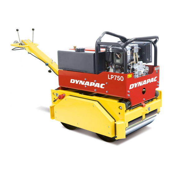
The LP 650/750 is a forward/reverse running, two-drum roller that is ideal for the compaction of earth
and asphalt compounds. The machine consists of a welded lower frame with a vibrator element located
between the two drums. Transmission to the vibrator element is made with the aid of hydraulic power
and propulsion is also hydraulic via chain drive to the drums. Infinitely regulated speed control
facilitates operation. The machine is equipped with a 56 litre (15 gallon) sprinkler system to permit long
shifts without the need of refilling. The water cock is well protected and easily accessible for the opera-
tor. The water tanks are made of plastic to avoid corrosion and the filler caps are large in order to
facilitate refilling. The lower part of the machine has a small overhang to allow the roller to be run
close to obstructions, eg, walls. The upper part is suspended by four rubber dampers and is secured to
the lower part with safety straps. The engine is fitted with a centrifugal clutch to relieve the hydraulic
system when idling. The machine is also equipped with a safety frame to protect the engine during
transport and work, and the frame is provided with a single-point hoisting bracket for easy loading and
unloading. The handlebar is retractable to facilitate transportation. The machine is equipped with a
dead-man's handle. Electric starter, and push-stop to reduce the danger of crushing, are available as
The machine and its accessories may only be used for their intended purpose. The LP rollers
are designed for operation in well ventilated spaces, as all combustion engine machines.
Duplex Roller
LP 650
LP 750
Operation & Maintenance
ILP650EN1, August 2001
Diesel engine:
Hatz Supra 1D81S
These instructions apply from (S/N):
LP 650: *46502740*
LP 750: *47501199*
optional accessories.
Reservation for changes.
Printed in Sweden.
Advertisement
Table of Contents

Subscribe to Our Youtube Channel
Related Manuals for Dynapac LP 650


Summary of Contents for Dynapac LP 650
- Page 1 LP 650: *46502740* LP 750: *47501199* The LP 650/750 is a forward/reverse running, two-drum roller that is ideal for the compaction of earth and asphalt compounds. The machine consists of a welded lower frame with a vibrator element located between the two drums. Transmission to the vibrator element is made with the aid of hydraulic power and propulsion is also hydraulic via chain drive to the drums.
-
Page 2: Table Of Contents
State of California to cause cancer, birth defects, and other reproductive harm. Read the entire manual before starting the machine and before any service work. Ensure good ventilation (air extraction) if the engine is run indoors. LP 650/750 — ILP650EN1... -
Page 3: General
There are additional instructions relating to the engine. Please see the manufacturer’s instructions in the engine manual. MACHINE PLATE Fill in all data below, when delivering and commissioning the machine. L000005A ................Engine Model Engine Number LP 650/750 — ILP650EN1... -
Page 4: Safety Instructions (For All Light Products)
Use only original parts. • Dust mask in dusty environments Use only the accessories recommen- • High-visibility clothing ded by Dynapac. If modifications not • Protective gloves approved by Dynapac are carried out, • Protective shoes these could result in serious injury to Avoid wearing loosely fitting clothing that might yourself or other personnel. - Page 5 Use the machine only for the purpose for which it is intended. Make sure you know how to stop the machine quickly in the event of an emer- gency situation. LP 650/750 — ILP650EN1...
- Page 6 In all cases of uncertainty with regard to durability or wear, replace the hoses with new original hoses from Dynapac. Working with battery The battery contains poisonous and corrosive sulphuric acid.
-
Page 7: Driving Near An Edge
ON, and driving speed can all cause the machine to topple even on a smaller slope than specified here. Never leave the machine unattended with the engine running. Max 17° or 30% L000008A Tipping angle on side slopes LP 650/750 — ILP650EN1... -
Page 8: Safety Decals, Location/Description
SAFETY DECALS, LOCATION/DESCRIPTION L000001A LP 650/750 — ILP650EN1... -
Page 9: Safety Decals, Location/Description
Warning - hot surfaces in Diesel "Parking Brake" the engine compartment. Do not touch. Lock the handle during Lifting "ON Brake" transport. point 283743 Compressed spring assem- Securing Use ear bly. Read the service manual. point protectors LP 650/750 — ILP650EN1... -
Page 10: Fuel And Lubricants
Take care not to spill fuel. Service parts P/N Hatz 1D81S Engine air filter element 23 94 23 Engine oil filter 23 93 26 Engine fuel filter 93 76 16 Hydraulic filter 23 96 27 LP 650/750 — ILP650EN1... -
Page 11: Technical Data
The above noise level and vibration values were determined at normal engine speed with vibration on. The machine was placed on an elastic base. During operation these values may differ because of the actual operational conditions. LP 650/750 — ILP650EN1... -
Page 12: Technical Data - Dimensions
TECHNICAL DATA – DIMENSIONS L000002A L000003A LP 650 LP 750 1916 1973 2634 2640 1286 1372 Ø 440 Ø 500 G mm 1195 1283 Accessories Electric starter Electric starter Push-stop Push-stop LP 650/750 — ILP650EN1... -
Page 13: Instruments And Controls
11. Control lamp, oil pressure 4. Parking brake 12. Oil dipstick 5. Locking hook, handle 13. Sight glass, hydraulic fluid 6. Refuelling 14. Shut-off cock, sprinkler 7. Throttle 15. Filler cap, sprinkler 8. Ignition key = Accessories LP 650/750 — ILP650EN1... -
Page 14: Handle Position
The charging and oil pressure lamps must be extinguished during normal operation. If the lamps do not go out, stop the machine and take corrective action. L000025A Warning lamps 1. Oil pressure lamp 2. Charging lamp LP 650/750 — ILP650EN1... -
Page 15: Operation
4. Fill the sprinkler tank (15) with water. L000012A Filling the fuel/sprinkler tank Check operation of the push-stop, parking brake and controls. Ensure that there is no leakage of oil and that all bolted joints are tight. L000018A Function check LP 650/750 — ILP650EN1... -
Page 16: Operation - Manual Start
L000015A Motor Stopping the engine 1. Set the throttle to allow the engine to idle for a minute or so. 2. Move the throttle to the bottom position to stop the engine. L000016A Motor LP 650/750 — ILP650EN1... -
Page 17: Operation - Electric Starter (Accessories)
1. Set the throttle to allow the engine to idle for a minute or so. 2. Move the throttle to the bottom position to stop the engine. 3. Turn the ignition key to zero. L000025A Engine LP 650/750 — ILP650EN1... -
Page 18: Lifting, Transportation And Towing
Use the front and rear towing attachments to lash the machine. Clamp down the roller with the lashing strap (1) in the front and rear of the machine; decals indicate the fixing points. L000007A Roller ready for transportation 1. Lashing strap LP 650/750 — ILP650EN1... -
Page 19: Maintenance - Service Points
Check setting of the scrapers Check level of battery fluid and top up as required (optional) Fill the sprinkler system with water Check for leakage of oil Check that all bolted joints are tight Keep the machine clean LP 650/750 — ILP650EN1... -
Page 20: Maintenance – Service Points
Every 500 hours of operation (Once a year) Item in fig. Maintenance see page Comments Change the fuel filter Change the hydraulic oil Change the hydraulic filter Change the oil in the eccentric element LP 650/750 — ILP650EN1... -
Page 21: Maintenance - Every 10 Hours Of Operation
L000026A Air filter Hydraulic reservoir – Check fluid level Check that the right level of fluid is indicated in the sight glass. Top up as required with hydraulic fluid. L000024A Hydraulic reservoir LP 650/750 — ILP650EN1... -
Page 22: Maintenance – Every 10 Hours Of Operation
This will prevent water from entering the venting hole in the filler cap. This could otherwise cause operational L000011A disturbance, for example, a clogged filter. Washing the machine LP 650/750 — ILP650EN1... -
Page 23: Maintenance - Every 250 Hours Of Operation
5 bar (72 psi) to remove any remaining dust. The filter must be replaced if it is wet or oily. See engine manual. Engine valve clearance – Checking/Adjusting See engine manual. Engine cooler system – Cleaning LP 650/750 — ILP650EN1... - Page 24 3. Tighten the battery terminals. 4. Ensure that the battery is secure. Controls and pivoted joints – Cleaning/Lubrication Clean and lubricate ball-joints, bushes, glide surfaces, etc, to ensure proper function and to prevent corrosion. L000022A Controls LP 650/750 — ILP650EN1...
-
Page 25: Maintenance - Every 500 Hours Of Operation
3. Insert the new filter in the housing and inspect the O-ring in the cover. 4. Screw the cover back on and ensure that there is no leakage. LP 650/750 — ILP650EN1... - Page 26 2. Clean the drain plug (1) and screw back in. L000013A 3. Fill with fresh oil according to specifications. It may Eccentric element be necessary to loosen the water tank above the 1. Drain plug filler plug. LP 650/750 — ILP650EN1...
- Page 28 Dynapac Compaction Equipment AB Box 504, SE-371 23 Karlskrona, Sweden Phone: +46 455 30 60 00 Fax: +46 455 30 60 30 www.dynapac.com...
Need help?
Do you have a question about the LP 650 and is the answer not in the manual?
Questions and answers