
Subscribe to Our Youtube Channel
Related Manuals for Dynapac CA 262 Series


Summary of Contents for Dynapac CA 262 Series
- Page 1 DYNAPAC CA 262/362/512 MAINTENANCE M262EN2 Box 504, SE-371 23 Karlskrona, Sweden Telephone +46 455 30 60 00 Telefax +46 455 30 60 30 www.dynapac.com...
- Page 2 ILF015WO1...
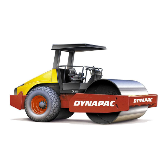
- Page 3 CA 512PD PIN (S/N) *70520512* Dynapac’s medium-range vibratory soil compactors are the CA 262/362 and CA 512. They are available in D (smooth drum) and PD (padfoot) versions, of which the CA 362D and CA 512D are designed for the compaction of rock fill. The PD versions have their major range of application on cohesive material and disintegrated rock.
-
Page 4: Table Of Contents
CONTENTS Page Lubricants and symbols ........... 3 Technical specifications ..........4-7 Maintenance schedule ............. 8 Maintenance measures ..........9, 10 Every 10 hours of operation (Daily) ......11-14 Every 50 hours of operation (Weekly) ...... 15-18 Every 250 hours of operation (Monthly) ....19-23 Every 500 hours of operation (Every three months) 24, 25 Every 1000 hours of operation (Every six months) .. -
Page 5: Lubricants And Symbols
50/50 with water Anti-freeze protection down to about -41°C (-106°F). Other fuel and lubricants are required for operation in extremely high or extremely low ambient temperature. See the “Special instructions” chapter, or consult Dynapac. Engine, oil level Air pressure... -
Page 6: Technical Specifications
TECHNICAL SPECIFICATIONS Weights & dimensions CA262D CA262PD CA362D Operating mass with ROPS, EN500 kg (lbs) 10500 (23,153) 11900 (26,240) 13050 (28,775) Operating mass without ROPS, kg (lbs) 10000 (22,050) 11400 (25,137) 12550 (27,672) Operating mass with cab, kg (lbs) 10500 (23,152) 11900 (26,239) 13050 (28,775) Length, standard-equipped roller, mm (in) - Page 7 TECHNICAL SPECIFICATIONS Vibration data CA262D CA262PD CA362D Static linear load kg/cm (pli) 25,5 (143) – 37,5 (210) Amplitude (High)mm (in) 1,7 (0.066) 1,6 (0.062) 1,7 (0.066) Amplitude (Low)mm (in) 0,8 (0.031) 0,8 (0.031) 0,8 (0.031) Frequency (High amplitude)Hz (vpm) 33 (1980) 33 (1980) 33 (1980) Frequency (Low amplitude)Hz (vpm)
- Page 8 TECHNICAL SPECIFICATIONS Tightening torque Tightening torque in Nm (lbf.ft) for oiled, bright galvanized bolts tightened with a torque wrench. STRENGTH CLASS thread 10.9 12.9 8,4 (6.2) 12 (8.9) 14,6 (10.8) 21 (15.5) 28 (20.7) 34 (21.1) 40 (15.5) 56 (41.3) 68 (25.1) 70 (51.6) 98 (72.3)
- Page 9 TECHNICAL SPECIFICATIONS Vibrations – Drivers seat The vibration values are measured in conformance (ISO 2631) with the driving mode described in EU directive 2000/14/EC on EU equipped machines, on soft polymer material with vibration switched ON and the operator’s seat in transport mode. Whole-body vibration is measured at less than the action value of 0.5 m/s specified in EU directive...
-
Page 10: Maintenance Schedule
MAINTENANCE SCHEDULE 3 4 5 6 7 8 9 39 37 26 25 24 23 22 19 36 35 34 18 17 Fig. 1 Service and maintenance points 1. Radiator grille 14. Scrapers 27. Diesel engine mountings, 4 pcs. 2. Oil level, diesel engine 15. -
Page 11: Maintenance Measures
MAINTENANCE MEASURES The periodic measures should be performed primarily after the specified hours of operation. Use the daily, weekly, etc. time periods only where this is not possible. Remove all dirt before filling, when checking oils and fuel, and when lubricating with oil or grease. - Page 12 MAINTENANCE MEASURES Every 250 hours of operation (Monthly) Item. in Measure See page Comments fig. 1 Check oil level in rear axle/planetary gearing Check oil level in drum gearbox Check oil level in the drum cartridge Clean the radiators 20, 24 Re-tighten bolted joints Applies only to new or reconditioned component...
- Page 13 EVERY 10 HOURS OF OPERATION (Daily) Scrapers – Checking / Adjustment It is important to consider movement of the drum when the machine turns, ie, the scrapers can be damaged or wear of the drum may increase if adjustment is made closer than the values stated.
-
Page 14: Every 10 Hours Of Operation (Daily)
EVERY 10 HOURS OF OPERATION (Daily) CA 262/362/512 Soft scrapers Loosen the screws (2) and adjust to light contact against the drum. Tighten the screws. Fig. 5 Scrapers 1. Scraper blade 2. Screws Circulation of air – Check Ensure that the engine has free circulation of cooling air through the vents in the hood. - Page 15 EVERY 10 HOURS OF OPERATION (Daily) Diesel engine – Check oil level Place the roller on a level surface. Switch the engine off and push in the reserve/ parking brake knob for all checking and adjustments on the roller, unless otherwise specified.
- Page 16 EVERY 10 HOURS OF OPERATION (Daily) Brake function – Check Check operation of the brakes as follows: Drive the roller slowly forward. Push the reserve/parking brake knob (1); the warning lamp on the instrument panel should light and the roller should stop.
- Page 17 EVERY 50 HOURS OF OPERATION (Weekly) Air cleaner – Check/clean Replace or clean the air cleaner’s main filter if the warning lamp on the instrument panel lights up when the diesel engine is operating at full speed. Undo the three locking braces (1). Then pull off the cover (2) and pull out the main filter (3).
- Page 18 EVERY 50 HOURS OF OPERATION (Weekly) Steering joint/Steering cylinders – Lubrication Place the roller on a level surface. Switch the engine off and push in the reserve/parking brake knob for all checking and adjustments on the roller, unless otherwise specified. Allow no one to get near the steering joint when the engine is running.
- Page 19 EVERY 50 HOURS OF OPERATION (Weekly) Tires – Tire pressure Wheel nuts – Tightening Check the tire pressures using a pressure gauge. If the tires are filled with fluid, the air valve (1) must be in the “12 o’clock” position during pumping. The relevant tire pressures are given under the heading “Specifications”.
-
Page 20: Every 50 Hours Of Operation (Weekly)
EVERY 50 HOURS OF OPERATION (Weekly) Strike-off blade – Lubrication (Optional CA262PD) Always lower the blade to the ground be- fore leaving or parking the roller. Make sure that nobody is in the way when operating the blade. Lower the blade. Wipe the nipples clean from grease and dirt, three on each side of the machine. -
Page 21: Every 250 Hours Of Operation (Monthly)
EVERY 250 HOURS OF OPERATION (Monthly) Rear axle differential – Check oil level Never work under the roller with the engi- ne running. Park on a level surface. Block the wheels securely. Wipe clean and remove the level plug (1) and check that the oil level reaches the lower edge of the plug hole. - Page 22 EVERY 250 HOURS OF OPERATION (Monthly) Drum gearbox – Check oil level Wipe clean the area around the plug (1) and then undo the plug. Ensure that the oil level reaches up to the lower edge of the plug hole. Top off with oil to the right level if the level is low.
- Page 23 EVERY 250 HOURS OF OPERATION (Monthly) Drum cartridge Then unscrew the level plug (3) at the bottom of the cartridge until the hole in the middle of the plug becomes visible. Top off with oil through the filling plug (1), until oil begins to run out from the level-plug hole.
- Page 24 EVERY 250 HOURS OF OPERATION (Monthly) Bolted joints – Checking tightening torque Rear axle suspension (2) 330 Nm (243 lbf.ft), oiled. Steering pump against engine (1) 38 Nm (28 lbf.ft). Engine suspension (3). Check that all M12 bolts (x20) are tightened, 78 Nm (57 lbf.ft). Wheel nuts (4).
- Page 25 EVERY 250 HOURS OF OPERATION (Monthly) Battery – Check electrolyte level Make sure there are no open flame in the vicinity when checking the electrolyte level. An explosive gas is formed in the battery during the charging process. Lift up the engine compartment cover and undo the quick-release screws (1).
-
Page 26: Every 500 Hours Of Operation (Every Three Months)
EVERY 500 HOURS OF OPERATION (Every three months) Controls and moving joints – Lubrication Lubricate engine hood hinges (1) and the slide rails of the operator’s seat with grease, other joints and controls with oil. Lubricate the cab hinges with grease. See lubricant specification. - Page 27 EVERY 500 HOURS OF OPERATION (Every three months) Steering chain and Seat bearing – Lubrication Optional on rollers without cab Remember that the chain is a vital part of the steering mechanism. Clean and lubricate the chain (1) between the seat bearing and steering valve with grease.
-
Page 28: Every 1000 Hours Of Operation (Every Six Months)
EVERY 1000 HOURS OF OPERATION (Every six months) Hydraulic fluid filter Place the roller on a level surface. Switch – Change the engine off and push in the reserve/ parking brake knob for all checking and adjustments on the roller, unless otherwise specified. - Page 29 EVERY 1000 HOURS OF OPERATION (Every six months) Fuel tank – Drainage Water and sediment in the fuel tank are removed via the drainage plug in the bottom of the fuel tank. Be very careful during draining. Do not drop the plug or else all the fuel will flow out.
- Page 30 EVERY 1000 HOURS OF OPERATION (Every six months) Rear axle planetary gears – Oil change Position the roller with the plug (1) at its lowest position. Wipe clean, unscrew the plug (1) and drain the oil into a suitable receptacle. The volume is about 2 litres (2.1 qts). Save the oil and deposit it in an approved manner.
- Page 31 EVERY 1000 HOURS OF OPERATION (Every six months) Fresh air filter – Replacement Use a stepladder to reach the filter (1). As an alternative the filter can be reached via the cab window on the right side. Loosen the two screws (2) at the rear of the cab roof. Take down the whole holder and remove the filter insert.
-
Page 32: Every 2000 Hours Of Operation (Yearly)
EVERY 2000 HOURS OF OPERATION (Yearly) Hydraulic reservoir Place the roller on a level surface. Switch the – Fluid change engine off and push in the reserve/parking brake knob for all checking and adjustments on the roller, unless otherwise specified. Danger of being burned when draining hot oil. - Page 33 EVERY 2000 HOURS OF OPERATION (Yearly) Drum gearbox – Changing the oil Place the roller on a level surface with the plugs (1) and (2) as illustrated. Wipe clean, unscrew the plugs (1, 2 and 3) and drain the oil into a suitable receptacle, capacity about 3.5 liters (3.7 qts).
- Page 34 EVERY 2000 OPERATING HOURS (Yearly) Air conditioning (Optional) – Overhaul Regular inspection and maintenance are necessary to ensure satisfactory long-term operation. Clean the condenser element (1) free from dust with the aid of compressed air. Blow from above. The air jet could damage the flanges of the elements if it is too powerful.
- Page 35 EVERY 2000 OPERATING HOURS (Yearly) Compressor – Inspection (Optional) Inspect the compressor and hydraulic motor fastenings. These are located under the cab between the rear sides of the frame. The components are accessible from below. The unit should be run at least five minutes every week, if possible, to ensure lubrication of rubber gaskets in the system.
-
Page 36: Long-Term Storage
LONG-TERM STORAGE For long-term storage (longer than one month), the following instructions should be followed. These instructions apply for storage lasting up to 6 months. Before re-commissioning the roller, the points marked with an asterisk * must be restored. Fig. 60 Protecting the roller from the elements * See the manufacturer’s instructions in the engine Diesel engine... -
Page 37: Special Instructions
SPECIAL INSTRUCTIONS Upon delivery from the factory, the various systems Standard lubricants and other and components are filled with the oils specified see recommended oils lubricant specification and they can be used at ambient temperatures from -10°C to +40°C (14°F - 104°F). A maximum temperature of +35°C (95°F) applies for biological hydraulic fluid. -
Page 38: Electrical System, Fuses, Relays
ELECTRICAL SYSTEM, FUSES, RELAYS Fuses and relays The electrical regulating and control system is protected against overload by 27 fuses and 12 relays. The number depends on how much extra equipment is fitted on the machine. The four fuse boxes (1,2,3,4) and the relays are located behind the lower instrument plate, which can be removed by turning the four quick-screws (5) a ¼-turn. - Page 39 ELECTRICAL SYSTEM, FUSES, RELAYS Fuses in the cab The electric system in the cab is equipped with its own fuse box, located overhead at the front right part of the cab. The figure shows the ampere rating and function of the different fuses.
- Page 40 ELECTRICAL SYSTEM, FUSES, RELAYS Control box The control box (1) automatically regulates preheating of the diesel engine, ie, the box receives its activating signal from a temperature sensor on the engine intake pipe. Fig. 66 Engine compartment 1. Control box for engine preheater 2.
Need help?
Do you have a question about the CA 262 Series and is the answer not in the manual?
Questions and answers