Videx 4000 Series Manual
Codelock module for the gsmpro
Hide thumbs
Also See for 4000 Series:
- Technical manual (80 pages) ,
- Installation instructions manual (44 pages) ,
- Instruction manual (40 pages)
Advertisement
4000 Series
Art. 4903
Codelock Module for the GSMPRO
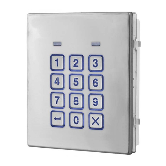
Fig. 1
DESCRIPTION
The module features 12 stainless steel buttons, backlit in blue (keys 0 - 9, ENTER
and CLEAR
), 2 LED's (green LED = data, red LED = status indication)
for progress information during use and programming and a stainless steel or
aluminium front plate, see Fig.1. With two integral relays (RLY1 and RLY2) each
with common (C), normally open (NO) and normally closed (NC) connections
and two switched 0V push to exit inputs SW1 and SW2 to enable the external
triggering of the relays. Key presses are signalled acoustically while each button
press has a tactile feel. Entering the correct code followed by ENTER
activate the relevant relay.
OPERATION
In standby the both LED's on the front of the Art.4903 codelock (Fig.1,
Access Granted: To operate the required relay (RLY1 or RLY2) on the codelock type in the access code for the respective relay, via
), followed by ENTER
the keypad (Fig.1
programmed relay time. The green data LED (Fig.1,
of the relay time.
Access Denied: If an incorrect access code is entered no relay will activate. The codelock will emit a low tone, the green data LED
(Fig.1,
) will flash 4 times followed by a brief pause. The red status LED (Fig.1,
a single beep.
IMPORTANT NOTE: Both relays (RLY1 and RLY2) can also be activated via a push to exit button (configured as a push-to-make
switch) when connected across - and SW1 for RLY1, - and SW2 for RLY2 respectively. It should also be noted that when the relay
time has been set for latching (00) the push to exit button will operate as a "toggle" switch to latch the relay open and latch the
relay closed.
LOCK RELEASE BACK EMF PROTECTION
A varistor must be fitted across the terminals of an AC lock release (see Fig.2) and a diode must be fitted across the terminals of a
DC lock release (see Fig.3) to suppress back EMF voltages. Connect the components to the locks as shown.
Art. 4903 - Installation Instructions
103mm
. Once the correct code has been entered it will operate the respective relay for the
will
and
) will flash once and the codelock will emit a series of beeps for the duration
- 1 -
ENG
4903
STEEL
ALI
HIGH BRASS
Note: Remove MOV
jumper completely
MATTE
when using a relay to
trigger a gate controller.
ON
OFF
RS485 BUS TERMINATION
LEGEND
Data LED (green)
Backlit (blue) key buttons
Status indication LED (red)
Current firmware version (FW X.X)
Back light adjustment jumper (JPL)
RS485 bus termination jumper (JP1)
RS485 bus terminals
PTE terminals (SW1 and SW2)
Relay terminals (RLY1 and RLY2)
Power input terminals
Back EMF protection (JP2 and JP3)
) will be switched OFF.
) will then flash once and the codelock will emit
66251800 - V1.2 - 09/04/19
Advertisement
Table of Contents


Need help?
Do you have a question about the 4000 Series and is the answer not in the manual?
Questions and answers