Videx 4000 Series Manual
Digital to functional interface module/"2 wire bus" system
Hide thumbs
Also See for 4000 Series:
- Technical manual (80 pages) ,
- Installation instructions manual (44 pages) ,
- Instruction manual (40 pages)
Advertisement
Available languages
Available languages
Quick Links
4000 Series
Art. 4203
Digital to functional interface module/"2 Wire bus" system
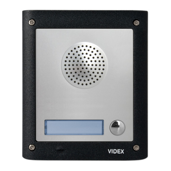
A
C
D
Fig. 1 Front
DESCRIPTION
The Art. 4203 unit is a digital front panel based on a "2 wire"
BUS intercom system that enables the connection of traditional
push buttons. This unit is housed in a single 4000 Series mod-
ule and is available in Mirror Stainless Steel (standard finish) or
anodized aluminium (add /A after the product code). It incor-
porates the functional interface connections from functional to
digital and the speaker unit module with 0, 1, 2 or 4 call buttons.
This device enables the connection of up to 64 functional push
buttons using standard 4000 Series extension module panels
Art. 4842, Art. 4843, Art. 4844, Art. 4845 and relevant double button
version Art. 4842D, Art. 4843D, Art. 4844D and Art. 4845D. The push
buttons already fitted to the module are to be subtracted from the
number of those to be inserted, i.e. 4, 2 or 1 according to the model.
The module built-in buttons, 1, 2 or 4 (Art. 4203-1, Art. 4203-1D or
Art. 4203-2 and Art. 4203-2D) as factory presetting are set as 1
PHONE or 1
and 2
or 1
, 2
st
nd
st
lected by dip-switches 2 and 3. Operating on the wires carried out
from the module, you can set the buttons how you want. If a number
of push buttons greater than 64 is required, more Art. 4203 modules
can be used to have up to 150 buttons with 900 Series, up to 180 but-
tons with 3000 Series (except intercom Art. 316x model) and up to
255 with the low cost intercom Art. 316x..All the modules must be
assembled using the 4000 Series flush or surface mounting units.
The Art. 4203 can work with 900 Series or 3000 Series or with
the new low cost intercom Art. 3161.
Art. 4203
- Installation instructions
3
and 4
of the addresses group se-
nd
rd
th
G
B
L
E
F
Fig. 2 Back
LEGEND
Loudspeaker
A
LEDs
B
Push button 4 - black wire
C
Push button 3 - white wire
D
Push button 2 - red wire
E
Push button 1 - yellow wire
F
AVAILABLE VERSIONS
ID
st
Art. 4203-0
3
Art. 4203-1D
- 1 -
ENG
Black - Button 4
White - Button 3
Red - Button 2
Blue - Common
Yellow - Button 1
Balance
G
Loudspeaker volume
H
Microphone volume
I
8 way dip-switch
L
Jumpers
M
Connection terminals
N
Microphone
O
1
Art. 4203-1
1
66250190 - V2.2 - 28/02/18
H
I
M
O
N
2
1
Art. 4203-2
4
2
3
1
Art. 4203-2D
Advertisement

Related Manuals for Videx 4000 Series


Summary of Contents for Videx 4000 Series
- Page 1 BUS intercom system that enables the connection of traditional Push button 4 - black wire Microphone volume push buttons. This unit is housed in a single 4000 Series mod- Push button 3 - white wire 8 way dip-switch ule and is available in Mirror Stainless Steel (standard finish) or...
- Page 2 4000 Series Art. 4203 Digital to functional interface module/"2 Wire bus" system LEDS CONTROLS The first LED (red), if switched ON, indicates that it is Balance not possible to make a call because a call or a conver- Prevent Larsen effect on bidirectional audio conversation.
- Page 3 4000 Series Art. 4203 Digital to functional interface module/"2 Wire bus" system PROGRAMMING THE DEVICE NUMBER Switch Nr.6 Nr.7 Nr.8 Setting Up Switch Nr.6 Nr.7 Nr.8 Setting Up 1 2 3 4 5 6 7 8 1 2 3 4 5 6 7 8...
- Page 4 4000 Series Art. 4203 Digital to functional interface module/"2 Wire bus" system PUSH BUTTON CONNECTION Dip-Switch n°2=ON Dip-Switch n°2=OFF n°3=OFF n°3=OFF Dip-Switch n°2=ON n°3=ON using 900 Series Dip-Switch n°2=OFF Dip-Switch n°2=ON n°3=ON (only up to n°3=ON (only when 180 if set to work...
- Page 5 4000 Series Art. 4203 Digital to functional interface module/"2 Wire bus" system HOW TO REMOVE/INSERT THE CARD NAME HOLDER • To avoid damage to the module front plate, mask the side that will be in contact with the screwdriver blade; • Insert the screwdriver (flat side) into the card-holder hole as shown in Fig.
- Page 6 Serie 4000 Art. 4203 Modulo d'interfaccia pulsanti tradizionali/sistema "BUS 2 fili" Nero - Pulsante 4 Bianco - Pulsante 3 Rosso - Pulsante 2 Blu - Comune Giallo - Pulsante 1 Fig. 1 Fronte Fig. 2 Retro DESCRIZIONE LEGENDA Altoparlante Regolazione bilanciamento L’...
- Page 7 Serie 4000 Art. 4203 Digital to functional interface module/"2 Wire bus" system REGOLAZIONI Il primo LED (rosso) indica, se acceso, che non è possi- Bilanciamento bile effettuare la chiamata perché è in corso una chi- Previene l’ e ffetto Larsen su conversazione audio bidirezionale. amata o una conversazione (dall’ingresso dal quale si Rif.
- Page 8 Serie 4000 Art. 4203 Digital to functional interface module/"2 Wire bus" system PROGRAMMAZIONE DEL NUMERO DI DISPOSITIVO Switch Nr.6 Nr.7 Nr.8 Impostazione Switch Nr.6 Nr.7 Nr.8 Impostazione 1 2 3 4 5 6 7 8 1 2 3 4 5 6 7 8 1 2 3 4 5 6 7 8 1 2 3 4 5 6 7 8 1 2 3 4 5 6 7 8...
- Page 9 Serie 4000 Art. 4203 Digital to functional interface module/"2 Wire bus" system COLLEGAMENTO PULSANTI Dip-Switch n°2=ON Dip-Switch n°2=OFF n°3=OFF n°3=OFF oppure Dip-Switch n°2=ON n°3=ON con dispositivi Serie 900 Dip-Switch n°2=OFF Dip-Switch n°2=ON n°3=ON (solo fino a n°3=ON 180 se impostato per (solo quando funzionare con altri impostato per...
- Page 10 Serie 4000 Art. 4203 Digital to functional interface module/"2 Wire bus" system RIMOZIONE/INSERIMENTO DEL PORTA-CARTELLINO • Per evitare ammaccature della placca frontale, proteggere il lato che verrà in contatto con la lama del cacciavite utilizzan- do una striscia di nastro isolante; •...
- Page 11 - 11 - 66250190 - V2.2 - 28/02/18...
- Page 12 - 12 - 66250190 - V2.2 - 28/02/18...
- Page 13 - 13 - 66250190 - V2.2 - 28/02/18...
- Page 14 - 14 - 66250190 - V2.2 - 28/02/18...
- Page 15 - 15 - 66250190 - V2.2 - 28/02/18...
- Page 16 - 16 - 66250190 - V2.2 - 28/02/18...
- Page 17 - 17 - 66250190 - V2.2 - 28/02/18...
- Page 18 - 18 - 66250190 - V2.2 - 28/02/18...
- Page 19 - 19 - 66250190 - V2.2 - 28/02/18...
- Page 20 MANUFACTURER VIDEX ELECTRONICS S.P.A. FABBRICANTE Via del Lavoro, 1 FABRICANT 63846 Monte Giberto (FM) Italy FABRICANTE Tel (+39) 0734 631669 FABRIKANT Fax (+39) 0734 632475 www.videx.it - info@videx.it CUSTOMER SUPPORT VIDEX ELECTRONICS S.P.A. UK Customers only: SUPPORTO CLIENTI VIDEX SECURITY LTD www.videx.it - technical@videx.it...
Need help?
Do you have a question about the 4000 Series and is the answer not in the manual?
Questions and answers