
Related Manuals for ATTACK PELH30A


Summary of Contents for ATTACK PELH30A
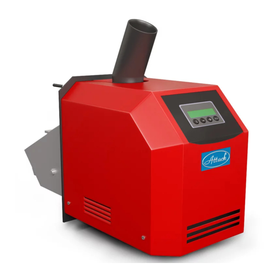
- Page 1 BURNER ® ATTACK PELLET BURNER AUTOMATIC 8–30 kW INSTRUCTIONS FOR USE W W W . A T T A C K . S K...
-
Page 2: Table Of Contents
Possible causes of faults ........................16 Decomposed view ..........................17 Spare parts Codes of spare parts ..................... 18 El. scheme of connection, burner PELH30A ..................19 Endings and connections, fuses ......................20 Accessories............................20 Contact person and electrotechnician ....................21 Service record ............................ -
Page 3: Important Information
Technical description The PELH30A works on basis of the fuel feeding by the principle of falling, when the pellets fall by from the pellet feeder through the inlet hose and the inlet tube on the grate, where they are burned. -
Page 4: Dimensions / Contents Of Delivery
Dimensions / Contents of delivery The PELH30A is delivered in a paper box filled with polysthyrene to improve stability. If the box is damaged, check the burner for possible damage by transport. Claim of the damage by transport has to be registered by a spediteur. -
Page 5: Technical Data
Technical data Model PELH30A Fuel Wood pellets, 6-10 mm Mode 8 – 12 kW; 14 – 30 kW Scale of output 8 - 30 kW, graduated by 2 kW For boilers with the heat chamber up 3 m² Weight 22 kg... -
Page 6: Description Of Function
Description of function NOTE: The PELH30A works with the built-in digital thermostat, resp. with additional room thermostat. In both cases, the burner has to be connected through fuse against boiler overheating. Normal start-up When the thermostat gives instruction to the burner, the ventilator starts and the photocell controls the fire. -
Page 7: How To Use The Pellet Burner
Pellets are supplied into the PELH30A by the external feeder connected to the pellet container. For better function and the most balanced feeding, the feeder should be fixed under the angle of 45°. -
Page 8: Indications On Display
Indications on display Emergency mode PAUS. Nothing in the burner is started, burner waits for the signal from thermostat to start. FC: 0 % Thermostat starts. Step 1 Test blow-through The fan starts to operate and when the photocell recognizes the TEST BLOWING value under 5%, the program continues. -
Page 9: Menu Indications
Menu Indications The burner is in the standby mode. PAUS. FC: 0 % Press the”S” button. Here you can change the burner output. Level 1 = 8 (14) kW, 2 = 10 EFFECT LEVEL (22) kW, 3 = 12 (30) kW. The range and the levels of output are adjustable in the advanced ENTER EXIT... -
Page 10: Production Settings
Production settings Generally accessible menu: Menu Settings Option Adjustable Effect level 1 = 14 kW 1, 2, 3 8-30 kW Pellet-trim 95 % 50-200 % 50 – 200 % Final combustion 90 sec. 10-600 sec. 10 – 26 Not adjustable Not adjustable Advanced menu Random number... -
Page 11: Comeback To The Production Settings
How to change production settings To change the settings, select the required menu/parameters. By pressing the „+“ button, change the actual values. O: ...shows the actual temperature, N: ...can be changed to the new value. It is possible to increase the values by „+“ and to decrease them by „-“. By the „S“ button is the change confirmed and saved. -
Page 12: How To Install The Pellet Burner
How to install the pellet burner The pellet burner PELH30A can be installed only by a qualified, specifically skillful personnel. The door mounted on the boiler from production has to be exchanged for the burner door. Fix the burner on the door by the delivered screws and nuts. Connect the inlet pipe to the pellet feeder under the required angle. -
Page 13: Burner Start
Burner start By turning the boiler´s main switch on, is the burner automatically turned into the stand-by mode. Burner is put into operation by turning the burner´s switch on. Following the demand for heat supply, is the burner ignited and burns pellets, until the thermostat gives instruction to stop. The burner is alternatively controlled by the thermal boiler sensor connected to TS1 inlet on the right upper side of the circuit board. -
Page 14: Cleaning And Maintenance
Cleaning and maintenance It is necessary to clean the burner after every consumption of 2000 kg of pellets. It is based on presumption, that the quality pellets are being burned. Furthermore, it is recommended to sweep exchanger´s parts of the boiler at least twice a month. Clean the pellet inlet into the burner by a brush for bottles or other suitable tool. -
Page 15: Trobleshooting
Trobleshooting Burner turned off. Check, which alarm is displayed. If the display is black and without text, check the thermal fuse of the boiler. If there is no error, probably is just the burner´s thermal fuse turned off. To start again, turn the power supply into the burner off, remove the cover and press the small button between the connections of the fuse of overheating. -
Page 16: Possible Causes Of Faults
Possible causes of faults Error Possible cause Actions to correction code Feeder does not supply Set the pellet ration. enough of pellets. Empty pellet container. Fill the container. Faulty ignition fuse. Replace the fuse. (6.3A). Replace the spiral. (48 Ώ +/- 5%). Faulty ignition spiral. -
Page 17: Decomposed View
Decomposed view... -
Page 18: Spare Parts Codes Of Spare Parts
Spare parts Codes of spare parts H30940A Scraper H30920B Burner grate H30001 Cover of the burner´s hearth H30930A Ignition plate PELH30900 Burning chamber H30980 Ignition coil TS091 Flex-cable H30016E Cabling H30921A Grate clamping H30118C Rod of the end-switch H30009 Pellet brake TH31 Socket H30810... -
Page 19: El. Scheme Of Connection, Burner Pelh30A
El. scheme of connection, burner PELH30A Colour marking of conductors 1 – Main electronics 1 – Brown 2 – Display electronics 2 – Yellow-green 3 - Display 3 – Black 4 – Data cable 4 – Blue 5 – Plug for feeder 6 - Ventilator 7 –... -
Page 20: Endings And Connections, Fuses
Endings and connections, fuses 1. 230 VAC – Phase 2. 230 VAC – Directly earthed conductor 3. 230 VAC – Phase of thermostat 4. Ventilator – Directly earthed conductor 5. Ventilator – Phase 6. Feeder – Directly earthed conductor 7. Feeder – Phase 8. -
Page 21: Contact Person And Electrotechnician
Contact person and electrotechnician Date of installation Installed (by whom): Address-street ZIP Code, City Telephone Cell phone Service record Servised/ Flue gas Date CO ppm Service performed by: Checked temperature... -
Page 22: Advanced Menu
Advanced menu The following data/parameters are adjustable by a qualified person only. All the points of the advanced menu are available by pressing “S”. The actual setting is permanently displayed in the left bottom corner under „O:“ (time/value), whereas the new value is displayed in the right bottom corner under „N“: (time/value). - Page 23 Setting of time of the test blow-through Time of the test blow-through defines the time, within which will TEST BLOWING be the boiler and the chimney ventilated before beginning the combustion (10-100 seconds). ENTER < > EXIT For boilers, at which there is tough to achieve their draught, it is recommended to increase the time of test blow-through.
- Page 24 Setting of the minimum duration of the break between the burn-down and the ignition: This parameter ensures, that it comes to the next burner ignition MIN. PAUSE only after the stated time, not immediately after the burn-down. TIME ENTER < >...
- Page 25 Adjustment of the pellet dosing: = The most important parameter of the control system! Here you FEEDER can set the pellet ration supplied by the feeder at the full operation. ADJUST. To set the pellet ration, you need a plastic sack and a very exact weighing machine.
- Page 26 Settings: The settings made during the installation are stored here, or it is MENU/SETUP possible to reload the production or the installation settings. ENTER Three main options are accessible: Loading of settings, Saving of < > EXIT settings and Production settings. - „Loading of settings“...
-
Page 27: Record About Installation For Warranty Claim
Record about installation for warranty claim Date of installation: 20…..-……-…... Installed in :……..……..………………… Telephone:……………………… Street:…………………………………..Fax:…………………………. ZIP Code and City: ………………….Cell phone:……..………….. …………………………………………… Installed on boiler: Trademark:............ Model:………………………. Pellet burner:……………………………... Serial number:……………….. Pellet feeder: Trademark:……………………………….. Length:……………………….. Serial number:……………………………… Settings of pellet burner: Menu Production Options of... -
Page 29: Record About Installation For Warranty Claim (For Seller)
Record about installation for warranty claim (for seller) Date of installation: 20…..-……-…... Installed in :……..……..………………… Telephone:……………………… Street:…………………………………..Fax:…………………………. ZIP Code and City: ………………….Cell phone:……..………….. …………………………………………… Installed on boiler: Trademark:............ Model:………………………. Pellet burner:……………………………... Serial number:……………….. Pellet feeder: Trademark:……………………………….. Length:……………………….. Serial number:……………………………… Settings of pellet burner: Menu Production... - Page 32 Tel: +421 43 4003 101 • Fax: +421 43 3241 129 • E-mail: kotle@attack.sk Export – tel: +421 43 4003 115 • Fax: +421 43 3241 129 • E-mail: export@attack.sk ATTACK, s.r.o. producer reserves the right to change technical parameters and dimensions of...
Need help?
Do you have a question about the PELH30A and is the answer not in the manual?
Questions and answers