Table of Contents
Advertisement
Quick Links
Advertisement
Table of Contents

Related Manuals for SKF LC502


Summary of Contents for SKF LC502
- Page 1 LC502 control cubicle Original assembly instructions acc. to for use in EC Dir. 2006/42/EC for partly completed machinery ProFlex/MonoFlex/DuoFlex centralized lubrication systems with associated operating instructions Schmierung Fehler starten Fault Start lubrication Version 03...
- Page 2 Masthead If you have technical questions, please contact Electrical voltage/current the following addresses: The door (1) of the LC502 control These original assembly instructions with cubicle (2) must be opened only when associated operating instructions in accordance SKF Lubrication Systems Germany GmbH...
-
Page 3: Table Of Contents
X2, assignment of Lubricant hazards 7. Commissioning the inputs 3. Overview 7.1 Setting parameters of the LC502 4.4.4 MonoFlex centralized lubrication system, control unit 4. Assembly terminal block X2, assignment of the 8. Shutdown and disposal... - Page 4 Page 4 EC Declaration of Incorporation according to Machinery Directive 2006/42/EC, Annex II Part 1 B The manufacturer SKF Lubrication Systems Germany GmbH, plant Hockenheim, 2. Industriestraße 4, DE - 68766 Hockenheim, hereby declares that the partly completed machinery: Designation:...
- Page 5 Explanation of symbols Page 5 Explanation of symbols and signs You will ind these symbols, which warn of Instructions placed directly on the machines/ speciic dangers to persons, material assets, or grease lubrication pump units, such as: the environment, next to all safety instructions Rotation arrow in these operating instructions.
-
Page 6: Assembly Instructions
The control cubicle is referred to in the follow- sons who have been trained, assigned and ing document as the LC502 control cubicle or instructed by the operator of the final product Note that the assembly instructions as the product. -
Page 7: Electric Shock Hazard
Page 7 Assembly instructions Electric shock hazard System pressure hazard Assembly work Electrical connections for the described prod- Lubrication systems are pressurized Work on electrical control cubicles and their during operation. Centralized lubri- uct may only be established by qualified and components should only ever be carried out cation systems must therefore be trained personnel authorized to do so by the... -
Page 8: Lubricants
Regulation EC 1272/2008 may only be used to fill SKF centralized lubrication systems and lubricant supplier. components and deliv-ered and/or distributed The bearings/friction points that require lubri-... -
Page 9: Approved Lubricants
You can request an overview of the lubricant using lubricants that meet the specifications in ronmentally hazardous, flammable substances tests offered by SKF Lubrication Systems the technical data. Depending on the product which require special precautionary measures Germany GmbH from the company's Service design, these lubricants may be oils, fluid during transport, storage, and processing. -
Page 10: Lubricant Hazards
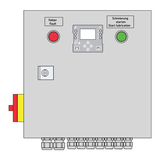
Fault Start lubrication Item Description lubricant leaking out during assembly, operation, maintenance, and repair of 1 LC502 control cubicle centralized lubrication systems. Leaks 2 Basic switch must be sealed off without delay. 3 LC502 control display Lubricant leaking from centralized lubrication 4 Red fault indicator light systems is a serious hazard. -
Page 11: Assembly
The product is mounted in a vertical position. equate distance from sources of heat. Maintain safety clearances and comply The LC502 control cubicle is supplied either as with local regulations for assembly and a separate product or already connected to the accident prevention. -
Page 12: Installing The Lc502 Control Cubicle
(sufficient clearance) for later service length of 15 mm. Open the LC502 control cubicle, place it on the installation surface, and roughly align it and maintenance work (see following page). Fastening material to be provided by the... -
Page 13: Connection Dimensions, Minimum Installation Dimensions
Page 13 Assembly instructions Connection dimensions, minimum installation dimensions 4.2.1 Assembly drawing for LC502 control cubicle Connection dimensions, minimum installation dimensions, Fig. 2 Power supply to control cabinet Power supply to pump motor Input 4 (LC502 control) Input 3 (LC502 control) -
Page 14: Electrical Connection
Danger! improperly connected products. power supply (input voltage) of 230 VAC or Electrical voltage/current 400 VAC 3 -phase . The LC502 control cubicle The power supply to the LC502 control is supplied either as a separate unit or already Danger! -
Page 15: Control Cubicle (Standard Design)
Page 15 Assembly instructions 4.2.2 Control cubicle (standard design) Guide individual cable harnesses as shown on Fig. 2 through the cable glands (conduit thread screw unions) (Fig. 3, item 3) 3 -phase Positioning of connections for control cubicle, types with 24 VDC, 230 VAC, 400 VAC , Fig. -
Page 16: Terminal Block X1, Power Supply
Page 16 Assembly instructions Terminal block X1, power supply 4.3.1 Power supply 24 VDC 4.3.2 Power supply 230 VAC 4.3.3 Power supply 400 VAC 3 -phase 3 -phase 24 VDC 230 VAC 400 VAC Terminal-No. Terminal-No. Terminal-No. Bridge Bridge Bridge Connector Connector Connector... -
Page 17: Connection Of Motor Circuit Breaker (230Vac/400 Vac 3 -Phase )
(230 VAC/400 VAC 3 -phase ) Settings on the motor circuit breaker, Fig. 5 The motor circuit breaker is integrated in the LC502 control cubicle only in the The protection mode of the motor circuit 230 VAC and 400 VAC 3 -phase types. -
Page 18: Assignment Of Terminal Block X2
Page 18 Assembly instructions Assignment of terminal block X2, 4.4.1 DuoFlex centralized lubrication system, terminal block X2, assignment of the inputs inputs with analog pressure sensors 2-wire switch The assignment of the inputs and outputs Terminal diagram X2, 24 VDC/230 V AC/400 VAC •... - Page 19 Page 19 Assembly instructions DuoFlex centralized lubrication system, terminal diagram X2, assignment of the inputs with analog pressure sensors inputs with analog pressure sensors DuoFlex centralized lubrication system, terminal block X2, Terminal-No. Bridge 1kΩ 1kΩ Connector Position Cabletype Cabletype Pressure sensor, line 1 3X0,75 Pressure sensor, line 2 3X0,75...
-
Page 20: Duoflex Centralized Lubrication System, Terminal Block X2, Assignment Of Inputs With Dds50/1
Page 20 Assembly instructions 4.4.2 DuoFlex centralized lubrication system, terminal block X2, assignment of inputs with DDS50/1 Terminal diagram X2, 24 VDC/230 VAC/400 VAC 2-wire switch Terminal block X2 (400V, 230V, 24V) • Switches, buttons, etc. (machine contact) • Cycle switch (2-wire cycle switch only) Input Function 2-wire... - Page 21 Page 21 Assembly instructions DuoFlex centralized lubrication system, terminal diagram X2, assignment of inputs with DDS50/1 inputs and outputs with differential-pressure switch DDS50/1 DuoFlex centralized lubrication system, terminal block X2, Terminal-No. Bridge Connector Position Cabletype Cabletype 5G0,75 Differential-pressure switch grge Delay extension 2X0,75 3X0,75...
-
Page 22: Proflex Centralized Lubrication System, Terminal Block X2, Assignment Of The Inputs
Page 22 Assembly instructions 4.4.3 ProFlex centralized lubrication system, terminal block X2, assignment of the inputs Terminal diagram X2, 24 VDC/230 VAC/400 VAC Terminal block X2 (400V, 230V, 24V) Input Function 2-wire 3-wire Analog switch switch sensor Input 1 Cycle switch (+) Not connected Cycle switch (-) Not connected... - Page 23 Page 23 Assembly instructions ProFlex centralized lubrication system, terminal diagram X2, assignment of inputs inputs and outputs ProFlex centralized lubrication system, terminal block X2, Terminal-No. Bridge Connector Position Cabletype Cabletype Cycle switch 1 2X0,75 Cycle switch 2 2X0,75 Delay extension 2X0,75 3X0,75 Fill level...
-
Page 24: Monoflex Centralized Lubrication System, Terminal Block X2, Assignment Of The Inputs With Pressure Switches
Page 24 Assembly instructions 4.4.4 MonoFlex centralized lubrication system, terminal block X2, assignment of the inputs with pressure switches Terminal diagram X2, 24 VDC/230 VAC/400 VAC Terminal block X2 (400V, 230V, 24V) Input Function 2-wire 3-wire Analog switch switch sensor Input 1 Pressure switch (+) Not connected... - Page 25 Page 25 Assembly instructions MonoFlex centralized lubrication system, terminal diagram X2, assignment of inputs with pressure switches inputs MonoFlex centralized lubrication system, terminal block X2, Terminal-No. Bridge Connector Position Cabletype Cabletype Pressure switch, line 1 2X0,75 Pressure switch, line 2 2X0,75 Delay extension 2X0,75...
-
Page 26: Monoflex Centralized Lubrication System, Terminal Block X2, Assignment Of The Inputs With Analog Pressure Sensors
Page 26 Assembly instructions 4.4.5 MonoFlex centralized lubrication system, terminal block X2, assignment of the inputs with analog pressure sensors Terminal diagram X2, 24 VDC/230 VAC/400 VAC Terminal block X2 (400V, 230V, 24V) Input Function 2-wire 3-wire Analog switch switch sensor Input 1 Not connected... - Page 27 Page 27 Assembly instructions MonoFlex centralized lubrication system, terminal diagram X2, assignment of inputs with analog pressure sensors inputs with pressure sensors MonoFlex centralized lubrication system, terminal block X2, Terminal-No. Bridge 1kΩ 1kΩ Connector Position Cabletype Cabletype 3X0,75 Pressure sensor, line 1 Pressure sensor, line 2 3X0,75 Delay extension...
-
Page 28: Terminal Block X3, Outputs, 24 Vdc
Page 28 Assembly instructions Assignment of terminal block X3, 4.5.1 Terminal block X3, outputs, 24 VDC 4.5.2 DuoFlex centralized lubrication sys- outputs tem, terminal block X3, outputs, 230/400 VAC 3 -phase 24 VDC type 3 -phase X3, 24 VDC X3, 230 VAC/400 VAC The fault signal can be programmed as either an NC contact or an NO contact. -
Page 29: Finishing Assembly Work
Finishing assembly work 4.7 Note on the rating plate Tighten the cable glands (conduit thread screw The rating plate on the LC502 control cubicle Control cubicle, Fig. 6 provides important data such as the type unions) (1) and check for leaks and correct... - Page 31 LC502 control cubicle Operating instructions associated with assembly instructions for use in ProFlex/MonoFlex/DuoFlex according to EC Dir. 2006/42/EC for partly completed machinery centralized lubrication systems...
-
Page 32: Safety Instructions
The safety instructions listed in Chapter 1, Caused by the installation of non-original SKF components or SKF spare parts "Safety instructions," of the assembly instruc- tions also apply without restrictions to these Caused by inappropriate usage operating instructions. -
Page 33: Transport, Delivery, And Storage
3. Transport, delivery, and storage Page 33 3. Transport, delivery, and storage SKF Lubrication Systems Germany GmbH products are packaged in accordance with 3.1 Lubrication units 3.3 General notes standard commercial practice according to the regulations of the recipient's country and... -
Page 34: Assembly
The LC502 control cubicle is designed as a cubicle is described in detail in the assembly compact module for simple assembly and con- instructions associated with these operating tains the LC502 control unit as well as all Schmierung Fehler starten... -
Page 35: Display And Control Elements Of The Control Screen
LED for outlet 1 or 2 lights up = pump outlet 1 or 2 is switched on. Lubricant is delivered via the indi- cated line (1 or 2) LC502 control screen 3 = Inputs Indicator for all signal inputs ... - Page 36 Page 36 6. Control and display elements Display and control elements of the control screen Symbol Description Function Operator keys Operator keys For menu selection (navigation) For editing numerical values Operator keys Operator keys for menu selection (navigation) (arrow key up/down/left) Go to the selected menu based on direction of arrow Operator keys for editing numerical values...
-
Page 37: Commissioning
Press the starter button (2) bicle and must be used when programming the control unit. Remove the Plexiglas cover (3) from the LC502 display screen Using the LC502 display screen (4), set the control unit as instructed in the operating... -
Page 38: Shutdown And Disposal
When recommissioning the product, follow the the costs incurred. safety instructions in Chapter 1 of the assembly instructions. It may be necessary to set the parameters of the control unit as instructed in 7.1, "Setting parameters of the LC502 control unit."... -
Page 39: Maintenance
Assembly, maintenance and cubicle are not permissible. Depending on the location where the LC502 repair work may only be performed on Original spare parts and accessories control cubicle is installed, extreme weather... -
Page 40: Changing Defective Fuses
9 10 1112 6-Q2 position 1 2 3 4 5 6 7 8 Open the door of the LC502 control cubicle L1 N PE 1 2 PE PE PE PE 5 6 7 8 1 2 3 4 6-Q1... -
Page 41: Malfunctions
Chapter 1 of these operating instruc- screen vary depending on the lubrication sys- tions and the safety instructions in the tem, so refer to the relevant LC502 assembly accompanying assembly instructions instructions in order to remedy the faults. (Chapter 1). -
Page 42: Commissioning Malfunctions
Page 42 10. Malfunctions 10.2 Commissioning malfunctions Malfunctions Malfunctions Cause Remedy Short circuits Remedy the cause; check fuses F1 and F2, change if necessary Display screen is Power supply is interrupted Check electrical connection provided by the customer blank Check that the basic switch is set to the "ON" position In the case of the 230/400 VAC type: start the program with the "Control On"... -
Page 43: Operational Malfunctions
10. Malfunctions Page 43 10.3 Operational malfunctions Malfunctions Malfunctions Cause Remedy Fault signal for Pressure/cycles not reached within Check the lines for leaks, remedy any leaks pressure build-up/ the predefined monitoring time DuoFlex cycle switch Check the differential-pressure switch, adjust or replace it if nec- essary (red LED is lit) Differential-pressure switch is defective... -
Page 44: Technical Data
Page 44 11. Technical data / 12. Spare parts 11. Technical data 12. Spare parts Characteristics Spare parts Installation Mounting position Vertical, cable terminals pointing downwards Description Order No. Total weight 8.2 kg Electrical data Miniature fuse slow-blow, 2 A (F1) SM-K26030203 Temperature range 0 °C to 60 °C... - Page 46 However, no liability can be accepted for any loss or damage, whether direct, indirect or consequential, arising out of use of the information contained herein. All SKF products may be used only for their intended purpose as described in these assembly in- structions with associated operating instructions. If assembly/operating instructions are sup- plied together with the products, they must be read and followed.
Need help?
Do you have a question about the LC502 and is the answer not in the manual?
Questions and answers