
Subscribe to Our Youtube Channel
Related Manuals for SKF LCG2-A Series


Summary of Contents for SKF LCG2-A Series
- Page 1 Curve Sensor Control Units Operating instructions of Series LCG2-A/LCG2-B for the control of centralized lubrication systems in rail vehicles Version 05...
- Page 2 Page 2 Notes Service Masthead © SKF Lubrication Systems Germany GmbH If you have technical questions, please contact These operating instructions pursuant to EC This documentation is protected by copyright. the following addresses: MachineryDirective 2006/42/EC are an integral SKF Lubrication Systems Germany GmbH re-...
-
Page 3: Table Of Contents
Page 3 Table of contents Table of contents Information concerning Declaration of Conformity 4.2.9 Setting the spray time t 6.2.1 Curve-dependent spraying Explanation of symbols and signs5 LCG2-A01, -A02, -B01, -B02 4.2.10 Setting the pulse voltage range on LCG2-B 6.2.2 Time-dependent spraying 1. -
Page 4: Information Concerning Declaration Of Conformity
DIN EN 50155:2008-03. Annex II Part B, designed for installation in When used in conformity with their intended use, the products supplied by SKF Lubrication machinery/for incorporation with other Notes: machinery to form a machine. Within the Systems Germany GmbH do not reach the limit scope of application of the EC Directive, values listed in Article 3, Para. -
Page 5: Explanation Of Symbols And Signs5
Explanation of symbols Page 5 Explanation of symbols and signs You will ind these symbols, which warn of Instructions placed directly on the machines/ speciic dangers to persons, material assets, or grease lubrication pump units, such as: the environment, next to all safety instructions Rotation arrows Labels for luid connections You are responsible! -
Page 6: Safety Instructions
CLP of the operating instructions. In particular, any Regulation EC 1272/2008 may only be used malfunctions which may affect safety must be to fill SKF centralized lubrication systems and remedied immediately. components and deliv-ered and/or distributed... -
Page 7: Authorized Personnel
1. Safety instructions Page 7 Authorized personnel Electric shock hazard System pressure hazard Only qualified technical personnel may install, Electrical connections for the described prod- Danger! operate, maintain, and repair the products de- uct may only be established by qualified and Lubrication systems are pressurized scribed in the operating instructions. -
Page 8: Transport, Delivery, And Storage
2. Transport, delivery, and storage General information Electronic and electrical devices General notes SKF Lubrication Systems Germany GmbH Ambient conditions: Dry and dust-free The product(s) can be enveloped in plastic products are packaged in accordance with surroundings, storage in well film to provide low-dust storage. - Page 9 Page 9...
-
Page 10: Overview Of Device Series
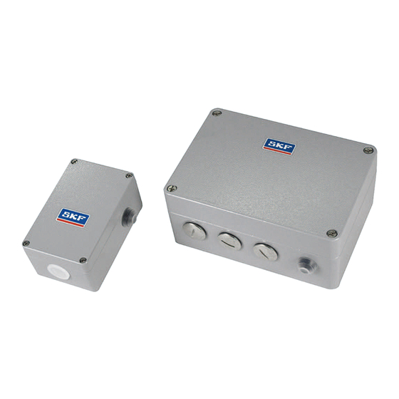
Page 10 3. Overview 3. Overview of device series 3.2 LCG2-A (24 V DC design) 3.1 Distinguishing features Components of the LCG2-A control unit series, Fig. 1 The major features distinguishing the LCG2-A and LCG2-B series are operating voltages, Shown without cover system design, and housing dimensions. - Page 11 3. Overview Page 11 Legend to Fig. 1, Components and function of LCG2-A control unit Item Component Function LED, green Output A1 Valve output A1 (activated) LED, green Output A2 Valve output A2 (activated) LED, yellow Input FG Spray enable (activated) LED, yellow Input VR...
-
Page 12: Lcg2-B (72 V Dc To 110 V Dc Design)
Page 12 3. Overview 3.3 LCG2-B (72 V DC to 110 V DC design) Components of the LCG2-B control unit, Fig. 2 Shown without cover PE M L+ -A1 +A1 -A2 +A2 FG VR DK +P -P ¡ 5 6 7 8... - Page 13 3. Overview Page 13 Legend to Fig. 2, Components and function of LCG2-B control unit Item Component Function Electrical plug connector X1 Valve outputs (PE conductor) Socket for customer wiring Electrical plug connector X2 Operating voltage input Socket for customer wiring Electrical plug connector X3 Valve outputs Socket for customer wiring...
-
Page 14: Design And Function
Page 14 4. Design and function 4. Design and function 4.1 Design The LGC2-A and LCG2-B curve sensor control The significant differences between the units are used to control wheel flange and LCG2-A and LCG2-B series are in their hous- railhead lubrication systems. - Page 15 4. Design and function Page 15 Adjustment elements of LCG2-A, LCG2-B, Fig. 3 Legend to Fig. 3, see page 40 for further information LCG2-A Rotary switch (see Chapter 4.2.2 for description and Chapter 6 for settings) Rotary switch Deactivation, activation, and sensitivity setting of curve sensor DIP switches 1 to 8 Settings for operating mode and other functional parameters - Preselection for time- or distance-dependent spraying...
-
Page 16: Function
Page 16 4. Design and function 4.2 Function Table 2 Software versions Chapter Operating modes/features 4.2.1 Curve sensor special mode 4.2.2 Curve-dependent spraying 4.2.3 Curve-dependent spraying, outside curve (left or right) 4.2.4 Curve-dependent spraying, both sides (left and right) 4.2.5 Adjustable spray interval time for curve-dependent spraying 4.2.7 Time-dependent spraying... -
Page 17: Curve Sensor Special Mode
(SPC) already installed in the vehi- cle, or the SKF IG665+924 control unit (only available in 24 V DC), which comes with addi- tional functions beyond the control unit mod-... -
Page 18: Curve-Dependent Spraying/Calibration
Page 18 4. Design and function 4.2.2 Curve-dependent spraying/calibration The curve sensor control units feature an in- • Enable input FG connected dependent spray cycle is eliminated or ternal sensor that directly detects the turning (switching contact FG closed) overridden. motion of the rail vehicle as it travels through a curve. -
Page 19: Curve-Dependent Spraying, Outside Curve
4. Design and function Page 19 4.2.3 Curve-dependent spraying, 4.2.4 Curve-dependent spraying, 4.2.5 Setting spray interval time t outside curve both sides curve-dependent spraying (software version 01) (software versions 02 and 03) (software versions 01 and 02) In software version 01, only the spray nozzle In software versions 02 and 03, only valve Y1 The spray interval time t for curve-dependent... -
Page 20: Time- Or Distance-Dependent Spraying
Page 20 4. Design and function 4.2.6 Time- or distance-dependent spraying The operating modes and all other functional Spray enable conditions Spray cycle triggering in software versions parameters are set using DIP switches 1 to 8 Setting DIP switch 1 also defines the spray 02 and 03 in accordance with the corresponding tables in enable conditions irrespective of whether the... -
Page 21: Time-Dependent Spraying
4. Design and function Page 21 4.2.7 Time-dependent spraying If time-dependent spraying is to be per- Spray enable condition when using time-de- To prevent time-dependent spraying when the formed, the spraying duration in seconds is pendent spraying: vehicle is stationary, enable input FG must not set using DIP switches 5 to 8 after preselec- •... -
Page 22: Distance-Dependent Spraying
Page 22 4. Design and function 4.2.8 Distance-dependent spraying If distance-dependent spraying is to be per- In order to better distribute the lubricant along If one or both spray enable conditions are no formed, the spraying duration in number of the rail network, a random number generator longer met during a spray cycle, the cycle still distance pulses is set using DIP switches 5 to... -
Page 23: Setting The Spray Time T
4. Design and function Page 23 4.2.10 Setting the pulse voltage range on LCG2-B Example calculation: for example, an excessively short dis- Input +P/-P can be adjusted to the voltage The pulse generator issues 2 pulses per me- tance was preselected and the vehicle range of the distance pulse generator using ter. -
Page 24: Spray Valve Actuation Based On Curve Direction And Direction Of Travel
Page 24 4. Design and function 4.3 Spray valve actuation based on curve direction and direction of travel Spray valve actuation based on curve direction and direction of travel, Fig. 5 Overhead view of rail vehicle Direction of vehicle rotation while traveling through a curve and corresponding effect on ¤... -
Page 25: Assembly
5. Assembly Page 25 5. Assembly General information Setup and installation Only qualified technical personnel may install, The curve sensor control unit should be in- Assembly holes must be made according to operate, maintain, and repair curve sensor stalled in a place protected from contamina- the diagram later in this text (Chapter 5.3.2/ control units of series LCG2-A and LCG2-B . -
Page 26: Installation Of Lcg2-A And Lcg2-B Curve Sensor Control Units
Page 26 5. Assembly Installation of LCG2-A and LCG2-B curve sensor control units Electrical installation See the following figures: Figure 6 for LCG2-A and Figure 7 for LCG2-B. The rules for rail vehicles pursuant to 5.3.1 Mounting equipment DIN EN 50343 must be followed when Unscrew the cover screws (4x) on the cov- installing the electrical lines. -
Page 27: Lcg2-A Mounting Diagram
5. Assembly Page 27 5.3.2 LCG2-A mounting diagram LCG2-A mounting diagram, Fig. 6 Insert ixing screws through the ixing holes „A“ „C“ on the control unit housing and the mounting location; gently tighten washers and self- locking nuts if necessary. Align the control unit housing. -
Page 28: Lcg2-B Mounting Diagram
Page 28 5. Assembly 5.3.3 LCG2-B mounting diagram Electrical connection Danger! LCG2-B mounting diagram, Fig. 7 The mains voltage (supply voltage) must match the speciications on the Cable glands are not included in the delivery! Assembly holes (4x) rating plate of the curve sensor control unit. -
Page 29: Customer Connection Of Lcg2-A
5. Assembly Page 29 Customer connection of LCG2-A Pin assignment on terminal strip X1 Danger! Components of the LCG2-A control unit, Fig. 8 Electrical connections for the product may only be established by qualiied Item Description Protective earth conductor supply and trained personnel authorized to L+ Operating voltage supply do so by the operator in observance of... -
Page 30: Customer Connection Of Lcg2-B
Page 30 5. Assembly 5.6 Customer connection of LCG2-B Components of the LCG2-B control unit, Fig. 9 Pin assignment on terminal strip X2 Pin assignment on terminal strip X4 Item Description Item Description Protective earth conductor supply Input for spray enable Operating voltage supply Input for direction of travel 2 PE M L+... -
Page 31: Electrical Connection Illustration Lcg2-A01; Lcg2-A02; Lcg2-A03
5. Assembly Page 31 5.6.2 Electrical connection illustration LCG2-A01; LCG2-A02; LCG2-A03 Connection illustration LCG2-A01; LCG2-A02; LCG2-A03, Fig. 10 Curve sensor control unit Internal plug connectors X1 internal external... - Page 32 Page 32 5. Assembly Legend to connection diagram for LCG2-A01; LCG2-A02; LCG2-A03 Description Description Control unit type Function Switch Voltage feed, S1 = ON at vehicle start-up Power supply: 24 V DC, 1.0 A All LCG2-A Used only with a compression-loaded lubricant reservoir, Solenoid valve 24 V DC, 11 W (optional) LCG2-A01-000+924...
-
Page 33: Electrical Connection Illustration Lcg2-B01; Lcg2-B02; Lcg2-B03
5. Assembly Page 33 5.6.3 Electrical connection illustration LCG2-B01; LCG2-B02; LCG2-B03 Connection illustration LCG2-B01; LCG2-B02; LCG2-B03, Fig. 11 Internal plug connectors X1 to X4 internal external... - Page 34 Page 34 5. Assembly LCG2-B01; LCG2-B02; LCG2-B03 Legend to connection diagram for Description Description Control unit type Function Switch Voltage feed, S1 = ON at vehicle start-up Power supply: 110 V DC, 0.3 A 72 V DC, 0.4 A LCG2-B01-000+902 Spraying, outside curve Solenoid valve LCG2-B02-000+902...
-
Page 35: Curve Function Of Lcg2-A01/B01
5. Assembly Page 35 Curve function of LCG2-A../B.. curve sensors Curve function, Fig. 12 Overhead view of rail vehicle Direction of vehicle rotation while traveling through a curve and corresponding effect on spray valves Y1 and/or Y2 de- F G H F G H F G P F G P... -
Page 36: Using Curve Sensor Lcg2-A01/ B01
Page 36 5. Assembly 5.7.1 Using curve sensor LCG2-A01/ B01 Curve-dependent spraying, outside curve; ac- Enable input FG tuation of two spray nozzles (left or right) via If only the wheels lying on the outside of the two separate valves (Y1 or Y2) curve are to be sprayed when the vehicle Input FG is used to enable the control unit to travels through curves, direction of travel in-... -
Page 37: Using Curve Sensor Lcg2-A02/A03/B02/B03
5. Assembly Page 37 5.7.2 Using curve sensor LCG2-A02/A03/B02/B03 Curve-dependent spraying, both sides. Switching signal "0" (0 V) = Direction of When the switching signal is “1”, all spray cy- Actuation of two spray nozzles (left and right) travel 1 cles are connected to output A2. -
Page 38: Operation
Page 38 6. Operation 6. Operation Adjustment elements of the curve sensor control units Adjustment elements of LCG2-A, LCG2-B, Fig. 13 Legend to Fig. 13 LCG2-A Rotary switch (see Chapter 4.2.2 for description) Rotary switch Deactivation, activation, and sensitivity setting of curve sensor DIP switches 1 to 8 Settings for operating mode and other functional parameters - Preselection for time- or distance-dependent spraying... - Page 39 6. Operation Page 39 Example of operational sequence for venting lubricant lines, Table 3 Pushbutton DK has several functions: Step DK button Condition Function triggered It can be used to trigger an interim lubrication. actuation To do so, press the DK pushbutton briefly duration (<...
- Page 40 Page 40 6. Operation Adjustment elements, Fig. 14 DIP switches S1 to S8 DIP switches S9/S10 (only on LCG2-B) for setting operating mode These only need to be set if using the distance-dependent spraying function. and all other functional parameters Table E S1 S2 S3 S4 S5 S6 S7 S8 S9 S10...
-
Page 41: Operating Modes Of Curve Sensor Control Units Lcg2-A01, -A02, -B01, -B02
6. Operation Page 41 Operating modes of curve sensor control units LCG2-A01, -A02, -B01, -B02 Curve sensor sensitivity Table cells with a gray background are factory settings. The procedure for determining curve sensor sensitivity is identical on all relevant operating modes. -
Page 42: Lcg2-A01, -A02, -B01, -B02
Page 42 6. Operation 6.2.1 Curve-dependent spraying Table C Table D LCG2-A01, -A02, -B01, -B02 Spraying Switch position Curve Rotary switch cycle sensitivity S5 S6 S7 S8 duration s Degree/s [Switch In this application, DIP switches S9/S10 on position the LCG2-B (Table E) are in the "OFF" position. Curve sensor deactivated 1.90... -
Page 43: Time-Dependent Spraying Lcg2-A01, -A02, -B01, -B02
6. Operation Page 43 6.2.2 Time-dependent spraying Table C Table D LCG2-A01, -A02, -B01, -B02 Spraying Switch position Curve Rotary switch cycle sensitivity S5 S6 S7 S8 duration In this application, DIP switches S9/S10 on s Degree/s [Switch the LCG2-B (Table E) are in the "OFF" position. position... -
Page 44: Lcg2-A01, -A02, -B01, -B02
Page 44 6. Operation Table C Table D 6.2.3 Time- and curve-dependent spraying LCG2-A01, -A02, -B01, -B02 Spraying Switch position Curve Rotary switch cycle sensitivity S5 S6 S7 S8 duration In this application, DIP switches S9/S10 on s Degree/s [Switch the LCG2-B (Table E) are in the "OFF"... -
Page 45: Distance-Dependent Spraying Lcg2-A01, -A02, -B01, -B02
6. Operation Page 45 6.2.4 Distance-dependent spraying Table C Table D LCG2-A01, -A02, -B01, -B02 Number of Switch position Curve Rotary switch pulses sensitivity S5 S6 S7 S8 Table A Degree/s [Switch position Operating Switch position mode S1 S2 Curve sensor deactivated 1125 Table B... -
Page 46: Distance- And Curve-Dependent Spraying Lcg2-A01, -A02, -B01, -B02
Page 46 6. Operation 6.2.5 Distance- and curve-dependent Table C Table D spraying LCG2-A01, -A02, -B01, -B02 Number of Switch position Curve Rotary switch pulses sensitivity S5 S6 S7 S8 Table A Degree/s [Switch position Operating Switch position mode S1 S2... -
Page 47: Operating Modes Of Curve Sensor
6. Operation Page 47 Operating modes of curve sensor Table C Table D control units LCG2-A03, -B03 Spraying Switch position Curve Rotary switch cycle sensitivity 6.3.1 Curve-dependent spraying S5 S6 S7 S8 duration Degree/s [s [Switch In this application, DIP switches S9/S10 on position... -
Page 48: Time-Dependent Spraying
Page 48 6. Operation 6.3.2 Time-dependent spraying Table C Table D In this application, DIP switches S9/S10 on Spraying Switch position Curve Rotary switch the LCG2-A03, -B03 (Table E) are in the cycle sensitivity S5 S6 S7 S8 duration "OFF" position. Degree/s... -
Page 49: Time- And Curve-Dependent Spraying
6. Operation Page 49 6.3.3 Time- and curve-dependent spraying Table C Table D In this application, DIP switches S9/S10 on the Spraying Switch position Curve Rotary switch LCG2-A03, -B03 (Table E) are in the "OFF" cycle sensitivity S5 S6 S7 S8... -
Page 50: Distance-Dependent Spraying
Page 50 6. Operation 6.3.4 Distance-dependent spraying Table C Table D Number of Switch position Curve Rotary switch Table A pulses sensitivity S5 S6 S7 S8 Operating Switch position Degree/s [Switch mode position S1 S2 Curve sensor deactivated 1125 Table B 1700 (design LCG2-B03) Table E Spray time t... -
Page 51: Distance- And Curve-Dependent
6. Operation Page 51 6.3.5 Distance- and curve-dependent Table C Table D spraying Number of Switch position Curve Rotary switch Table A pulses sensitivity S5 S6 S7 S8 Operating Switch position Degree/s [Switch mode position S1 S2 Curve sensor deactivated Table B 1.90 1125... -
Page 52: Commissioning
Chapter 6.1, Table 3. safety instructions in Chapter 2 and the pa- rameter adjustments in Chapter 6.1. The product can also be returned to SKF The curve sensor sensitivity can be set to po- Lubrication Systems Germany GmbH for dis- sition B (0.73°/s) (factory setting) for commis-... -
Page 53: Maintenance And Service
Assembly, SKF Lubrication Systems Germany GmbH maintenance, and repair work may only products are low-maintenance. Only original spare parts from SKF Lu- be performed on products that have However, you should inspect the following at brication Systems Germany GmbH may... -
Page 54: Operational Malfunctions
You can also contact damaged or destroyed by inadvertent other connections) and allow for quick inspec- the Service department of SKF Lubrication electrostatic charge and discharge tion in case of malfunctions. If errors occur, Systems Germany GmbH. - Page 55 10. Operational malfunctions Page 55 Fault analysis and rectification Fault Possible cause Remedy Check power connection and replace No spraying occurs when pushbutton DK is o Curve sensor control unit is not connected actuated to operating voltage back-up fuses (line protection) if necessary ...
- Page 56 Page 56 10. Operational malfunctions Fault analysis and rectification Fault Possible cause Remedy Vent lubricant lines (see Table 3 and sys- Spraying occurs when pushbutton DK is ac- o Lubricant lines are not completely filled tuated but no lubricant discharges from the with lubricant tem documentation) spray nozzle...
- Page 57 10. Operational malfunctions Page 57 Fault analysis and rectification Fault Possible cause Remedy Readjust the sensitivity Curve-dependent spraying is not performed o Vehicle is traveling too slowly for the set curve sensor sensitivity or the curve radius is too large ...
- Page 58 Page 58 10. Operational malfunctions Fault analysis and rectification Fault Possible cause Remedy Check whether the spray enable signal on Distance-dependent spraying is not o Spray enable signal is not activated on in- performed put FG input FG is functioning properly (see 4.2.2 and 4.2.6) ...
-
Page 59: Technical Data
11. Technical data Page 59 11. Technical data 11.1 General characteristics General characteristics LCG2-A LCG2-B General characteristics - Housing Material Aluminum Aluminum Weight 0.50 kg 1.84 kg Dimensions (WxHxD) without cable (80x125x57) mm (200x140x91) mm glands and internal pushbutton DK Fixing screws 2x M4 4x M6... - Page 60 Page 60 11. Technical data General characteristics LCG2-A LCG2-B Ambient conditions Temperature class acc. to DIN EN 50155: 2008-03 Working temperature range -25 °C to 70 °C -25 °C to 70 °C Storage temperature range -40 °C to 85 °C -40 °C to 85 °C Air humidity acc.
- Page 61 11. Technical data Page 61 General characteristics LCG2-A LCG2-B Electrical connection Connection type Spring-loaded terminals Spring-loaded terminals Conductor cross-section flexible without/with ferrule 0.5 to 2.5 mm² 0.5 to 2.5 mm² Stripping length of conductors 10 mm 10 mm Stripping length of conductors when connected to 8 mm additional terminal 179-990-812 or 179-990-813 on mounting rail TS15...
- Page 62 Page 62 11. Technical data General characteristics LCG2-A LCG2-B Spraying duration T for distance-dependent 500 to 123000 pulses, adjustable in 15 500 to 123000 pulses, adjustable in 15 lubrication increments increments Spray interval time t for curve- Software dependent spraying (depending on 01, 02 1.5 s / 3.0 s / 4.5 s / 6.0 s 1.5 s / 3.0 s / 4.5 s / 6.0 s...
-
Page 63: Electrical Characteristics
11. Technical data Page 63 11.2 Electrical characteristics Electrical characteristics LCG2-A LCG2-B Power supply L+/ M Rated voltage U 24 V DC 72 V to 110 V DC Minimum voltage 0.7 x U 0.7 x U Rated operating voltage 1.15 x U 1.15 x U Maximum voltage 1.25 x U... - Page 64 Page 64 11. Technical data Electrical characteristics LCG2-A LCG2-B Outputs A1, A2 Switching output Solid state switch, high-side Solid state switch, high-side Output voltage U Operating voltage minus voltage drop Operating voltage minus voltage drop Voltage drop U Approx. 70 mV @ I = 5 A ≤...
- Page 65 11. Technical data Page 65 Electrical characteristics LCG2-A LCG2-B Inputs FG, VR, DK Input voltage 24 V DC 72 V to 110 V DC Input current Approx. 8 mA Approx. 2.7 mA to 4.2 mA Input impedance Approx. 3.3 kΩ 26 kΩ...
- Page 66 Page 66 11. Technical data Electrical characteristics LCG2-A LCG2-B Signal "1" level ≥ 2 V ≥ 15 V / ≥ 2 V Signal "0" level ≤ 1 V ≤ 10 V / ≤ 1 V Pulse duty factor Max. pulse frequency 2 kHz 300 Hz Spray enable frequency...
- Page 67 Page 67...
- Page 68 However, no liability can be accepted for any loss or damage, whether direct, indirect, or consequential, arising out of use of the information contained herein. All SKF products may be used only for their intended purpose as described in these operating instructions with associated operating instructions. If assembly/operating instructions are supplied together with the products, they must be read and followed.
Need help?
Do you have a question about the LCG2-A Series and is the answer not in the manual?
Questions and answers