Table of Contents
Advertisement
Quick Links
Advertisement
Table of Contents

Subscribe to Our Youtube Channel
Related Manuals for FISCHER DE45 R/S Series


Summary of Contents for FISCHER DE45 R/S Series
- Page 1 Ex nA IIC T4 Gc Ex tc IIIB T125 °C Gc Operating manual DE45 ... R/S Digital differential pressure switch / transmitter with colour-change LCD for explosive areas Dust explosion protection zone 22, dry dusts Gas explosion protection zone 2, gases and vapors...
- Page 2 Great care was taken when compiling the texts and illustrations; Nevertheless, errors cannot be ruled out. The company FISCHER Mess- und Regeltechnik GmbH will not accept any legal responsibility or liability for this.
-
Page 3: Table Of Contents
FISCHER Mess- und Regeltechnik GmbH Table of Content Table of Content 1 Safety instructions......................4 1.1 General........................... 1.2 Personnel Qualification ......................1.3 Risks due to Non-Observance of Safety Instructions............. 1.4 Safety Instructions for the Operating Company and the Operator ......... -
Page 4: Safety Instructions
1 | Safety instructions FISCHER Mess- und Regeltechnik GmbH 1 Safety instructions 1.1 General This operating manual contains basic instructions for the installation, operation and maintenance of the device that must be followed without fail. It must be read by the installer, the operator and the responsible specialist personnel be- fore installing and commissioning the device. -
Page 5: Unauthorised Modification
FISCHER Mess- und Regeltechnik GmbH Safety instructions | 1 • evident damage to the instrument • failure of the electrical circuits • longer storage outside the approved temperature range. • considerable strain due to transport Repairs may be carried out by the manufacturer only. -
Page 6: Pictogram Explanation
1 | Safety instructions FISCHER Mess- und Regeltechnik GmbH 1.8 Pictogram explanation DANGER Type and source of danger This indicates a direct dangerous situation that could lead to death or serious injury (highest danger level). 1. Avoid danger by observing the valid safety regulations. -
Page 7: Product And Functional Description
FISCHER Mess- und Regeltechnik GmbH Product and functional description | 2 2 Product and functional description 2.1 Use as intended The DE45 is a multi-functional switching unit with an optional transmitter output. It is suitable for measuring overpressure, under-pressure and differential pres- sure in gaseous media. -
Page 8: Part Designations
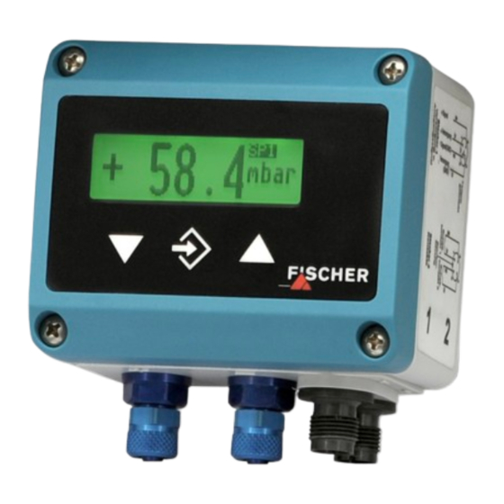
2 | Product and functional description FISCHER Mess- und Regeltechnik GmbH 2.2 Part designations Fig. 1: Part designations Membrane keyboard M12 connector 2 (4-pin, male) LC display M12 connector 1 (5-pin, male) Casing lid Process connection (-) Lower part of casing Process connection (+) 2.3 Function diagram... -
Page 9: Design And Mode Of Operation
FISCHER Mess- und Regeltechnik GmbH Product and functional description | 2 2.4 Design and mode of operation The device is based on a piezo-resistive sensor element that is suitable for measuring overpressure, underpressure and differential pressure. The pres- sures to be compared directly act on a silicon diaphragm equipped with piezo- resistive resistors. -
Page 10: Installation
3 | Installation FISCHER Mess- und Regeltechnik GmbH 3 Installation 3.1 General The device is designed for installation onto flat assembly plates. For screw con- nection to the assembly plate, the device features four assembly bores on its back, which can be used for Ø 3.5 mm tapping screws. -
Page 11: Electrical Connection
FISCHER Mess- und Regeltechnik GmbH Installation | 3 If the pressure sensing lines are already pressurised at the time of commission- ing, zero-point control and adjustment cannot be performed. In such cases, the device should be only connected to the mains without the pressure sensing lines. - Page 12 3 | Installation FISCHER Mess- und Regeltechnik GmbH Connector 1: Supply and output signal Pos Description Cable colour Coding A Internal bridge Supply brown -Sig Signal white Supply blue +Sig Signal black n.c. Fig. 5: M12 Plug 5-pin Connector 2: Switching outputs...
-
Page 13: Commissioning
FISCHER Mess- und Regeltechnik GmbH Commissioning | 4 4 Commissioning 4.1 General All electrical supply, operating and measuring lines, and the pressure connec- tions must have been correctly installed before commissioning. All supply lines are arranged so that there are no mechanical forces acting on the device. - Page 14 4 | Commissioning FISCHER Mess- und Regeltechnik GmbH 4.2.1 Keyboard Fig. 10: Operating keys [LC display] Page down menu Reduce value Call up menu Save value Page up menu Increase value The individual menu items and parameters can be displayed using the buttons þ...
-
Page 15: Menu Levels
FISCHER Mess- und Regeltechnik GmbH Commissioning | 4 4.3 Menu levels The menu levels are structured as follows: Menu level Output Quit Reception Menu Level Switch points Menu Level Input Menu Level Measuring Menu Level Output Menu Level Function Menu Level... - Page 16 4 | Commissioning FISCHER Mess- und Regeltechnik GmbH 4.3.1 Menu Level Switch points Parameter name Description Value range SP1 On Switch point 1 On MRS-50% … MRE+50% SP1 Off Switching point 1 off MRS-50% … MRE+50% SP1 Delay Switching point 1 delay 0…1800 s...
- Page 17 FISCHER Mess- und Regeltechnik GmbH Commissioning | 4 4.3.2 Menu Level Input Parameter name Description Value range Absorption Attenuation, damping 0…100 s Offset corr. Offset correction ⅓ basic measuring range Zero-pt. wind. Zero-point window ⅓ basic measuring range If there are unsteady pressure readings during operation, you can use the para-...
- Page 18 4 | Commissioning FISCHER Mess- und Regeltechnik GmbH 4.3.3 Menu Level Measuring Parameter name Description Value range MB start Measuring range start Basic measuring range MB end Measuring range end Basic measuring range Unit Measuring range unit bar, mbar, Pa, kPa,...
- Page 19 FISCHER Mess- und Regeltechnik GmbH Commissioning | 4 4.3.4 Menu Level Output Parameter name Description Value range min. output min. output 0.0 … 21.0 mA or max. output max. output 0.0 … 11.0 V Error signal Measuring range unit The parameters min.
- Page 20 4 | Commissioning FISCHER Mess- und Regeltechnik GmbH Tables function This function allows free adjustment of the input variable to the display and out- put via a table with up to 30 support points. A value pair comprising a measured value and display value is issued for every support point.
- Page 21 FISCHER Mess- und Regeltechnik GmbH Commissioning | 4 Value pair +14,6 mbar +8,6 % +0,0 ... +100,0 mbar 1 input mark (value flashes) 2 allowed range of values Fig. 13: Value pair Value pair 2 Start 100.0 Measuring range Fig. 14: Table function (example)
- Page 22 4 | Commissioning FISCHER Mess- und Regeltechnik GmbH 4.3.6 Menu Level Display The Display menu level is a variable menu whose appearance depends on the value of the colour parameter. In addition to the various colours for the back- ground lighting, there are also two auto-functions with colour switching avail- able.
- Page 23 FISCHER Mess- und Regeltechnik GmbH Commissioning | 4 Basic measuring range Fig. 15: Function Auto1 MB-start Measuring range start Red-Gr. switch. Red-green switching Gr-Red switch. Green-red switching MB-end Measuring range end The parameter Hysteresis can be used to prevent fast and unwanted colour changes.
- Page 24 4 | Commissioning FISCHER Mess- und Regeltechnik GmbH Auto2: Colour-change red-yellow-green In the Auto 2 mode with the automatic colour switchover, it is possible to enter the required switch thresholds "red-yellow switchover", "yellow-green switchover", green-yellow switchover, "yellow-red switchover". The switching thresholds can be moved within the measuring range. The series of switch points cannot be altered.
- Page 25 FISCHER Mess- und Regeltechnik GmbH Commissioning | 4 Example The parameter Colour is set to Auto2. Only the green, yellow and red ranges are required here. To fade out the lower ranges red and yellow, the switch thresholds "red-yellow switching" and "yellow-green switching" are set to the start of the measuring range.
- Page 26 4 | Commissioning FISCHER Mess- und Regeltechnik GmbH 4.3.7 Menu Level System Parameter name Description Value range Language Language change DE, EN, FR, ES, IT,PT,HU Software Info Information about the software Device type, serial number, firmware version Config. Info Information about the configur-...
- Page 27 FISCHER Mess- und Regeltechnik GmbH Commissioning | 4 NOTICE Delivery condition If the user has not yet saved a configuration, the default values (status on deliv- ery) are loaded. In this case, any measuring range spreads or switch points are reset and the device needs to be newly configured.
-
Page 28: Maintenance
5 | Maintenance FISCHER Mess- und Regeltechnik GmbH 5 Maintenance 5.1 Maintenance The instrument is maintenance-free. We recommend the following regular in- spection to guarantee reliable operation and a long service life: • Check the function in combination with downstream components. -
Page 29: Technical Data
FISCHER Mess- und Regeltechnik GmbH Technical data | 6 6 Technical data Please also observe the order code here. 6.1 Input variables Measuring variable: Differential pressure for gas-like media Measuring Range Stat. operating Bursting pressure max. pressure mbar mbar mbar 0…4... -
Page 30: Auxiliary Energy
6 | Technical data FISCHER Mess- und Regeltechnik GmbH 6.3 Auxiliary energy Rated Voltage 24 V AC/DC Admissible operating voltage = 12…32 V AC/DC Power consumption Typ. 2 W / Max. 3 W WARNING Supply circuit A CE-conform mains adapter with a slow 200 mA fuse only may be used in the power supply circuit. -
Page 31: Application Conditions
FISCHER Mess- und Regeltechnik GmbH Technical data | 6 Measurement TK zero-point TK span range [% FS/10K] [% FS/10K] mbar typ. max. typ. max. 0…60 0…100 0…160 0…250 ±2.5 ±4 ±6 ±10 ±16 ±25 ±40 ±60 ±100 With reference to the basic measuring range (FS), Compensation range 0..60°C. - Page 32 6 | Technical data FISCHER Mess- und Regeltechnik GmbH Wall mounting Model for zone 2 Wall mounting plate Rear view 70.5 without wall mounting plate 71.5 Hose screw connection M12 plug connection Connector 2 Connector 1 4x boreholes for for 6 or 8 mm hose sheet metal screw Ø3.5...
-
Page 33: Display And Operating Interface
FISCHER Mess- und Regeltechnik GmbH Technical data | 6 6.7 Display and operating interface Display 4...6-digit LCD, full graphic, colour backlighting Programming Damping 0.0 … 100.0 s (jump response time 10 / 90 %) Switch output Switch-off point, switch-on point, response time (0...1800s), function (NC / NO contact) -
Page 34: Order Codes
7 | Order Codes FISCHER Mess- und Regeltechnik GmbH 7 Order Codes Code no. 10 11 12 13 14 15 17 18 19 20 21 Type unused [1.2] Measuring range 0 … 4 mbar 0 … 6 mbar 0 … 10 mbar 0 …... - Page 35 FISCHER Mess- und Regeltechnik GmbH Order Codes | 7 [1.2] Measuring range 0 … 1 kPa 0 … 1.6 kPa 0 … 2.5 kPa 0 … 4 kPa 0 … 6 kPa 0 … 10 kPa -1 … +1 kPa -1.6 …...
-
Page 36: Device Specification
7 | Order Codes FISCHER Mess- und Regeltechnik GmbH 7.1 Device specification [17] (Code no.) Use in Zone 2 - Risk from gases and vapours II 3G Ex nA IIC T4 Gc Use in Zone 22 - Risk from dust II 3D Ex tc IIIB T125°C Dc... -
Page 37: Attachments
FISCHER Mess- und Regeltechnik GmbH Attachments | 8 8 Attachments 8.1 EC Declaration of conformity Fig. 19: CE_EN_DE45_LCD_ATEX BA_EN_DE45_ATEX_LCD 37/40... - Page 38 8 | Attachments FISCHER Mess- und Regeltechnik GmbH 8.2 UKCA Declaration of Conformity Fig. 20: UKCA_EN_DE45_LCD_ATEX 38/40 BA_EN_DE45_ATEX_LCD...
- Page 39 FISCHER Mess- und Regeltechnik GmbH Attachments | 8 8.3 EAC declaration Fig. 21: EAC_RU_DE BA_EN_DE45_ATEX_LCD 39/40...
- Page 40 Mess- und Regeltechnik GmbH Bielefelder Str. 37a D-32107 Bad Salzuflen Tel. +49 5222 974-0 Fax +49 5222 7170 www.fischermesstechnik.de info@fischermesstechnik.de Technische Änderungen vorbehalten. Subject to technical changes. Sous réserve de modifications techniques.
Need help?
Do you have a question about the DE45 R/S Series and is the answer not in the manual?
Questions and answers