Table of Contents
Advertisement
Quick Links
Advertisement
Table of Contents

Subscribe to Our Youtube Channel
Related Manuals for FISCHER ECO-LINE DE80


Summary of Contents for FISCHER ECO-LINE DE80
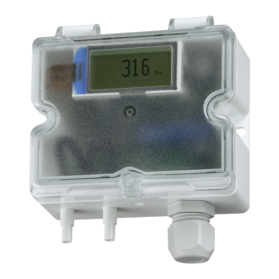
- Page 1 Modbus Operating manual DE80 Differential pressure transmitter ECO-LINE ®...
- Page 2 Great care was taken when compiling the texts and illustrations; Nevertheless, errors cannot be ruled out. The company FISCHER Mess- und Regeltechnik GmbH will not accept any legal responsibility or liability for this.
-
Page 3: Table Of Contents
FISCHER Mess- und Regeltechnik GmbH Table of contents Table of contents 1 Safety instructions ......................4 1.1 General........................... 1.2 Personnel Qualification......................1.3 Risks due to Non-Observance of Safety Instructions ............. 1.4 Safety Instructions for the Operating Company and the Operator ......... -
Page 4: Safety Instructions
1 | Safety instructions FISCHER Mess- und Regeltechnik GmbH 1 Safety instructions 1.1 General This operating manual contains basic instructions for the installation, operation and maintenance of the device that must be followed without fail. It must be read by the installer, the operator and the responsible specialist personnel be- fore installing and commissioning the device. -
Page 5: Safe Working Practices For Maintenance And Installation Work
FISCHER Mess- und Regeltechnik GmbH Safety instructions | 1 1.7 Safe working practices for maintenance and installation work The safety instructions given in this operating manual, any nationally applicable regulations on accident prevention and any of the operating company's internal work, operating and safety guidelines must be observed. -
Page 6: Product And Functional Description
2 | Product and functional description FISCHER Mess- und Regeltechnik GmbH 2 Product and functional description 2.1 Delivery scope ® • Differential pressure transmitter DE80 ECO-LINE version as stated on the type plate • Operating Manual • Closing screw for degree of protection IP65 •... -
Page 7: Design And Mode Of Operation
FISCHER Mess- und Regeltechnik GmbH Product and functional description | 2 2.4 Design and mode of operation The device is based on a piezo-resistive sensor element that is suitable for measuring overpressure, under-pressure and differential pressure. The pres- sures to be compared have a direct effect on a silicon membrane equipped with a measuring bridge. - Page 8 2 | Product and functional description FISCHER Mess- und Regeltechnik GmbH Electrical connection is made via an M16 x 1.5 cable screw connection with an internal terminal strip. Terminal strip Cable screw connection M16 x 1.5 Fig. 4: Electric connections 2.5.1 Type plate This type plate serves as an example of the information that is stated.
-
Page 9: Assembly
FISCHER Mess- und Regeltechnik GmbH Assembly | 3 3 Assembly 3.1 General The device is intended for mounting on level walls and mounting plates. For this purpose, the device has two mounting holes on the side. Locking srew Latch Mounting hole 2... -
Page 10: Electrical Connection
3 | Assembly FISCHER Mess- und Regeltechnik GmbH 3.3 Electrical connection • By authorized and qualified specialized personnel only. • When the device is connected, national and international electrotechnical regulations must be observed. • Disconnect the system from the mains before electrically connecting the device. - Page 11 FISCHER Mess- und Regeltechnik GmbH Assembly | 3 3-conductor with switch output DE80 Power supply Δp +Aout 1 24 V AC/DC Output 1 2 3 4 5 6 7 Fig. 11: Electrical connection of a 3-conductor with switch output 3-conductor with Modbus...
-
Page 12: Start-Up
4 | Start-up FISCHER Mess- und Regeltechnik GmbH 4 Start-up 4.1 General All electrical supply, operating and measuring lines, and the pressure connec- tions must have been correctly installed before commissioning. All supply lines are arranged so that there are no mechanical forces acting on the device. - Page 13 FISCHER Mess- und Regeltechnik GmbH Start-up | 4 4.3.1.1 Measuring range Pa (kPa) mbar 1 2 3 5 6 7 Basic measuring range 1 mbar / 100 Pa +/- 1 mbar 0 ... 1 mbar +/- 100 Pa 0 ... 100 Pa +/- 0,75 mbar 0 ...
- Page 14 4 | Start-up FISCHER Mess- und Regeltechnik GmbH 4.3.1.2 Output signal • Damping affects the analogue output and display. • DIP switch 2 (symmetry) has no function during root extraction. The meas- uring range is fixed to 'asymmetrical unidirectional' (0...x).
- Page 15 FISCHER Mess- und Regeltechnik GmbH Start-up | 4 4.3.2 Device with Modbus NOTICE! In this section you will learn how to configure a Modbus device. Further information can be found in the Modbus manual. Status LED Zero point button DIP switch...
- Page 16 4 | Start-up FISCHER Mess- und Regeltechnik GmbH 4.3.2.2 Interface S1 S2 S3 Σ Baud rate Binary Decimal 1 1 2 3 4 5 6 7 2400 4800 ON=1 OFF=0 9600 14400 19200 38400 57600 115200 S4 S5 Parity without...
- Page 17 FISCHER Mess- und Regeltechnik GmbH Start-up | 4 Zero point button In order to zero the measured value (zero point correction), the button is briefly pressed in the pressureless state. The yellow status LED flashes 1x long and 2x short as confirmation.
-
Page 18: Servicing
5 | Servicing FISCHER Mess- und Regeltechnik GmbH 5 Servicing 5.1 Maintenance The instrument is maintenance-free. We recommend the following regular in- spection to guarantee reliable operation and a long service life: • Check the function in combination with downstream components. -
Page 19: Technical Data
FISCHER Mess- und Regeltechnik GmbH Technical data | 6 6 Technical data 6.1 General Type designation DE80 Pressure type Differential pressure Measurement principle Piezo-resistive Reference conditions (acc. to IEC 61298-1) Temperature +15 to +25 °C Relative humidity 45 … 75 %... -
Page 20: Measuring Accuracy
6 | Technical data FISCHER Mess- und Regeltechnik GmbH 6.4 Measuring accuracy • Based on the reference temperature, the information only applies within the compensation range. • The measurement error includes linearity, hysteresis and non-repeatability. • Compensation range: 0 … 60 °C. -
Page 21: Auxiliary Energy
FISCHER Mess- und Regeltechnik GmbH Technical data | 6 6.6 Auxiliary energy 3-conductor version/Modbus RTU Nominal voltage 24 V AC/DC Admissible operating voltage U 19.2 V … 28.8 V AC/DC Power consumption < 2W 2-conductor version Nominal voltage 24 V DC Admissible operating voltage U 12 V …... - Page 22 6 | Technical data FISCHER Mess- und Regeltechnik GmbH 6.9.1 Materials Materials of the parts that come into contact with the medium Process connection (housing) Polycarbonate PC Sensor element Silicon Hoses EPDM Materials of the parts that come into contact with the surroundings...
-
Page 23: Order Codes
FISCHER Mess- und Regeltechnik GmbH Order codes | 7 7 Order codes Combination Identification No. 13 14 15 16 Type Measurement range: [1.2] Basic measuring range 1 mbar / 100 Pa Basic measuring range 10 mbar/ 1000 Pa Basic measuring range 50 mbar/ 5000 Pa... -
Page 24: Accessories
7 | Order codes FISCHER Mess- und Regeltechnik GmbH Electrical connection: [11] Cable screw connection Assembly: [12] Wall mounting 7.1 Accessories Connection set To connect the differential pressure transmitter to the ventilation channels com- prising • PVC hose • ABS measuring nozzle including attachment screws. -
Page 25: Attachment
FISCHER Mess- und Regeltechnik GmbH Attachment | 8 8 Attachment Fig. 20: CE_DE_DE80 BA_EN_DE80 25/28... - Page 26 8 | Attachment FISCHER Mess- und Regeltechnik GmbH Fig. 21: UKCA_DE_DE80 26/28 BA_EN_DE80...
- Page 27 FISCHER Mess- und Regeltechnik GmbH Notes BA_EN_DE80 27/28...
- Page 28 Mess- und Regeltechnik GmbH Bielefelder Str. 37a D-32107 Bad Salzuflen Tel. +49 5222 974-0 Fax +49 5222 7170 www.fischermesstechnik.de info@fischermesstechnik.de Technische Änderungen vorbehalten. Subject to technical changes. Sous réserve de modifications techniques.
Need help?
Do you have a question about the ECO-LINE DE80 and is the answer not in the manual?
Questions and answers