
Subscribe to Our Youtube Channel
Related Manuals for FISCHER DE43


Summary of Contents for FISCHER DE43
- Page 1 Modbus Operating manual DE43 Digital 2-channel transmitter for direct connection to bus-capable automation devices...
- Page 2 Great care was taken when compiling the texts and illustrations; Nevertheless, errors cannot be ruled out. The company FISCHER Mess- und Regeltechnik GmbH will not accept any legal responsibility or liability for this.
-
Page 3: Table Of Contents
FISCHER Mess- und Regeltechnik GmbH Table of contents Table of contents 1 Safety instructions ............................ 4 1.1 General .............................. 4 1.2 Personnel Qualification.......................... 4 1.3 Risks due to Non-Observance of Safety Instructions ................ 4 1.4 Safety Instructions for the Operating Company and the Operator............ 4 1.5 Unauthorised Modification ........................ 4... -
Page 4: Safety Instructions
1 | Safety instructions FISCHER Mess- und Regeltechnik GmbH 1 Safety instructions 1.1 General This operating manual is an integral part of the product and therefore needs to be kept close to the instrument in a place that is accessible at all times to the re- sponsible personnel. -
Page 5: Safe Working Practices For Maintenance And Installation Work
FISCHER Mess- und Regeltechnik GmbH Safety instructions | 1 1.7 Safe working practices for maintenance and installation work The safety instructions given in this operating manual, any nationally applicable regulations on accident prevention and any of the operating company's internal work, operating and safety guidelines must be observed. -
Page 6: Product And Functional Description
2 | Product and functional description FISCHER Mess- und Regeltechnik GmbH 2 Product and functional description 2.1 Delivery scope • DE43 digital 2-channel transmitter • Operating Manual 2.2 Equipment versions Assembly Attachment boreholes for tapping screws Wall mounting plate Fig. 1: Wall mounting... -
Page 7: Electrical Connections
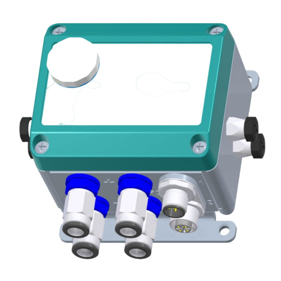
FISCHER Mess- und Regeltechnik GmbH Product and functional description | 2 Electrical connections M12 Plug 1 (male) M12 Plug 2 (female) M8 Bush (female) 2 Digital inputs (3,4) left 4 Digital inputs (1...4) 2 Digital inputs (1,2) right Fig. 4: Electrical connections 2.2.1 Type plate... -
Page 8: Function Diagram
Power Supply Modbus configuration 2.4 Design and mode of operation The basis of the DE43 transmitter comprises two piezoresistive sensor ele- ments. The pressure that is to be measured acts upon a silicone membrane that is equipped with a resistor bridge. The acting pressure causes the membrane to move and therefore a change in resistance. -
Page 9: Assembly
FISCHER Mess- und Regeltechnik GmbH Assembly | 3 3 Assembly 3.1 General The device is designed for installation onto flat assembly plates. For screw con- nection to the assembly plate, the device features four assembly bores on its back, which can be used for Ø 3.5 mm tapping screws. -
Page 10: Electrical Connections
3 | Assembly FISCHER Mess- und Regeltechnik GmbH 3.3 Electrical connections • By authorized and qualified specialized personnel only. • When connecting the unit, the national and international electro-technical regulations must be observed. • Disconnect the system from the mains, before electrically connecting the device. - Page 11 Assembly | 3 3.3.1 Modbus RTU network The DE43 is usually connected in a line network structure as a so-called slave to the Modbus RTU network. Up to 123 bus participants can be operated without an amplifier on one strand NOTICE! Star-shaped networks are not allowed.
- Page 12 < 2 A Fig. 15: Intermediate supply Please note that a DE43 with digital inputs has a higher power draw. If the bus participants are equipped with digital inputs, the number of possible bus parti- cipants of a supply circuit are reduced.
-
Page 13: Start-Up
4.2 Config select The DE43 Transmitter can be configured using an 8-digit DIP switch. To this end, the sealing plug in the front plate needs to be removed. Below this is an 8- pin DIP switch which can be used to configure both the Modbus address and also the interface. - Page 14 4 | Start-up FISCHER Mess- und Regeltechnik GmbH Baud rate 1200 2400 4800 9600 19200 38400 57600 Parity None Identical parity Not identical parity It is not possible to combine identical or non-identical parity with 2 stopbits. Stopbits 1 stopbit 2 stopbits The device needs to be restarted to confirm the settings.
-
Page 15: Modbus Functional Description
FISCHER Mess- und Regeltechnik GmbH Start-up | 4 4.3 Modbus functional description The following describes the Modbus functions that support the DE43 Transmit- ter. The descriptions are initially kept general as explained in the Modbus Pro- tocol Specification and are then supplemented with the unique features of the DE43. - Page 16 (N) is the result of the number of inputs divided by 8. If there is a rest, the number of bytes increases (N=N+1). However, as the DE43 only has a maximum of 4 inputs, only 1 byte is trans- ferred as a response.
- Page 17 1 byte 0x03 Start Address 2 bytes 0x0000 to 0xFFFF Number of registers 2 bytes 0x0001 to 0x007D (1…125) The DE43 Transmitter has precisely 1 Holding Register with the address 0x0000. Data type Description State Unsigned Integer Pressure sensor Sensor error...
- Page 18 Function Code 1 byte 0x04 Start Address 2 bytes 0x0000 to 0xFFFF Number of registers 2 bytes 0x0001 to 0x007D (1…125) The DE43 Transmitter has 3 Input Registers. Reg.No. Address Data type Description Unit Contents 0x0000 Integer Measured value channel Measured...
- Page 19 FISCHER Mess- und Regeltechnik GmbH Start-up | 4 4.3.6 Function code 0x2B/0x0E: Device Identification This Function Code is used to read certain information about identification of the unit. The following object types are used in the FISCHER units: Object ID Object Name Type Category...
- Page 20 4 | Start-up FISCHER Mess- und Regeltechnik GmbH The response comprises several bytes with status information followed by a list Response with the requested object information. List Byte 0x2B 0x0E DevID Conf Follow Next ObjID ObjID Object 0 Object N...
-
Page 21: Led Flash Codes
The LED does not shine green LED Red LED Description The DE43 is ready for operation Flash The DE43 sends an answer to the master via the Modbus 1 x long Pressure sensor 1: 1 x short Error reading the sensor signal... -
Page 22: Servicing
5 | Servicing FISCHER Mess- und Regeltechnik GmbH 5 Servicing 5.1 Maintenance The instrument is maintenance-free. We recommend the following regular in- spection to guarantee reliable operation and a long service life: • Check the function in combination with downstream components. -
Page 23: Technical Data
FISCHER Mess- und Regeltechnik GmbH Technical data | 6 6 Technical data 6.1 General General information Type designation DE43 Pressure type Differential pressure, relative pressure Measurement principle Piezo-resistive Reference conditions (acc. to IEC 61298-1) Temperature +15 … +25 °C Relative humidity 45 …... -
Page 24: Auxiliary Energy
6 | Technical data FISCHER Mess- und Regeltechnik GmbH Pre-set data format Baud rate 9600 Baud Parity None Stopbit Supported Modbus functions 0x02 Read Discrete Inputs 0x03 Read Holding Registers 0x04 Read Input Registers 0x2B / 0x0E Read Device Identification For more information about this, please refer to the operating instructions and online http://www.modbus.org/docs/Modbus_Application_Protocol_V1_1b3.pdf. - Page 25 FISCHER Mess- und Regeltechnik GmbH Technical data | 6 6.6.2 Materials Housing Polyamide PA 6.6 Media-contacting material Silicon, PVC, aluminium, brass 6.6.3 Dimensional drawings M12 Plug 1 M12 Plug 2 70.5 61.5 CK Screw connection Pneumatic plug connection Digital inputs E1 ... E4...
-
Page 26: Order Codes
7 | Order codes FISCHER Mess- und Regeltechnik GmbH 7 Order codes Code no. 10 11 12 2 M M Type Measuring range channel 1: [1.2] [Pa] 0 … 400 0 … 600 0 … 1000 0 … 1600 0 … 2500 Pa -250 …... - Page 27 FISCHER Mess- und Regeltechnik GmbH Order codes | 7 Digital inputs: M8 round plug connector 3-pin, female Without digital inputs Two digital inputs (E3, E4) left Two digital inputs (E1, E2) right Four digital inputs (E1, E2) right and (E3, E4) left...
-
Page 28: Attachments
8 | Attachments FISCHER Mess- und Regeltechnik GmbH 8 Attachments Fig. 23: CE_DE_DE43 28 / 28 BA_EN_DE43...
Need help?
Do you have a question about the DE43 and is the answer not in the manual?
Questions and answers