
Related Manuals for FISCHER DE49 A Series


Summary of Contents for FISCHER DE49 A Series
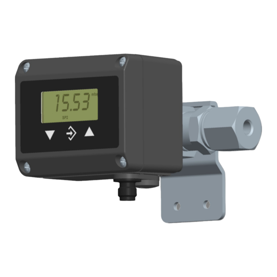
- Page 1 Operating manual DE49 ## A Digital differential pressure transmitter with external sensor for explosive areas Dust explosion protection zone 21 and 22, dry dusts Gas explosion protection zone 1 and 2, gases and vapors...
- Page 2 Great care was taken when compiling the texts and illustrations; Nevertheless, errors cannot be ruled out. The company FISCHER Mess- und Regeltechnik GmbH will not accept any legal responsibility or liability for this.
-
Page 3: Table Of Contents
FISCHER Mess- und Regeltechnik GmbH Table of contents Table of contents 1 Safety guidelines......................4 1.1 General........................... 1.2 Personnel Qualification ......................1.3 Risks due to Non-Observance of Safety Instructions............. 1.4 Safety Instructions for the Operating Company and the Operator ......... -
Page 4: Safety Guidelines
1 | Safety guidelines FISCHER Mess- und Regeltechnik GmbH 1 Safety guidelines 1.1 General This operating manual contains basic instructions for the installation, operation and maintenance of the device that must be followed without fail. It must be read by the installer, the operator and the responsible specialist personnel be- fore installing and commissioning the device. -
Page 5: Unauthorised Modification
FISCHER Mess- und Regeltechnik GmbH Safety guidelines | 1 • evident damage to the instrument • failure of the electrical circuits • longer storage outside the approved temperature range. • considerable strain due to transport Repairs may be carried out by the manufacturer only. -
Page 6: Pictogram Explanation
1 | Safety guidelines FISCHER Mess- und Regeltechnik GmbH 1.8 Pictogram explanation DANGER Type and source of danger This indicates a direct dangerous situation that could lead to death or serious injury (highest danger level). 1. Avoid danger by observing the valid safety regulations. -
Page 7: Product And Functional Description
FISCHER Mess- und Regeltechnik GmbH Product and functional description | 2 2 Product and functional description 2.1 Scope of delivery • Digital differential pressure transmitter with external sensor • User Manual 2.2 Intended use The differential pressure transmitter DE49##A###BH00MW allows the meas- urement of under-pressure, over-pressure and differential pressure in liquid and gaseous media. -
Page 8: Function Diagram
2 | Product and functional description FISCHER Mess- und Regeltechnik GmbH 2.3.1 Type plate The presented type plates serve to show an example of the information shown. The data shown is purely fictive, but does correspond to the actual conditions. -
Page 9: Design And Mode Of Operation
FISCHER Mess- und Regeltechnik GmbH Product and functional description | 2 2.5 Design and mode of operation The multifunctional differential pressure transmitter with 2-conductor technology allows the measurement of under-pressure, over-pressure and differential pres- sure in liquid and gaseous media. The basis is a piezoresistive pressure sensor that is attached to a base with glass openings on the inside of a metal case. -
Page 10: Assembly
3 | Assembly FISCHER Mess- und Regeltechnik GmbH 3 Assembly 3.1 General The device is designed for installation onto flat assembly plates or walls. At the factory, the device is calibrated for vertical installation, but the installation position is arbitrary. For any installation positions that are not vertical, the zero- point signal can be corrected via the installed offset correction. -
Page 11: Electrical Connections
FISCHER Mess- und Regeltechnik GmbH Assembly | 3 The pressure lines must be installed at an inclination so that when fluids are measured no air pockets are created or when measuring gases, no water pock- ets are created. If the required inclination is not reached, water or air filters must be installed at suitable places. - Page 12 3 | Assembly FISCHER Mess- und Regeltechnik GmbH 2-conductor circuit Pressure transmitter Intrinsically safe Non-ATEX DE49 barrier supply +Sig Δp -Sig ATEX zone Output signal Input signal Fig. 6: 2L Circuitry Supply and signal power circuit limit values (Ignition protection type intrinsic safety Ex ia IIC) ≤...
-
Page 13: Commissioning
FISCHER Mess- und Regeltechnik GmbH Commissioning | 4 4 Commissioning 4.1 Generalities WARNING Operation in areas at risk of explosion If operated in explosive areas, the electrical data of the unit and the valid local regulations and guidelines for the installation and operation of electrical systems in explosive areas must be observed. - Page 14 4 | Commissioning FISCHER Mess- und Regeltechnik GmbH After setting all parameters, leave the menu as follows: ÿ þ • Use the arrow keys to set the parameter. You will find these at the start and also at the end of the menu.
- Page 15 FISCHER Mess- und Regeltechnik GmbH Commissioning | 4 4.3.3 Margin correction span The parameter is used to correct the measuring range span. The current measurement is shown. Using the arrow keys, this can be changed by up to ±10% of the basic measuring range. Keep the arrow keys pressed until the re- quired value is shown.
- Page 16 4 | Commissioning FISCHER Mess- und Regeltechnik GmbH 4.3.7 Function selection The parameter allows you to select between the following functions: • The device works as a linear transmitter. • causes a rooting of the output signal and the display.
- Page 17 FISCHER Mess- und Regeltechnik GmbH Commissioning | 4 The table is correct if the following applies for all signal values: The value is lar- ger than the previous value. Either larger (rising characteristic curve) or smaller (falling characteristic curve) apply to the pressure values accordingly. No trans- ition from rising to falling characteristic curves or vice versa is allowed.
- Page 18 4 | Commissioning FISCHER Mess- und Regeltechnik GmbH 4.3.9 Reset The function allows all settings to be reset to default values. The default value for this parameter is 0. Enter the value 1 to carry out a RESET. As soon as the configuration mode is...
- Page 19 FISCHER Mess- und Regeltechnik GmbH Commissioning | 4 Function selection • F=0 The device works as a linear transmitter. The parameters marked in red and blue are hidden. • F=1 causes a rooting of the output signal and the display.. The parameters marked in red (dPF, MAF, MEF, MEd) and shown.
- Page 20 4 | Commissioning FISCHER Mess- und Regeltechnik GmbH i g1 lower current limit Define the minimum output signal here (3.5 ... 22.5mA). i g2 upper current limit Define the maximum output signal here (3.5 ... 22.5mA). i er Error signal Define the output signal here (3.5 ... 22.5mA) that should be issued when there is an internal error in the device.
-
Page 21: Servicing
FISCHER Mess- und Regeltechnik GmbH Servicing | 5 5 Servicing 5.1 Maintenance To ensure reliable operation and a long service life, we recommend carrying out the following test on a regular basis: • Check the reading. • Checking the switch function in connection with the downstream compon- ents. -
Page 22: Technical Data
6 | Technical data FISCHER Mess- und Regeltechnik GmbH 6 Technical data 6.1 General Please also observe the order code here. 6.2 Input variables Measuring variable: Differential pressure for gaseous media Measuring ranges Stat. operating pressure Bursting pressure max. 0 … 250 mbar max. -
Page 23: Auxiliary Energy
FISCHER Mess- und Regeltechnik GmbH Technical data | 6 6.6 Auxiliary energy The unit power supply may only be an inherently safe power circuit of the igni- tion protection type 'Ex ia IIC'. Rated Voltage 24v DC Admissible operating 12 … 30 V... - Page 24 6 | Technical data FISCHER Mess- und Regeltechnik GmbH 6.8.1 Dimensional drawings All dimensions in mm unless otherwise stated Pressure compensation M12 plug connection AF27 Hexagonal Process connection (for options see order code) Fig. 11: Dimensional picture 24/36 BA_EN_DE49_A...
-
Page 25: Order Codes
FISCHER Mess- und Regeltechnik GmbH Order Codes | 7 7 Order Codes Code no. 10 11 12 0 M W Type [1.2] Measuring range Static operating pressure 0 … 250 mbar 3 bar 0…1 bar 3 bar EXECUTION Encapsulated sensor... -
Page 26: Accessories
7 | Order Codes FISCHER Mess- und Regeltechnik GmbH 7.1 Accessories Order no. Designation No. of length Poles 06401685 Connection cable with M12 connector 5 pin 06401686 Connection cable with M12 connector 5 pin 06401687 Connection cable with M12 connector... - Page 27 FISCHER Mess- und Regeltechnik GmbH Attachments | 8 BA_EN_DE49_A 27/36...
-
Page 28: Attachments
8 | Attachments FISCHER Mess- und Regeltechnik GmbH 8 Attachments 8.1 EU Declaration of Conformity Fig. 12: CE_DE_DE49##A_Page_1 28/36 BA_EN_DE49_A... - Page 29 FISCHER Mess- und Regeltechnik GmbH Attachments | 8 Fig. 13: CE_DE_DE49##A_Page_2 BA_EN_DE49_A 29/36...
- Page 30 8 | Attachments FISCHER Mess- und Regeltechnik GmbH 8.2 ATEX type testing Fig. 14: IBExU09ATEX1164_issue2_page1 30/36 BA_EN_DE49_A...
- Page 31 FISCHER Mess- und Regeltechnik GmbH Attachments | 8 Fig. 15: IBExU09ATEX1164_issue2_page2 BA_EN_DE49_A 31/36...
- Page 32 8 | Attachments FISCHER Mess- und Regeltechnik GmbH Fig. 16: IBExU09ATEX1164_issue2_page3 32/36 BA_EN_DE49_A...
- Page 33 FISCHER Mess- und Regeltechnik GmbH Notes BA_EN_DE49_A 33/36...
- Page 34 FISCHER Mess- und Regeltechnik GmbH Notes 34/36 BA_EN_DE49_A...
- Page 35 FISCHER Mess- und Regeltechnik GmbH Notes BA_EN_DE49_A 35/36...
- Page 36 Mess- und Regeltechnik GmbH Bielefelder Str. 37a D-32107 Bad Salzuflen Tel. +49 5222 974-0 Fax +49 5222 7170 www.fischermesstechnik.de info@fischermesstechnik.de Technische Änderungen vorbehalten. Subject to technical changes. Sous réserve de modifications techniques.
Need help?
Do you have a question about the DE49 A Series and is the answer not in the manual?
Questions and answers