Table of Contents
Advertisement
The Best Choice for the Most Benefit!
LSIS always tries its best to bring the greatest benefit to its customers.
At LS Mecapion, we are committed to providing premium benefits to all of
our customers.
AC Servo User Manual
XGT Servo
L7NH Series
Safety Precautions
Read all safety precautions before using this product.
After reading this manual, store it in a readily accessible
location for future reference.
AC SERVO DRIVE
400
(400V)
XDL-L7NH Series User Manual
Advertisement
Table of Contents

Related Manuals for LSIS XDL-L7NH Series


Summary of Contents for LSIS XDL-L7NH Series
- Page 1 The Best Choice for the Most Benefit! At LS Mecapion, we are committed to providing premium benefits to all of LSIS always tries its best to bring the greatest benefit to its customers. our customers. AC SERVO DRIVE AC Servo User Manual...
- Page 3 LSIS. LSIS retains all patents, trademarks, copyrights and other intellectual property rights to the material in this manual. The information contained in this manual is only intended for use with LSIS products.
- Page 4 Introduction Installation Precautions Store and operate this product under the following environmental conditions. Conditions Environment Servo drive Servo motor Operating 0 ~ 50 ℃ 0 ~ 40 ℃ temp. Storage temp. -20 ~ 65 ℃ -10 ~ 60 ℃ Operating humidity Below 90% RH (no condensation)
- Page 5 Introduction Wiring Precautions Caution Always use an AC 380-480 V power input for the servo drive. Always connect the servo drive to a ground terminal. Do not connect commercial power directly to the servo motor. Do not connect commercial power directly to the U, V, W output terminals of the servo drive.
- Page 6 Introduction Usage Precautions Caution Install an emergency cut-off switch which immediately stops operation in an emergency. Reset the alarm when the servo is off. Be warned that the system restarts immediately if the alarm is reset while the servo is on. ...
- Page 7 Introduction EEPROM Lifespan Caution The EEPROM is rewritable up to 4 million times for the purpose of recording parameter settings and other information. The servo drive may malfunction if the total number of the following tasks exceeds 4 million, depending on the lifespan of the EEPROM.
-
Page 8: Table Of Contents
Table of Contents Table of Contents Product Configuration ..................1-1 Product Verification ......................1-1 Product Specifications ..................... 1-2 Part Names ........................1-4 1.3.1 Servo Drive Parts ..................... 1-4 1.3.2 Servo Motor Parts ..................... 1-9 System Configuration Example ..................1-10 Wiring and Connection ..................2-1 Installation of Servo Motor .................... - Page 9 Table of Contents 3.1.1 EtherCAT State Machine ................... 3-2 Status LED ........................3-3 Data Type .......................... 3-5 PDO assignment ....................... 3-5 Synchronization Using the DC (Distributed Clock) ............3-8 Emergency Messages ...................... 3-9 CiA402 Drive Profile ................... 4-1 State machine ........................4-1 Operation Modes ......................
- Page 10 Table of Contents 5.10.1 Gain group switching ..................5-29 5.10.2 P/PI Control Switching ..................5-31 5.11 Dynamic brake ....................... 5-33 5.12 Regenerative resistance setting ..................5-34 5.12.1 Use of Internal Regenerative Resistor ............5-35 5.12.2 Use of External Regenerative Resistor ............5-37 5.12.3 Other Considerations ..................
- Page 11 Test Drive ......................11-54 12.1 Preparation for Operation ....................12-3 12.2 Test Drive Using TwinCAT System Manager ..............12-4 12.3 Test Drive Using LSIS PLC (XGT + PN8B) ..............12-12 Appendix ......................13-19 13.1 Firmware Update ......................13-19 13.1.1 Use of USB OTG ...................13-19 13.1.2...
-
Page 13: Product Configuration
1. Product Configuration Product Configuration Product Verification 1. Check the name tag to verify that the product received matches the model ordered Does the servo drive's name plate match? Does the servo motor's name plate match? 2. Check the product components and options. ... -
Page 14: Product Specifications
1. Product Configuration Product Specifications XDL-L7NH Series Product Type XDL-L7 NH B 010 U AA Communication Series Name Input voltage Capacity Encoder Option /Drive Type 001 : 100W 002 : 200W 004 : 400W 008 : 750W Black: 010 : 1kW... - Page 15 1. Product Configuration Servo Motor Product Format APM – S E P 10 D E K 1 G1 03 Gea rbox Servo Motor Servo Motor Classification Input Input 03: 1/3 Shaft Shape Encoder Type 10: 1/10 Blank: 200[Vac] Encoder Type Motor Shape Motor Shape P: 400[Vac...
-
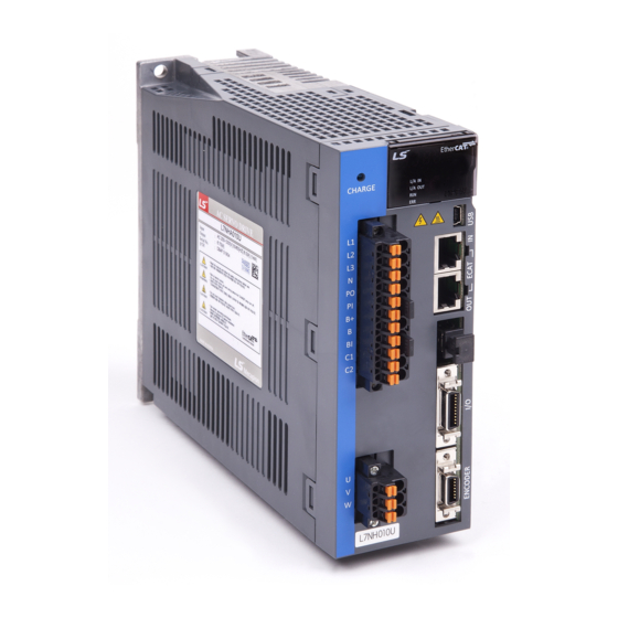
Page 16: Part Names
1. Product Configuration Part Names 1.3.1 Servo Drive Parts XDL-L7NH Drive (1KW) Connector for analog monitors Display It is a connector for checking the analog output It shows drive status, alarms, etc. signal. CHARGE lamp Node address setting switch This turns on when the main circuit power is on. - Page 17 1. Product Configuration XDL-L7NH Drive (2KW, 3.5KW) Connector for analog monitors Display It is a connector for checking the analog output It shows drive status, alarms, etc. signal. CHARGE lamp Node address setting switch This turns on when the main circuit This switch is to set the node address of the power is on.
- Page 18 1. Product Configuration XDL-L7NH Drive (5KW) Connector for analog monitors It is a connector for checking the analog output signal. Display It shows drive status, alarms, Node address setting switch etc. This switch is to set the node address of the drive.
- Page 19 1. Product Configuration XDL-L7NH Drive (7.5KW) Connector for analog monitors It is a connector for checking the analog output signal. Display It shows drive status, Node address setting switch alarms, etc. This switch is to set the node address of the drive.
- Page 20 1. Product Configuration XDL-L7NH Drive (15KW) Connector for analog monitors It is a connector for checking the analog Display output signal. It shows drive status, alarms, etc. Node address setting switch This switch is to set the node address of the drive.
-
Page 21: Servo Motor Parts
1. Product Configuration 1.3.2 Servo Motor Parts 80 Flange or below 130 Flange or higher... -
Page 22: System Configuration Example
1. Product Configuration System Configuration Example The figure below shows an example of system configuration using this drive. Power 전원 Three-phase AC380V 삼상 AC380V Upper device 상위 장치 R S T Molded case circuit breaker It is used to protect Oscilloscope 배선용... -
Page 23: Wiring And Connection
2. Wiring and Connection Wiring and Connection Installation of Servo Motor 2.1.1 Operating Environment Item Requirements Notes Ambient Consult with our technical support team to customize the product if 0 ∼ 40[℃] temperature temperatures in the installation environment are outside this range. Ambient 80% RH or lower Do not operate this device in an environment with steam. -
Page 24: The Load Device Connection
2. Wiring and Connection 2.1.4 The Load Device Connection For coupling connections: Ensure that the motor shaft and load shaft are aligned within the tolerance range. 0.03 ㎜ or below (peak to peak) Load shaft Motor shaft 0.03 ㎜ or below (peak to peak) ... -
Page 25: Installation Of Servo Drive
2. Wiring and Connection Installation of Servo Drive 2.2.1 Installation and Usage Environment Environmental Item Notes conditions Caution Ambient 0∼50[℃] Install a cooling fan on the control panel to maintain an temperature appropriate temperature. Caution Condensation or moisture may develop inside the drive during Ambient 90% RH or lower prolonged periods of inactivity and damage it. -
Page 26: Internal Block Diagram Of Drive
2. Wiring and Connection Internal Block Diagram of Drive 2.3.1 XDL-L7NH Drive Block Diagram (XDL L7NHB010U~ XDL-L7NHB035U) Note 2) Note 1) 주1) 주2) 010 : Thermistor Note 3) 주3) 써미스터 Diode IGBT 035 : Resistor Input 3-phase power 3상 전원 입력... -
Page 27: Xdl-L7Nh Drive Block Diagram (Xdl-L7Nhb050U~ Xdl-L7Nhb075U)
2. Wiring and Connection 2.3.2 XDL-L7NH Drive Block Diagram (XDL-L7NHB050U~ XDL-L7NHB075U) Note 5) Note 4) 주1) 주5) Note 6) 주6) 써미스터 Diode Resistor IGBT 3-phase power Regenerative Input 3상 전원 입력 회생저항 Current sensor Resistor 전류 센서 AC380~480V Thermistor 써미스터 Chage Lamp 써미스터... -
Page 28: Xdl-L7Nh Drive Block Diagram (Xdl-L7Nhb150U)
2. Wiring and Connection 2.3.3 XDL-L7NH Drive Block Diagram (XDL-L7NHB150U) External regenerative resistor Note 8) Note 7) Note 9) Resistor Regenerative 3-phase power Input Resistor Current sensor Thermistor Thermistor Regenerative Main Power Phase Internal PWM Signal SC U and V Current DC Voltage IGBT Temperature Control Power Phase... -
Page 29: Power Supply Wiring
2. Wiring and Connection Power Supply Wiring Ensure that the input power voltage is within the acceptable range. Caution Overvoltages can damage the drive. If commercial power is connected to U, V, W terminals of Drive, they may be damaged. Be sure to connect power to L1, L2, L3 terminals. -
Page 30: Power Supply Wiring Diagram
2. Wiring and Connection 2.4.1 Power Supply Wiring Diagram Power Supply Wiring Diagram(XDL-L7NHB010U~ XDL-L7NHB035U) AC 380~480[V] 서보드라이브 Servo Drive R S T 주1) Note 1) Main Main DC 리액터 DC reactor 엔코더 Encoder Alarm+ Alarm- Note 2) External 외부 주2) 회생저항... - Page 31 2. Wiring and Connection Power Supply Wiring Diagram(XDL-L7NHB050U~ XDL-L7NHB075U) Servo Drive Note 1) DC reactor Encoder Note 6) External regenerative resistor Power Supply Wiring Diagram(XDL-L7NHB150U) Servo Drive Note 1) DC reactor Encoder Note 7) External regenerative resistor...
- Page 32 2. Wiring and Connection Note 5) It takes approximately one to two seconds until alarm signal is output after you turn on the main power. Accordingly, push and hold the main power ON switch for at least two seconds. Note 6) Short-circuit B and BI terminals before use, because XDL-L7NHB050U(120[W], 27[Ω]), XDL-L7NHB075U(240[W], 27[Ω]) have internal regenerative resistance.
-
Page 33: Power Circuit Electrical Components
2. Wiring and Connection 2.4.2 Power Circuit Electrical Components XDL- XDL- XDL- XDL- XDL- XDL- Name L7NHB010U L7NHB020U L7NHB035U L7NHB050U L7NHB075U L7NHB150U 30A Frame 30A Frame 30A Frame 50A Frame 30A Frame MCCB (ABE33b/10) (ABE33b/30) (ABE33b/30) (ABE53b/50) (ABE33b/20) TB6- TB6- TB6- TB6- TB6-... - Page 34 2. Wiring and Connection XDL-L7NHB010U Wire strip 7~10[mm] Weidmuller SD 0.6x3.5x100 M4 : 1.2[N*m] XDL-L7NHB020U / XDL-L7NHB035U Wire strip 7~10[mm] Weldmuller M4 : 1.2[N*m] SD 0.6x3.5x100 2-12...
- Page 35 2. Wiring and Connection For information on wiring to BLZ 7.62HP Series connector, refer to the above procedures. Insert electric wire into insert hole with upper locking screw loosened, and use applicable flathead (-) driver for each model to fully tighten screw to 0.4-0.5 N·m. Otherwise, insufficient torque of locking screw may cause vibration-induced disconnection, system malfunction and contact-induced fire accident.
- Page 36 2. Wiring and Connection XDL-L7NHB050U NC : Internal Regenerative Resistor Screw for Fixing Lead Terminal Terminal signal Terminal screw: M4 Tightening torque: 1.2 N·m Terminal screw: M4 Tightening torque: 1.2 N·m Terminal screw: M4 Tightening torque: 1.2 N·m 1) Otherwise, insufficient torque of locking screw may cause vibration-induced disconnection, system malfunction and contact-induced fire accident.
- Page 37 2. Wiring and Connection XDL-L7NHB075U NC : Internal Regenerative Resistor Screw for Fixing Lead Terminal Terminal signal Terminal screw Tightening torque Terminal screw Tightening torque Terminal screw Tightening torque 1) Otherwise, insufficient torque of locking screw may cause vibration-induced disconnection, system malfunction and contact-induced fire accident.
- Page 38 2. Wiring and Connection XDL-L7NHB150U Terminal signal Terminal screw: M5 Tightening torque: 3.24 N·m Terminal screw: M4 Tightening torque: 1.2 N·m Terminal screw: M5 Tightening torque: 3.24 N·m 1) Otherwise, insufficient torque of locking screw may cause vibration-induced disconnection, system malfunction and contact-induced fire accident.
-
Page 39: Regenerative Resistor Options
2. Wiring and Connection 2.4.3 Regenerative Resistor Options Category Product Name Applicable Specifications Name Drive IRV300-82Ω Braking XDL- Resistance resistance L7NHB010U 82[Ω] (300W) IRV600- 140Ω XDL- L7NHB020U Braking Resistance 70Ω] / XDL- resistance L7NHB035U (600W *2P) (2P) - Making under review XDL- IRV600-75Ω... -
Page 40: Wiring For Input/Output Signals
2. Wiring and Connection Wiring for Input/Output Signals I/O Connector Specification : 10120-3000PE (3M) Analog Monitoring Connector Specification : DF-11-4DS-2C (HIROSE) 2.5.1 Names and Functions of Digital Input/Output Signals Names and Functions of Digital Input Signals (I/O Connector) name assignment Details... - Page 41 2. Wiring and Connection P control When the contact is on, it converts the PCON action mode from PI control to P control. Switch from When the contact is on, it switches the GAIN2 Gain 1 to 2 speed control gain 1 the gain 2 Forward When the contact is on, the forward torque limit...
-
Page 42: Names And Functions Of Analog Input/Output Signals
2. Wiring and Connection Outputs signal when the torque is ** TLMT Torque Limit limited. Outputs signal when the speed is ** VLMT Speed limit limited. Speed Outputs signal upon reaching the ** INSPD reached command speed. Servo ** WARN Outputs signal when a warning occurs. - Page 43 2. Wiring and Connection 2-21...
-
Page 44: Examples Of Connecting Input/Output Signals
2. Wiring and Connection 2.5.3 Examples of Connecting Input/Output Signals Examples of Connecting Digital Input Signals Caution 1. The input contact can be set to the contact A or the contact B, based on the characteristics of individual signal. 2. - Page 45 2. Wiring and Connection Servo Drive Internal Circuit Internal Circuit Note 1) For DO1~ DO4 output signals, the GND24 terminal is separated. Example of Connecting Analog Output Signals Caution 1. For more information on settings and scale adjustment of monitoring signals, refer to 5.2.3 Assignment of Analog output signals.
-
Page 46: Examples Of Connecting Input/Output Signals
2. Wiring and Connection 2.5.4 Examples of Connecting Input/Output Signals Digital Input Digital Output Analog Input Analog torque limit Safe function input Safety function output Analog Output Note 1) The input signals DI1 - DI8 and output signals DO1 - DO4 are the factory default signals. 2-24... -
Page 47: Wiring Of Encoder Signal (Encoder)
2. Wiring and Connection Wiring of Encoder Signal (ENCODER) ENCODER Connector Specification: 10114-3000VE (3M) 2.6.1 Quadrature Encoder Signaling Unit Wiring APCS-E AS Cable Servo Motor Servo Drive Encoder 2-25... -
Page 48: Serial Encoder Signaling Unit Wiring
2. Wiring and Connection APCS-E BS Cable Servo Motor Servo Drive Encoder 2.6.2 Serial Encoder Signaling Unit Wiring APCS-E CS Cable Servo Motor Servo Drive Encoder 2-26... - Page 49 2. Wiring and Connection APCS-E DS Cable Servo Motor Servo Drive Encoder APCS-E ES Cable Servo Motor Servo Drive Encoder 2-27...
-
Page 50: Multi-Turn Encoder Signaling Unit Wiring
2. Wiring and Connection 2.6.3 Multi-Turn Encoder Signaling Unit Wiring APCS-E CS1 Cable Servo Drive Servo Motor Encoder APCS-E DS1 Cable Servo Motor Servo Drive Encoder 2-28... -
Page 51: Tamagawa Encoder Signaling Unit Wiring
2. Wiring and Connection APCS-E ES1 Cable Servo Drive Servo Motor Encoder 2.6.4 Tamagawa Encoder Signaling Unit Wiring Servo Motor Servo Drive Encoder 2-29... -
Page 52: Endat 2.2 Encoder Signaling Unit Wiring
2. Wiring and Connection 2.6.5 EnDat 2.2 Encoder Signaling Unit Wiring Servo Motor Servo Drive Encoder 2-30... -
Page 53: Wiring For Safety Function Signals (Sto)
2. Wiring and Connection Wiring for Safety Function Signals (STO) 2069577-1(Tyco Electronics) 2.7.1 Names and Functions of Safety Function Signals name Function Number +12V For bypass wiring -12V STO1- DC 24 V GND STO1+ Blocks the current (torque) applied to the motor when the signal is off. STO2- DC 24 V GND STO2+... -
Page 54: Example Of Connecting Safety Function Signals
2. Wiring and Connection 2.7.2 Example of Connecting Safety Function Signals Caution 1. The rated voltage is DC 12 V to DC 24 V. 2. With the contacts of STO1 and STO2 off, the motor output current is blocked. 24 V power Driving signal Blocking Blocking... -
Page 55: Bypass Wiring Of Safety Function Signal
2. Wiring and Connection 2.7.3 Bypass Wiring of Safety Function Signal This drive provides the Mini I/O Bypass connector which has Bypass wiring to be used for the convenience of the user when the STO function is not used. To use the Bypass function, connect the Mini I/O Plug connector as follows. -
Page 56: Wiring For Ethercat Communication Signals
2. Wiring and Connection Wiring for EtherCAT Communication Signals 2.8.1 Names and Functions of EtherCAT Communication Signals EtherCAT IN and EtherCAT OUT Connector Signal Name Line color Number TX/RX0 + White/Orange TX/RX0 - Orange TX/RX1+ White/Green TX/RX2 - Blue TX/RX2 + White/Blue TX/RX1 -... -
Page 57: Example Of Drive Connection
2. Wiring and Connection 2.8.2 Example of Drive Connection The following figure shows the connection between a master and slave using EtherCAT communication. This is an example of a connection by topology of basic line type. For an environment with much noise, install ferrite core at both ends of the EtherCAT cable. 2-35... -
Page 59: Ethercat Communication
3. EtherCAT Communication EtherCAT Communication EtherCAT stands for Ethernet for Control Automation Technology. It is a communication method for masters and slaves which uses Real-Time Ethernet, developed by the German company BECKHOff and managed by the EtherCAT Technology Group (ETG). The basic concept of the EtherCAT communication is that, when a DataFrame sent from a master passes through a slave, the slave inputs the received data to the DataFrame as soon as it receives the data. -
Page 60: Ethercat State Machine
3. EtherCAT Communication 3.1.1 EtherCAT State Machine The EtherCAT drive has 5 states as above, and a state transition is done by an upper level controller (master). State Details A state for firmware update. Only mailbox communication using the FoE (File Boot access over EtherCAT) protocol is available. -
Page 61: Status Led
3. EtherCAT Communication Status LED The LEDs on the EtherCAT ports of this drive indicate the states of the EtherCAT communications and errors, as shown in the following figure. There are 3 green LEDs, which are L/A0, L/A1, and RUN, and 1 red ERR LED. - Page 62 3. EtherCAT Communication RUN LED The RUN LED indicates in which status the drive is in the EtherCAT State Machine. LED status Description The drive is in the Init state. The drive is in the Pre-Operational state. Blinking The drive is in the Safe-Operational state. Single Flash The drive is in the Operational state.
-
Page 63: Data Type
3. EtherCAT Communication Data Type The following table outlines the type and range of the data types used in this manual. Codes Description Range SINT Signed 8bit -128 ~127 USINT Unsigned 8bit 0 ~ 255 Signed 16bit -32768 ~ 32767 UINT Unsigned 16bit 0 ~ 65535... - Page 64 3. EtherCAT Communication SubIndex Setting values 0x02 (2 values assigned) Bit 31~16(Index) Bit 15~8(Sub index) Bit 7~0(Bit size) 0x6040 0x00 0x10 0x607A 0x00 0x20 This is an example to assign the Statusword, the Actual Position Value, and the Actual Velocity Value with the TxPDO (0x1A00).
- Page 65 3. EtherCAT Communication PDO Mapping The following tables list the PDO mappings set by default. These settings are defined in the EtherCAT Slave Information file (XML file). PDO Mapping: Target Modes of Touch Probe Target torque position Function Operation Touch probe 1 Position Operation...
-
Page 66: Synchronization Using The Dc (Distributed Clock)
3. EtherCAT Communication Synchronization Using the DC (Distributed Clock) The Distributed Clock (DC) synchronizes EtherCAT communication. The master and slave share a reference clock (system time) for synchronization, and the slave synchronizes its applications with the Sync0 event generated by the reference clock. The following synchronization modes exist in this drive. -
Page 67: Emergency Messages
3. EtherCAT Communication Emergency Messages Emergency messages are passed to the master via mailbox communication when a servo alarm occurs in the drive. Emergency messages may not be sent in the event of communication failure. Emergency messages consist of 8-byte data. Byte Emergency error Unique field for each manufacturer... -
Page 69: Cia402 Drive Profile
4. CiA402 Drive Profile CiA402 Drive Profile State machine Additional state State to be changed by the slave State which can be checked by the master The control power is on; the main power can be turned on. The control and main powers are on; torque cannot be applied to the motor. - Page 70 4. CiA402 Drive Profile State Machine Control Commands Switching states of the State Machine can be done through combinations of Controlword (0x6040) bits setting, as described in the table below: bits of the Controlword (0x6040) State Machine Command Bit 7 Bit 3 Bit 2 Bit 1...
-
Page 71: Operation Modes
4. CiA402 Drive Profile Switched on disabled Warning Remote Target reached Internal limit active Operation mode specific Torque limit active Drive specific Operation Modes This drive supports the following operation modes (0x6060): Profile Position Mode(PP) Homing Mode(HM) Profile Velocity Mode(PV) ... - Page 72 4. CiA402 Drive Profile Note 1) For the HM mode, the control mode is internally switched; thus, the function of speed feedforward and/or position command filter may be applied or not, depending on the operation condition. Related Objects Variable Index Name Accessibility...
-
Page 73: Position Control Modes
4. CiA402 Drive Profile Position Control Modes 4.3.1 Cyclic Synchronous Position Mode The Cyclic Synchronous Position (CSP) mode receives the target position (0x607A), renewed at every PDO update cycle, from the upper level controller, to control the position. In this mode, the controller is able to calculate the velocity offset (0x60B1) and the torque offset (0x60B2) corresponding the speed and torque feedforwards respectively, and pass them to the drive. - Page 74 4. CiA402 Drive Profile Related Objects Variable Index Name Accessibility Unit Index type assignment 0x6040 Controlword UINT 0x6041 Statusword UINT 0x607A Target Position DINT Software Position Limit Number of entries USINT 0x607D Min position limit DINT Max position limit DINT 0x6084 Profile Deceleration...
- Page 75 4. CiA402 Drive Profile Internal Block Diagram of CSP Mode...
-
Page 76: Profile Position Mode
4. CiA402 Drive Profile 4.3.2 Profile Position Mode Unlike the CSP mode receiving the target position, renewed at every PDO update cycle, from the upper level controller, in the Profile Position (PP) mode, the drive generates a position profile internally to operate up to the target position (0x607A) using the profile velocity (0x6081), acceleration (0x6083), and deceleration (0x6084). - Page 77 4. CiA402 Drive Profile Max position limit DINT 0x607F Maximum Profile Velocity UDINT UU/s 0x6081 Profile Velocity UDINT UU/s 0x6083 Profile Acceleration UDINT UU/s 0x6084 Profile Deceleration UDINT UU/s 0x6085 Quick Stop Deceleration UDINT UU/s 0x60B1 Velocity Offset DINT UU/s 0x60B2 Torque Offset 0.1%...
- Page 78 4. CiA402 Drive Profile Internal Block Diagram of PP Mode 4-10...
- Page 79 4. CiA402 Drive Profile You can use the following three position commands in Profile Position Mode: Single set point After reaching the target position, the drive sends a completion signal to the upper level controller and receives a new command. ...
- Page 80 4. CiA402 Drive Profile Change Immediately Driving Procedure (1) Specify the target position (0x607A). (2) Set the New setpoint bit to 1 and the Change set immediately bit to 1 to request the position operation. (3) You can begin a new position operation (New setpoint) regardless of the previous target position. The drive immediately moves to the new position.
-
Page 81: Velocity Control Mode
4. CiA402 Drive Profile Velocity Control Mode 4.4.1 Cyclic Synchronous Velocity Mode The Cyclic Synchronous Velocity (CSV) mode receives the target velocity (0x60FF), renewed at every PDO update cycle, from the upper level controller, to control the velocity. This mode allows the upper level controller to calculate the torque offset (0x60B2) corresponding the torque feedforward and pass it to the drive. - Page 82 4. CiA402 Drive Profile 0x606D Velocity Window UINT UU/s 0x606E Velocity Window Time UINT 0x6077 Torque Actual Value 0.1% 0x606C Velocity Actual Value DINT UU/s 0x6064 Position Actual Value DINT 0x6063 Position Actual Internal Value DINT pulse 4-14...
- Page 83 4. CiA402 Drive Profile Internal Block Diagram of CSV Mode 0x60B1 0x60FF Velocity Offset Target Velocity [UU/s] [UU/s] 0x606B Velocity Demand Value [UU/s] Processing Acc./Dec. Speed Command Gear Ratio Servo-Lock Acc. Time 0x2301 Function Motor 0x6091:01 Dec. Time 0x2302 Select 0x2311 0x6085...
-
Page 84: Profile Velocity Mode
4. CiA402 Drive Profile 4.4.2 Profile Velocity Mode Unlike the CSV mode receiving the target velocity, renewed at every PDO update cycle, from the upper level controller, in the Profile Velocity (PV) mode, the drive generates a velocity profile internally up to the target velocity (0x60FF) using the profile acceleration (0x6083) and deceleration (0x6084), in order to control its velocity. - Page 85 4. CiA402 Drive Profile Related Objects Variable Index Name Accessibility Unit Index type assignment 0x6040 Controlword UINT 0x6041 Statusword UINT 0x60FF Target Velocity DINT UU/s 0x607F Maximum Profile Velocity UDINT UU/s 0x6083 Profile Acceleration UDINT UU/s 0x6084 Profile Deceleration UDINT UU/s 0x6085...
- Page 86 4. CiA402 Drive Profile Internal Block Diagram of PV Mode 4-18...
-
Page 87: Torque Control Modes
4. CiA402 Drive Profile Torque Control Modes 4.5.1 Cyclic Synchronous Torque Mode The Cyclic Synchronous Torque (CST) mode receives the target torque (0x6071), renewed at every PDO update cycle, from the upper level controller, to control the torque. This mode allows the upper level controller to calculate the torque offset (0x60B2) corresponding the torque feedforward and pass it to the drive. - Page 88 4. CiA402 Drive Profile 0x6074 Torque Demand Value 0.1% 0x606C Velocity Actual Value DINT UU/s 0x606D Velocity Window UINT UU/s 0x606E Velocity Window Time UINT 0x6077 Torque Actual Value 0.1% 0x606C Velocity Actual Value DINT UU/s 0x6064 Position Actual Value DINT 0x6063 Position Actual Internal Value...
-
Page 89: Profile Torque Mode
4. CiA402 Drive Profile 4.5.2 Profile Torque Mode Unlike the CST mode receiving the target torque, renewed at every PDO update cycle, from the upper level controller, in the Profile Torque (PT) mode, the drive generates a torque profile internally up to the target torque (0x6071) by the torque slope (0x6087), in order to control its torque. - Page 90 4. CiA402 Drive Profile 0x606E Velocity Window Time UINT 0x6077 Torque Actual Value 0.1% 0x606C Velocity Actual Value DINT UU/s 0x6064 Position Actual Value DINT 0x6063 Position Actual Internal Value DINT pulse Internal Block Diagram of PT Mode 4-22...
-
Page 91: Homing
4. CiA402 Drive Profile Homing This drive provides its own homing function. The figure below represents the relationship between the input and output parameters for the homing mode. You can specify the speed, acceleration, offset, and homing method. Homing Method Homing Speeds Position demand internal value (0x60FC) Homing Acceleration... -
Page 92: Homing Method
4. CiA402 Drive Profile 4.6.1 Homing Method The drive supports the following homing methods (0x6098): Homing Method Details (0x6098) The drive returns to the home position with the negative limit switch (NOT) and the Index (Z) pulse while driving in the reverse direction. The drive returns to the home position with the positive limit switch (POT) and the Index (Z) pulse while driving in the forward direction. - Page 93 4. CiA402 Drive Profile Related Objects Variable Index Name Accessibility Unit Index type assignment 0x6040 Controlword UNIT 0x6041 Statusword UINT 0x607C Home Offset DINT 0x6098 Homing Method SINT Homing Speed Number of entries USINT 0x6099 Speed during search for switch UDINT UU/s Speed during search for zero...
- Page 94 4. CiA402 Drive Profile Homing Methods 1 and 2 Reverse (CW) Forward (CCW) For homing using the Homing Method 1, the velocity profile according to the sequence is as follows. See the details below: (A) The initial driving direction is reverse (CW), and the drive operates at the Switch Search Speed. (B) When the negative limit switch (NOT) is turned on, the drive switches its direction to the forward direction (CCW), decelerating to the Zero Search Speed.
- Page 95 4. CiA402 Drive Profile Methods 7, 8, 9, and 10 Reverse (CW) Forward (CCW) For homing using the Homing Method 7, the velocity profile according to the sequence is as follows. The sequence depends on the relationship between the load position and the Home switch at homing, which is categorized into three cases as below.
- Page 96 4. CiA402 Drive Profile (A) Since the Home signal is on, the drive will operate at the Switch Search Speed in the direction of the Positive Home Switch (CCW). It might not reach the Switch Search Speed depending on the start position of homing. (B) When the Home switch is turned off, the drive will decelerate to Zero Search Speed, and then continue to operate.
- Page 97 4. CiA402 Drive Profile Initial driving direction: Forward (CCW) Initial driving direction: Reverse (CCW) Methods 11, 12, 13, and 14 Reverse (CW) Forward (CW) For homing using the Homing Method 14, the velocity profile according to the sequence is as follows. The sequence depends on the relationship between the load position and the Home switch at homing, which is categorized into three cases as below.
- Page 98 4. CiA402 Drive Profile (1) At the start of homing, when the Home switch is OFF and the limit is not met during operation (A) The initial driving direction is reverse (CW), and the drive operates at the Switch Search Speed. (B) When the Negative Home switch is turned off, the drive will decelerate to Zero Search Speed, and then continue to operate.
- Page 99 4. CiA402 Drive Profile (3) At the start of homing, when the Home switch is OFF and the limit is met during operation (A) The initial driving direction is reverse (CW), and the drive operates at the Switch Search Speed. (B) When the negative limit switch (NOT) is turned on, the drive will decelerate down to stop, and then operate at the Switch Search Speed in the forward direction (CCW).
- Page 100 4. CiA402 Drive Profile Method 28 Reverse (CW) Forward (CCW) The initial driving direction is reverse (CW), and a point where the Positive Home Switch is turned on becomes the Home position. Method 33 and 34 Forward (CCW) Reverse (CW) The initial driving direction is reverse (CW) for the method 33, and forward (CCW) for the method 34.
- Page 101 4. CiA402 Drive Profile Method 35 Forward (CCW) Reverse (CW) The current position at startup of homing operation becomes the Home position. This method is used to change the current position to the origin depending on demand of the upper level controller. Homing methods -1, -2, -3 and -4 are supported by this drive besides the standard ones.
- Page 102 4. CiA402 Drive Profile Torque setting Time setting (A) The initial driving direction is reverse (CW), and the drive operates at the Switch Search Speed. (B) (B) When the drive hits the negative stopper, it will stand by according to the torque limit value (0x2409) and the time setting value (0x240A) at the time of homing using stopper before direction switch.
- Page 103 4. CiA402 Drive Profile Method -3 and -4 Reverse (CW) Forward (CCW) Homing method -3 and -4 only perform homing by using the Stopper. The velocity profile according to sequence is as follows. For more information, see the details below: Homing complete Torque setting Time setting...
- Page 104 4. CiA402 Drive Profile Methods -5, -6 ㅜ Homing Methods -5, -6 uses only Home switch to return to origin. The speed profile of each sequence is as follows. When limit switch is detected, Homing is stopped. Please see the explanations below for further details.
- Page 105 4. CiA402 Drive Profile (2) Cases where the home witch is off when homing begins, and the limit is met in the process Homing Method Speed Negative Limit switch ON Homing Error generated Time Switch search speed (0x6099:01) (A) The initial direction is reverse (CW). The motor operates at the switch search speed. When the negative limit switch is on, Homing Error is generated.
-
Page 106: Touch Probe Function
4. CiA402 Drive Profile Touch Probe Function Touch probe is a function to rapidly capture the position value of the encoder with external input (PROBE 1 and 2) signals or the Index (Z) pulse of the encoder. Example of Touch Probe Wafer mapper system of wafer transfer robot (WTR) In the case that wafers are piled up on a wafer stack, the presence of wafer can be determined by scanning the stack once using mapping sensor. - Page 107 4. CiA402 Drive Profile Related Objects Variable Index Name Accessibility Unit Index type assignment 0x60B8 Touch Probe Function UINT 0x60B9 Touch Probe Status UINT 0x60BA Touch Probe 1 Positive Edge Position Value DINT 0x60BB Touch Probe 1 Negative Edge Position Value DINT 0x60BC Touch Probe 2 Positive Edge Position Value...
- Page 108 4. CiA402 Drive Profile Continuous Trigger Mode (0x60B8.1=1, 0x60B8.9=1): In the continuous trigger mode, the bits 6, 7, 14, and 15 of the touch probe status (0x60B9) are toggled (0 1 or 1 0) every time the corresponding input/edge is input. ...
-
Page 109: Drive Application Functions
5. Drive Application Functions Drive Application Functions Drive Front Panel 아날로그 모니터 출력 커넥터 Analog monitor output connector L/A 0 L/A 1 노드 ID 설정 스위치 Node ID setting switch 서보 상태 표시 용 7-Segment 7-Segment for indicating servo status EtherCAT 통신... - Page 110 5. Drive Application Functions Servo ON Servo warning W10 occurred (code: 10) Digit4 indicates the current operation status and servo ready status. TGON signal indication (OFF: stop, ON: rotating) For position control: INPOS1 signal indication For speed control: INSPD signal indication For torque control: OFF For position control: Position command input in progress For speed control: Speed command input in progress...
- Page 111 5. Drive Application Functions An example of alarm status output Ex. 1) Limit signal input Ex. 2) Servo warning triggered Positive limit input W01 (main power phase loss) + W40 (low voltage warning) occurred INSPD, speed command input in progress, INPOS1, servo ready servo ready Position control mode, servo ON...
-
Page 112: Input/Output Signals Setting
5. Drive Application Functions Input/Output Signals Setting 5.2.1 Assignment of Digital Input Signals You can set the digital input signal function and input signal level of the I/O connector. You can arbitrarily assign up to 8 input functions out of 12 functions, as shown in the figure below, to the digital input signals 1-8 for use: Digital Input Assigned function... - Page 113 5. Drive Application Functions Setting Setting details Assignable input signals values Signal input level settings 0x00 Not assigned (0: contact A, 1: contact B) 0x01 14~8 Reserved 0x02 Assign input signal. 0x03 HOME 0x04 STOP Contact A: The default status is 0 (Low). Input 1 0x05 PCON (High) to actuate it (Active High).
-
Page 114: Assignment Of Digital Output Signals
5. Drive Application Functions 5.2.2 Assignment of Digital Output Signals You can set the digital output signal function and output signal level of the I/O connector. You can arbitrarily assign up to 4 output functions out of 11 functions, as shown in the figure below, to the digital output signals 1-4 for use: Servo Drive Digital Output... - Page 115 5. Drive Application Functions Setting details Setting values Assignable output signal Signal output level settings (0: contact A, 1: contact B) 0x00 Not assigned 14~8 Reserved 0x01 BRAKE Assign output signal 0x02 ALARM 0x03 0x04 ZSPD 0x05 INPOS1 0x06 TLMT 0x07 VLMT 0x08...
- Page 116 5. Drive Application Functions 5.2.3 Assignment of Analog Output Signals Providing 2 channels of Analog monitor to adjust drive gains or to monintor state parameter Retated objects Variable Index Name Accessibility Unit Index type assignment 0x2220 Analog Monitor Output Mode) UINT 0x2221 Analog Monitor Channel 1 Select...
- Page 117 5. Drive Application Functions Analog monitor output mode (0x2220) Analog monitor output range is -10~+10V. If setting value is 1, output value is positive value only. Analog monitor channel 1 setting (0x2221) Setting the parmeters to monitor through Analog monitor output channel 1 Th voltage is calculated as follow when analog monitor is output Channel 1 output voltage [V] = [Monitoring signal value(0x2221) –...
- Page 118 5. Drive Application Functions 5-10...
-
Page 119: Use Of User I/O
5. Drive Application Functions 5.2.4 Use of User I/O User I/O means that some of I/Os provided by the drive are used for individual purpose of the user, in addition to the purpose of controlling the drive itself. All contacts provided by the input/output connector(I/O) can be used as User I/O. - Page 120 5. Drive Application Functions Related Objects Variable Index Name Accessibility Unit Index type assignment 0x60FD Digital Inputs UDINT Description NOT (negative limit switch) POT (positive limit switch) HOME (origin sensor input) 3 to 15 Reserved DI #1(I/O pin 11), 0:Open, 1:Close DI #2(I/O pin 12), 0:Open, 1:Close DI #3(I/O pin 7), 0:Open, 1:Close DI #4(I/O pin 8), 0:Open, 1:Close...
- Page 121 5. Drive Application Functions How to Set User Output Servo Drive Digital Output Not assigned Upper Level Controller Not assigned Set the function of digital output port to be used as the user output to "Not assigned (setting value of 0)."...
- Page 122 5. Drive Application Functions Related Objects Variable Index Name Accessibility Unit Index type assignment Digital Outputs Number of entries USINT 0x60FE Physical outputs UDINT Bit mask UDINT They indicate the status of digital outputs. Description of physical outputs Description 0 to 15 Reserved...
-
Page 123: Electric Gear Setup
5. Drive Application Functions Electric Gear Setup 5.3.1 Electric Gear This function sets the electric gear when you want to drive a motor by so-called user unit, the minimum unit in which the user intends to give a command. When using the electric gear function of the drive, you cannot utilize the highest resolution of the encoder;... -
Page 124: Example Of Electric Gear Setup
5. Drive Application Functions Motor Revolutions =5000 Motor Revolutions =524288 Electric gear settings Shaft Revolutions = 10000 Shaft Revolutions = 10000 If the electric gear Can move through the same command of 12000 (12 mm= 12000 * 1 um), regardless is used of the encoder (motor) used. -
Page 125: Settings Related To Speed Control
5. Drive Application Functions Encoder specification 19-bit (524288 PPR) Amount of load 360/100/0.001=3600 movement/revolution Motor Revolutions : 524288 Electric gear settings Shaft Revolutions : 3600 Belt + Pulley System Apparatus specification Reduction gear ratio: 10/1, Pulley diameter: 100 mm User Unit 1um(0.001mm) Encoder specification... -
Page 126: Servo-Lock Function
5. Drive Application Functions Deceleration time = speed command / rated speed x speed command deceleration time (0x2302) As shown in the figure below, you can generate an S-curve shaped acceleration/deceleration profile for driving by setting the speed command S-curve time (0x2303) at a value of 1 or more. Make sure to verify the relationship between the acceleration/deceleration time and S-curve time. -
Page 127: Settings Related To Position Control
5. Drive Application Functions Speed Motor velocity TGON output range ZSPD output range Time In addition, if the difference between the command and the speed feedback (i.e., speed error) is not more than the INSPD output range (0x2406), an INSPD (speed match) signal will be output. ... - Page 128 5. Drive Application Functions Speed t velocity Target velocity Target velocity t velocity Command before filtering *63% Command after filtering Target velocity velocity *37% Time 0x2109 0x2109 Position command filter using position command filter time constant (0x2109) Speed Command before filtering Command before f Command after filtering Command after filte...
-
Page 129: Signals Related To Position Control
5. Drive Application Functions 5.5.2 Signals Related to Position Control As shown in the figure below, if the value of position error (i.e., the difference between the position command value input by the upper level controller and the position feedback value) is not more than the INPOS1 output range (0x2401), and is maintained for the INPOS1 output time (0x2402), the INPOS1 (position completed 1) signal will be output, provided that the position command is not renewed. -
Page 130: Settings Related To Torque Control
5. Drive Application Functions Settings Related to Torque Control 5.6.1 Speed Limit Function In the torque control mode, the torque command input from the upper level controller controls the torque, but does not control the speed; thus, the apparatus might be damaged due to exceedingly increased speed by an excessive torque command. -
Page 131: Positive/Negative Limit Settings
5. Drive Application Functions Positive/Negative Limit Settings This function is to safely operate the drive within the movable range of the apparatus using the positive/negative limit signals of the drive. Be sure to connect and set the limit switch for safe operation. For more information about the settings, refer to 5.2.1 Assignment of Digital Input Signals. -
Page 132: Setting The Brake Output Signal Function
5. Drive Application Functions Setting the Brake Output Signal Function If the motor stops due to servo OFF or servo alarm during rotation, you can set the speed (0x2407) and delay time (0x2408) for brake signal output, in order to configure the output timing. The brake signal will be output if the motor rotation speed goes below the set speed (0x2407) or the output delay time (0x2408) has elapsed after the servo OFF command. - Page 133 5. Drive Application Functions Servo OFF or Time when the PWM output alarm occurred is turned off Motor PWM OFF delay time (0x2411) Servo Load 부하 ON/OFF PWM output 중력방향 Gravity direction Brake signal (1) If Brake Signal Outputs First Before PWM Output Turns off You can output the brake signal first before the PWM output is turned off, preventing the drop along the vertical axis due to the gravity.
-
Page 134: Torque Limit Function
5. Drive Application Functions Torque Limit Function You can limit the drive output torque to protect the machine. It can be set by the torque limit function (0x2110). The setting unit of torque limit value is 0.1%. Description of Torque Limit Function Setting (0x2110) ... - Page 135 5. Drive Application Functions Forward torque limit External forward torque limit Torque input Internal and external torque limits Negative torque (set value 3) limit External negative torque limit Limits the torque using internal and external torque limit value according to the driving direction and the torque limit signal.
- Page 136 5. Drive Application Functions Maximum torque Forward torque limit External forward torque limit External negative torque limit Negative torque limit Related Objects Variable Index Name Accessibility Unit Index type assignment 0x2110 Torque Limit Function Select UINT 0x2111 External Positive Torque Limit Value UINT 0.1% 0x2112...
-
Page 137: Gain Switching Function
5. Drive Application Functions 5.10 Gain switching function 5.10.1 Gain group switching Use gain group 1 게인 그룹2 사용 게인 그룹1 사용 Use gain group 2 GAIN2 sensor input GAIN2 센서 입력 This function is to switch between the gain groups 1 and 2, as one of gain adjustment methods. You can reduce the time required for positioning through switching gains. - Page 138 5. Drive Application Functions Waiting time and switching time for gain switching is as follows: Gain group 1 Gain switching time 1 (0x211A) Gain group 2 Gain switching waiting time 1 (0x211C) Position loop gain 1 (0x2101) Position loop gain 2 (0x2105) Speed loop gain 1 (0x2102) Speed loop gain 2 (0x2106) Speed loop integral time constant 1 (x2103)
-
Page 139: P/Pi Control Switching
5. Drive Application Functions 5.10.2 P/PI Control Switching PI control uses both proportional (P) and integral (I) gains of the speed controller, while P control uses only proportional gain. The proportional gain determines the responsiveness of the entire controller, and the integral gain is used to eliminate an error in the steady state. - Page 140 5. Drive Application Functions Related Objects Variable Index Name Accessibility Unit Index type assignment 0x2114 P/PI Control Conversion Mode UINT 0x2115 P Control Switch Torque UINT 0.1% 0x2116 P Control Switch Speed UINT 0x2117 P Control Switch Acceleration UINT rpm/s 0x2118 P Control Switch Following Error...
-
Page 141: Dynamic Brake
5. Drive Application Functions 5.11 Dynamic brake What is Dynamic Brake? Dynamic brake electrically short-circuits the phase of the servo motor to stop it rapidly. Circuits related to the dynamic brake are integrated into the drive. The drive short-circuits only two phases or all of three phases depending on the model type. Drive Servo Motor You can set various stop modes, as shown below, in dynamic brake control mode settings [0x2012]:... -
Page 142: Regenerative Resistance Setting
5. Drive Application Functions Setting value: 2 Setting value: 3 Release the dynamic brake after free- Hold the dynamic brake after free-run run stop stop Related Objects Variable Index Name Accessibility Unit Index type assignment 0x2012 Dynamic Brake Control Mode UINT 0x2013 Emergency Stop Configuration... -
Page 143: Use Of Internal Regenerative Resistor
5. Drive Application Functions Related Objects Variable Index Name Accessibility Unit Index type assignment 0x2009 Regeneration Brake Resistor Configuration UINT 0x200A Regeneration Brake Resistor Derating Factor UINT 0x200B Regeneration Brake Resistor Value UINT Ω 0x200C Regeneration Brake Resistor Capacity UINT Watt 5.12.1 Use of Internal Regenerative Resistor... - Page 144 5. Drive Application Functions Set regenerative resistance (0x2009) - Configure to use the regenerative resistor integrated into the drive (0x2009 = 0). - Basically, the resistor is attached on the rear of the drive heat sink. - Initial value: 0 Check internal regenerative resistance value and capacity - Check the internal regenerative resistance value (0x200B).
-
Page 145: Use Of External Regenerative Resistor
5. Drive Application Functions 5.12.2 Use of External Regenerative Resistor When using the external regenerative resistor considering the driving condition, make sure to observe the order below for configuration: Wire the external regenerative resistor. - Remove the short circuit at B and BI terminals and connect the external regenerative resistance to B and B+ terminals (for 3.5KW or less) - Remove the internal regenerative resistance at B+ and B terminals and connect the external regenerative resistance to B+ and B terminals (for 5KW and 7.5KW) -
Page 146: Other Considerations
- Be sure to configure it when you have set the regenerative resistor (0x2009) to 1. LSIS provides the following regenerative resistors as options for the purpose of external regenerative resistor (see the specifications as well):... -
Page 147: Configuration Of Drive Node Address (Addr)
5. Drive Application Functions 5.13 Configuration of Drive Node Address (ADDR) Configure the drive node address. You can verify the set address in the node ID (0x2003). The value of the node setting switch is read just once when the power is turned on. Any set value modified subsequently will be in effect only when the power is turned on again. -
Page 149: Safety Functions
6. Safety Functions Safety Functions This servo drive has built-in safe torque off (STO) function to reduce the risk while using the machine by protecting people around the machine against dangerous operation of its movable parts. Especially, this function can be used to prevent dangerous operation of the machine's movable parts when you need to perform tasks such as maintenance in a danger zone. - Page 150 6. Safety Functions Timing diagram for STO operation Servo OFF Servo ON Servo ON/OFF STO state Normal state Motor supplied with power EDM output Dynamic brake relay (Operated by DB Control DB engaged DB disengaged Mode[0x2012] setting) PWM Off Delay Time[0x2011] setting + 3[ms](DB Hold time) Brake output Brake engaged...
- Page 151 6. Safety Functions Timing diagram for STO recovery Servo OFF Servo ON Servo ON/OFF After the servo is turned on, it operates according STO state to normal servo ON/OFF Normal state timing. Motor supplied with power EDM output Dynamic brake relay DB engaged Brake output Brake maintained...
-
Page 152: External Device Monitor (Edm)
6. Safety Functions External Device Monitor (EDM) Monitor output signal is to monitor the state of safety input signal with an external device. Connect it to the terminal for external device monitor of safety device such as safety controller or safety sensor. -
Page 153: Example Of Using Safety Function
6. Safety Functions Example of Using Safety Function Driving signal Blocking Blocking Safety unit EDM output How to Verify Safety Function In case that the servo drive was replaced prior to the device startup or during maintenance, make sure to check the details below: ... -
Page 154: Precautions For Using Safety Function
6. Safety Functions Precautions for Using Safety Function When using the STO function, be sure to carry out risk assessment for the device to check if the safety requirements of the system are met. There may be risks even if the STO function works. ... -
Page 155: Tuning
7. Tuning Tuning Current feedback Position Speed Torque Voltage command command command command Position Speed Torque Power Encoder control control control circuit Motor operation operation operation Position feedback The drive is set to the torque control, the speed control, or the position control mode for use, depending on the method to connect with the upper level controller. - Page 156 7. Tuning Related Objects Variable Index Name Accessibility Unit Index type assignment 0x250E System Rigidity for Gain Tuning UINT 0x2510 Off-line Gain Tuning Direction UINT 0x2511 Off-line Gain Tuning Distance UINT On-line Auto Gain Tuning Does not use the off-line auto gain tuning command generated by itself(XDL-L7NH Drive) and While operating under the command form host device, it sets parameters related gain automatically base on general rule and the rigidity set by user.
-
Page 157: Manual Gain Tuning
7. Tuning In the following cases, it may be inaccurate to estimate the inertia when online auto tuning. When a change of the load is too heavy When rigidity of load is too weak or too heavy backlash system. ... - Page 158 7. Tuning Position Controller Tuning (1) Proportional gain setting Monitor torque, positional error, and noise before any vibration occurs. (2) Feedforward setting Positional error monitoring Able to set the feedforward filter. Set the filter if you want to increase the feedforward value but noise occurs. You can set the feedforward value from 0% to 100%, which is the ratio of the position command value being entered currently and the deviation.
-
Page 159: Vibration Control
7. Tuning Vibration Control 7.4.1 Notch Filter Notch filter is a sort of band stop filter to eliminate specific frequency component. You can use a notch filter to eliminate the resonant frequency component of an apparatus, resulting in avoiding vibration while setting a higher gain. -
Page 160: Adaptive Filter
7. Tuning 7.4.2 Adaptive Filter Adaptive filter analyzes the real-time frequency of vibration frequency, generated from the load during the drive operation, through the speed feedback signal, and configures a notch filter automatically to reduce vibration. It can detect the vibration frequency through frequency analysis to automatically configure one or two notch filters. - Page 161 7. Tuning 7.4.3 Vibration Control (Damping) Filter Vibration control (damping) filter is to decrease vibration occurring in the load. Measuring vibration frequency occurring in the load throuth the external sensor, and using measured value as the object data for vibration control (damping) filter. XDL-L7NH has two vibration control (damping) filter in total.
-
Page 162: Analog Monitor
7. Tuning Setting Value Setting Details Not using Vibration control (damping) filter Applying Vibration control (damping) filter 1,2 Applying Vibration control (damping) filter 1,2 according to LVSF1, LVSF2 digital input. Analog Monitor Two channels of analog monitor outputs are provided to adjust drive gain or monitor internal status variables. - Page 163 7. Tuning Analog Monitor Channel 1 Setting 0x2221 UINT 0x2222 Analog Monitor Channel 2 Setting UINT Analog Monitor Channel 1 Offset 0x2223 DINT 0x2224 Analog Monitor Channel 2 Offset DINT 0x2225 Analog Monitor Channel 1 Scale UDINT 0x2226 Analog Monitor Channel 2 Scale UDINT ...
- Page 164 7. Tuning DC link voltage Accumulated Regeneration Overload Encoder single-turn data pulse Inertia ratio Full-Closed positional error Drive temperature 1 °C Drive temperature 2 °C Encoder temperature 1 °C The voltage is calculated as below during the analog monitor output: Channel 1 output voltage [V] = [Monitoring signal value (0x2221) –...
-
Page 165: Procedure Function
8. Procedure Function Procedure Function Procedure function is an auxiliary function provided by the drive as described below. It can be executed by procedure command code (0x2700) and procedure command factor (0x2701). It can be activated using servo setting tool. Procedure command Codes Details... -
Page 166: Programmed Jog Operation
8. Procedure Function Programmed Jog Operation Programmed jog operation is a function to verify the servo motor operation by the speed control at preset operation speed and time, without an upper level controller. Before starting the jog operation, make sure that: the main power is turned on;... -
Page 167: Deleting Alarm History
8. Procedure Function Related Objects Variable Index Name Accessibility Unit Index type assignment Programmed Jog Operation Speed 1 0x2304 (Program Jog Operation Speed 1) Programmed Jog Operation Speed 2 0x2305 (Program Jog Operation Speed 2) Programmed Jog Operation Speed 3 0x2306 (Program Jog Operation Speed 3) Programmed Jog Operation Speed 4... - Page 168 8. Procedure Function Related Objects Variable Index Name Accessibility Unit Index type assignment Servo Alarm History (Servo Alarm History) Alarm code 1 (Newest) STRING (Alarm code 1(Newest)) Alarm code 2 STRING (Alarm code 2) Alarm code 3 STRING (Alarm code 3) Alarm code 4 STRING (Alarm code 4)
-
Page 169: Auto Gain Tuning
8. Procedure Function Auto Gain Tuning For more information, refer to Section 7.1 Off-line Auto Gain Tuning. Index Pulse Search Index pulse search function is to find the Index (Z) pulse position of the encoder and stop. You can use this function to locate a position roughly since it searches for a position using the speed operation mode. -
Page 170: Absolute Encoder Reset
8. Procedure Function Absolute encoder reset This function resets the absolute encoder. You need to reset the absolute encoder if: you set up the apparatus for the first time; there occurs an alarm for low voltage of encoder; or you want to set multi-turn data of the absolute encoder to 0. -
Page 171: Phase Current Offset Tuning
8. Procedure Function Related Objects Variable Index Name Accessibility Unit Index type assignment Instantaneous Maximum Operation Overload 0x2604 0.1% (Instantaneous Maximum Operation Overload) Phase current offset tuning This function is to automatically tune the current offset of U/V/W phases. Depending on the environmental condition, you can tune the phase current offset for use. -
Page 172: Software Reset
8. Procedure Function Software reset This function is to reset the servo drive by means of software. Software reset means a restart of the drive program, resulting in an effect similar to recycling the power. You can use this function if: ... -
Page 173: Object Dictionary
9. Object Dictionary Object Dictionary Object is a data structure including parameters, state variables, run commands (procedures), and etc. within a drive. Object can be mainly divided into general object (from 0x1000) for EtherCAT communication, CiA402 object (from 0x6000) for CAN application over EtherCAT (CoE), and manufacturer specific object (from 0x2000) exclusively provided by this drive. - Page 174 9. Object Dictionary 0x1009 Hardware Version Variable Change Setting range Initial value Unit Accessibility Storage type attribute assignment STRING Represents the hardware version of the device. 0x100A Software Version Variable Change Setting range Initial value Unit Accessibility Storage type attribute assignment STRING Represents the software version of the device.
- Page 175 9. Object Dictionary Only CiA402 parameters (from 0x6000) are stored when "save" is written to SubIndex 3. Only drive-specific parameters (from 0x2000) are stored when "save" is written to SubIndex 4. 0x1011 Restore Default Parameters SubIndex 0 Number of entries Variable Change Setting range...
- Page 176 9. Object Dictionary UDINT 0x00007595 SubIndex 2 Product code Variable Change Setting range Initial value Unit Accessibility Storage type attribute assignment UDINT 0x00010001 SubIndex 3 Revision number Variable Change Setting range Initial value Unit Accessibility Storage type attribute assignment UDINT SubIndex 4 Serial number Variable...
- Page 177 9. Object Dictionary Variable Change Setting range Initial value Unit Accessibility Storage type attribute assignment UDINT 0 to 0xFFFFFFFF PREOP SubIndex 8 Mapping entry 8 Variable Change Setting range Initial value Unit Accessibility Storage type attribute assignment UDINT 0 to 0xFFFFFFFF PREOP SubIndex 9 Mapping entry 9...
- Page 178 9. Object Dictionary PDO Mapping : Configure the Process Data Objects (PDO) to perform real-time data transfer through the CANopen over EtherCAT protocol. This drive can freely map up to 10 objects of PDOs for transmission/reception, respectively. Use 0x1600 - 0x1603 to set the receiving PDO mapping, and 0x1A00 - 0x1A03 to set the transmitting PDO mapping.
- Page 179 9. Object Dictionary Variable Change Setting range Initial value Unit Accessibility Storage type attribute assignment UDINT 0 to 0xFFFFFFFF PREOP SubIndex 8 Mapping entry 8 Variable Change Setting range Initial value Unit Accessibility Storage type attribute assignment UDINT 0 to 0xFFFFFFFF PREOP SubIndex 9 Mapping entry 9...
- Page 180 9. Object Dictionary Variable Change Setting range Initial value Unit Accessibility Storage type attribute assignment UDINT 0 to 0xFFFFFFFF PREOP SubIndex 8 Mapping entry 8 Variable Change Setting range Initial value Unit Accessibility Storage type attribute assignment UDINT 0 to 0xFFFFFFFF PREOP SubIndex 9 Mapping entry 9...
- Page 181 9. Object Dictionary SubIndex 7 Mapping entry 7 Variable Change Setting range Initial value Unit Accessibility Storage type attribute assignment UDINT 0 to 0xFFFFFFFF PREOP SubIndex 8 Mapping entry 8 Variable Change Setting range Initial value Unit Accessibility Storage type attribute assignment UDINT...
- Page 182 9. Object Dictionary UDINT 0 to 0xFFFFFFFF 0x60610008 PREOP SubIndex 7 Mapping entry 7 Variable Change Setting range Initial value Unit Accessibility Storage type attribute assignment UDINT 0 to 0xFFFFFFFF 0x26010010 PREOP SubIndex 8 Mapping entry 8 Variable Change Setting range Initial value Unit Accessibility...
- Page 183 9. Object Dictionary type attribute assignment UDINT 0 to 0xFFFFFFFF 0x60FD0020 PREOP SubIndex 7 Mapping entry 7 Variable Change Setting range Initial value Unit Accessibility Storage type attribute assignment UDINT 0 to 0xFFFFFFFF PREOP SubIndex 8 Mapping entry 8 Variable Change Setting range Initial value...
- Page 184 9. Object Dictionary type attribute assignment UDINT 0 to 0xFFFFFFFF PREOP SubIndex 7 Mapping entry 7 Variable Change Setting range Initial value Unit Accessibility Storage type attribute assignment UDINT 0 to 0xFFFFFFFF PREOP SubIndex 8 Mapping entry 8 Variable Change Setting range Initial value Unit...
- Page 185 9. Object Dictionary Variable Change Setting range Initial value Unit Accessibility Storage type attribute assignment UDINT 0 to 0xFFFFFFFF PREOP SubIndex 7 Mapping entry 7 Variable Change Setting range Initial value Unit Accessibility Storage type attribute assignment UDINT 0 to 0xFFFFFFFF PREOP SubIndex 8 Mapping entry 8...
- Page 186 9. Object Dictionary 0x1C10 Sync Manager 0 PDO Assignment Variable Change Setting range Initial value Unit Accessibility Storage type attribute assignment USINT 0x1C11 Sync Manager 1 PDO Assignment Variable Change Setting range Initial value Unit Accessibility Storage type attribute assignment USINT 0x1C12 Sync Manager 2 PDO Assignment...
- Page 187 9. Object Dictionary Variable Change Setting range Initial value Unit Accessibility Storage type attribute assignment UDINT SubIndex 4 Sync modes supported Variable Change Setting range Initial value Unit Accessibility Storage type attribute assignment UINT 0x4007 SubIndex 5 Minimum cycle time Variable Change Setting range...
- Page 188 9. Object Dictionary Variable Change Setting range Initial value Unit Accessibility Storage type attribute assignment UDINT SubIndex 3 Shift time Variable Change Setting range Initial value Unit Accessibility Storage type attribute assignment UDINT SubIndex 4 Sync modes supported Variable Change Setting range Initial value Unit...
-
Page 189: Manufacturer Specific Objects
1 to 9999 recycling Set the motor ID. For the serial encoder provided by LSIS, it is automatically set. You can check the automatically set IDs. You can check the motor ID on the motor nameplate. Ex) The motor ID is 137 on the nameplate attached to the motor shown in the figure below:... - Page 190 (refer to the description of 0x2000). However, the serial encoder provided by LSIS is automatically recognized and configured regardless of these settings. Then, you can check the resolution of the encoder automatically recognized.
- Page 191 9. Object Dictionary feedback value increases. With a positive command, the motor rotates clockwise. Then, the position feedback value increases. (Reverse) (Forward) 0x2005 Absolute Encoder Configuration Variable Initial Change Setting range Unit Accessibility Storage type value assignment attribute Power UINT 0 to 1 recycling Set the usage of the absolute encoder.
- Page 192 9. Object Dictionary This specifies the checking interval for main power phase loss. This function detects instantaneous voltage drop or voltage sag, which may occur depending on the condition of external power input, to check the main power phase loss. Set this function properly according to the condition of external power input.
- Page 193 9. Object Dictionary 0x200A Regeneration Brake Resistor Derating Factor Variable Initial Change Setting range Unit Accessibility Storage type value assignment attribute UINT 0 to 200 Always This specifies the derating factor which checks for regenerative resistance overloads. When the derating is set to a value no more than 100[%], regeneration overload alarm (AL-23) will be triggered fast.
- Page 194 9. Object Dictionary 0x200F Overload Check Base Variable Initial Change Setting range Unit Accessibility Storage type value assignment attribute Always UINT 10 to 120 This indicates the load factor at which operation overload starts to be accumulated. When this is set to a value no more than 100, operation overload will start to be accumulated earlier at the set load factor to result in early trigger of operation overload alarm (AL-21).
- Page 195 9. Object Dictionary Time Time Hold after a DB stop Hold after a free run stop Time Time Release after a free run stop Release after a DB stop 0x2013 Emergency Stop Configuration Variable Initial Change Setting range Unit Accessibility Storage type value...
- Page 196 9. Object Dictionary Software Position Limit Operation overload Abnormal combination of drive and motor, abnormal I/O setting Low voltage Emergency signal input 8~14 STO not connected Statusword fault bit set 0x2015 U Phase Current Offset Variable Initial Change Setting range Unit Accessibility Storage...
- Page 197 9. Object Dictionary 0x2018 Magnetic Pole Pitch Variable Setting Initial Change Unit Accessibility Storage type range value assignment attribute Power UINT 1 to 65535 2400 .01mm recycling This specifies the pitch between the magnetic poles of the linear motor. The pole pitch refers to the distance between the north poles or between the south poles of magnet, corresponding to 360˚...
- Page 198 9. Object Dictionary 0x201D Grating Period of Sinusoidal Encoder Variable Initial Change Setting range Unit Accessibility Storage attribute type value assignment Power UINT 1 to 65535 recycling Set grid of sinusoidal encoder 0x201E Homing Done Behaviour Variable Initial Change Setting range Unit Accessibility Storage...
- Page 199 9. Object Dictionary 0x2020 Motor Hall Phase Config Variable Initial Change Setting range Unit Accessibility Storage attribute type value assignment Power UINT 0 to 1 recycling Checking the motor wiring and hall sensor wiring in case of 3rd party motor and Setting the sequence of hall sensor UVW, polarity of hall sensor signal and motor rotation direction.
- Page 200 9. Object Dictionary Gain Adjustment(0x2100~ ) 0x2100 Inertia Ratio Variable Initial Change Setting range Unit Accessibility Storage type value assignment attribute UINT 0 to 3000 Always This specifies the ratio of the load inertia to the motor's rotor inertia in %. Inertia ratio = Load inertia / Motor's rotor inertia x 100 The inertia/load ratio is an important control parameter for the operation of the servo.
- Page 201 9. Object Dictionary 0x2105 Position Loop Gain 2 Variable Initial Change Setting range Unit Accessibility Storage type value assignment attribute UINT 1 to 500 Always This specifies the position loop gain used as gain group 2 for gain switching. For more information, refer to the description of the Position Loop Gain 1 (0x2101).
- Page 202 9. Object Dictionary 0x210A Position Command Average Filter Time Constant Variable Initial Change Setting range Unit Accessibility Storage type value assignment attribute UINT 0 to 10000 0.1ms Always This applies a moving average filter for position command to smoothen the position command. The value of Position Command Filter Time Constant (0x2109) is first applied.
- Page 203 9. Object Dictionary 0x210F Torque Feed-forward Filter Time Constant Variable Initial Change Setting range Unit Accessibility Storage type value assignment attribute UINT 0 to 1000 Always This applies low pass filter to the compensated amount added to the torque command by the torque feed-forward gain.
- Page 204 9. Object Dictionary 0x2112 External Negative Torque Limit Value Variable Initial Change Setting range Unit Accessibility Storage type value assignment attribute UINT 0 to 5000 3000 0.1% Always This specifies the external negative torque limit value according to the torque limit function setting (0x2110).
- Page 205 9. Object Dictionary 0x2116 P Control Switch Speed Variable Initial Change Setting range Unit Accessibility Storage type value assignment attribute UINT 0 to 6000 Always Refer to the description of the P/PI control switching mode (0X2114). 0x2117 P Control Switch Acceleration Variable Initial Change...
- Page 206 9. Object Dictionary - 1: Use gain group 2 Reserved Reserved Reserved Gain is switched according to the ZSPD output status. - 0: Use gain group 1 - 1: Use gain group 2 Gain is switched according to the INPOS1 output status. - 0: Use gain group 1 - 1: Use gain group 2 0x211A...
- Page 207 9. Object Dictionary 0x211E Dead Band for Position Control Variable Initial Change Setting range Unit Accessibility Storage type value assignment attribute UINT 0 to 1000 Always The position controller output is 0 if positional error for position control is below the setting. 0x211F Drive Control Input 1 Variable...
- Page 208 9. Object Dictionary 0x2121 Drive Status Output 1 Variable Initial Change Setting range Unit Accessibility Storage type value assignment attribute UINT 0 to FFFF Always You can assign the state of the drive output signal to the I/O output signal, in order to verify the applicable bit of this output value, in addition to actual output.
- Page 209 9. Object Dictionary I/O Configuration (from 0x2200) 0x2200 Digital Input Signal 1 Selection Variable Initial Change Setting range Unit Accessibility Storage type value assignment attribute UINT 0 to 0xFFFF 0x0001 Always This specifies the functions of digital input signal 1 of the I/O and the input signal level. Setting example) If the setting value is 0x006: Setting Assigned signal...
- Page 210 9. Object Dictionary 0x2203 Digital Input Signal 4 Selection Variable Initial Change Setting range Unit Accessibility Storage type value assignment attribute Power UINT 0 to 0xFFFF 0x0004 recycling This specifies the functions of digital input signal 4 of the I/O and the input signal level. For more information, refer to the description of 0x2200.
- Page 211 9. Object Dictionary 0x2210 Digital Output Signal 1 Selection Variable Initial Change Setting range Unit Accessibility Storage type value assignment attribute Power UINT 0 to 0xFFFF 0x8001 recycling Assign the functions of digital output signal 1 of I/O and set the output signal level. Setting example) If the setting value is 0x8001: Setting Assigned signal...
- Page 212 9. Object Dictionary Assign the functions of digital output signal 4 of I/O and set the output signal level. For more information, refer to the description of 0x2210. 0x221C Analog Torque Limit Scale Variable Initial Change Setting range Unit Accessibility Storage type value...
- Page 213 9. Object Dictionary Torque feedback Torque command Positional Error pulse Accumulated Operation Overload DC link voltage Accumulated Regeneration Overload Encoder single-turn data pulse Inertia Ratio Full-Closed positional error Drive Temperature 1 °C Drive Temperature 2 °C Encoder temperature 1 °C 0x2222 Analog Monitor Channel 2 Select Variable...
- Page 214 9. Object Dictionary 0x2225 Analog Monitor Channel 1 Scale Variable Initial Change Setting range Unit Accessibility Storage type value assignment attribute 0 to UDINT Always 0x40000000 This specifies the scaling of the variable to be output per 1 V when outputting the monitoring variable configured as the analog output channel 1.
- Page 215 9. Object Dictionary Velocity Control(0x2300~ ) 0x2300 Jog Operation Speed Variable Initial Change Setting range Unit Accessibility Storage type value assignment attribute -6000 to 6000 rpm, Always This specifies the jog operation speed. 0x2301 Speed Command Acceleration Time Variable Initial Change Setting range...
- Page 216 9. Object Dictionary 0x2305 Program Jog Operation Speed 2 Variable Initial Change Setting range Unit Accessibility Storage type value assignment attribute -6000 to 6000 Always Refer to the description of Programmed Jog Operation Speed 1 (0x2304). 0x2306 Program Jog Operation Speed 3 Variable Initial Change...
- Page 217 9. Object Dictionary 0x230A Program Jog Operation Time 3 Variable Initial Change Setting range Unit Accessibility Storage type value assignment attribute UINT 0 to 10000 Always Refer to the description of Programmed Jog Operation Speed 1 (0x2304). 0x230B Program Jog Operation Time 4 Variable Initial Change...
- Page 218 9. Object Dictionary 0x230F Over Speed Detection Level Variable Initial Change Setting range Unit Accessibility Storage type value assignment attribute UINT 0 to 10000 6000 Always This specifies the level to detect overspeed alarms (AL-50). If the setting is larger than the maximum motor speed, the detection level will be set by the maximum motor speed.
- Page 219 9. Object Dictionary Miscellaneous Setting(0x2400~ ) 0x2400 Software Position Limit Function Select Variable Initial Change Setting range Unit Accessibility Storage type value assignment attribute UINT 0 to 3 Always This specifies the software position limit function for position control. When using the position limit function, the upper and the lower limit values will be limited to the values configured in (0x670D:02) and (0x670D:01), respectively.
- Page 220 9. Object Dictionary 0x2404 ZSPD Output Range Variable Initial Change Setting range Unit Accessibility Storage type value assignment attribute UINT 0 to 6000 Always When the current speed is less than the setting value, the ZSPD signal is output. 0x2405 TGON Output Range Variable Initial...
- Page 221 9. Object Dictionary 0x2409 Torque Limit for Homing Using Stopper Variable Initial Change Setting range Unit Accessibility Storage type value assignment attribute UINT 0 to 2000 0.1% Always This specifies the torque limit value for homing using a stopper. With too large of a value configured, the machine may collide with the stopper.
- Page 222 9. Object Dictionary 0x240D User Drive Name Variable Initial Change Setting range Unit Accessibility Storage type value assignment attribute STRING ‘Drive’ Always The user can customize the drive name. Up to 16 characters can be used to define the name. 0x240E Individual Parameter Storage Variable...
- Page 223 9. Object Dictionary Enhanced Control(0x2500~ ) 0x2500 Adaptive Filter Function Select Variable Initial Change Setting range Unit Accessibility Storage type value assignment attribute UINT 0 to 5 Always This specifies the adaptive filter function. Setting values Setting details Adaptive filter is not used. Only one adaptive filter is used.
- Page 224 9. Object Dictionary 0x2504 Notch Filter 2 Frequency Variable Initial Change Setting range Unit Accessibility Storage type value assignment attribute UINT 50 to 5000 5000 Servo off 0x2505 Notch Filter 2 Width Variable Initial Change Setting range Unit Accessibility Storage type value assignment...
- Page 225 9. Object Dictionary 0x250B Notch Filter 4 Width Variable Initial Change Setting range Unit Accessibility Storage type value assignment attribute UINT 1 to 100 Servo off 0x250C Notch Filter 4 Depth Variable Initial Change Setting range Unit Accessibility Storage type value assignment attribute...
- Page 226 9. Object Dictionary 0x2510 Off-line Gain Tuning Direction Variable Initial Change Setting range Unit Accessibility Storage type value assignment attribute UINT 0 to 1 Servo off This specifies the movement direction when performing the Off-line Gain Tuning. Set the function properly according to the condition of the apparatus section.
- Page 227 9. Object Dictionary 0x2515 Vibration Suppression Filter Configuration Variable Initial Change Setting range Unit Accessibility Storage type value assignment attribute UINT 0 to 5 Servo off (Description will be added later) 0x2516 Vibration Suppression Filter 1 Frequency Variable Initial Change Setting range Unit Accessibility...
- Page 228 9. Object Dictionary Monitoring (from 0x2600) 0x2600 Feedback Speed Variable Initial Change Setting range Unit Accessibility Storage type value assignment attribute This represents the current rotation speed of the motor. 0x2601 Command Speed Variable Initial Change Setting range Unit Accessibility Storage type...
- Page 229 9. Object Dictionary 0x2605 DC-Link Voltage Variable Initial Change Setting range Unit Accessibility Storage type value assignment attribute UINT Volt This represents the DC link voltage by the main power input. 0x2606 Accumulated Regeneration Overload Variable Initial Change Setting range Unit Accessibility Storage...
- Page 230 This represents the temperature measured by the temperature sensor integrated into serial encoder provided by LSIS (if the setting values of the encoder type (0x2001) are 3, 4, 5, and 6). If the measured temperature is higher than 90℃, the encoder overheat alarm (AL-26) will be generated.
- Page 231 9. Object Dictionary 0x260F Motor Maximum Speed Variable Initial Change Setting range Unit Accessibility Storage type value assignment attribute UINT This represents the maximum speed of the driving motor. 0x2610 Drive Rated Current Variable Initial Change Setting range Unit Accessibility Storage type value...
- Page 232 9. Object Dictionary This represents the bootloader version of the drive. 0x2614 Warning Code Variable Initial Change Setting range Unit Accessibility Storage type value assignment attribute UINT This represents a warning code which has occurred in the drive. 0x2615 Analog Input Channel 1 Value Variable Initial Change...
- Page 233 9. Object Dictionary Procedure and Alarm history(0x2700~ ) 0x2700 Procedure Command Code Variable Initial Change Setting range Unit Accessibility Storage type value assignment attribute UINT 0 to 0xFFFF You can run various procedures with the following procedure command codes and command arguments.
- Page 234 9. Object Dictionary 0x2702 Servo Alarm History SubIndex 0 Number of entries Variable Initial Change Setting range Unit Accessibility Storage type value assignment attribute STRING SubIndex 1 Alarm code 1 (Newest) Variable Initial Change Setting range Unit Accessibility Storage type value assignment attribute...
- Page 235 9. Object Dictionary SubIndex 9 Alarm code 9 Variable Initial Change Setting range Unit Accessibility Storage type value assignment attribute STRING SubIndex 10 Alarm code 10 Variable Initial Change Setting range Unit Accessibility Storage type value assignment attribute STRING SubIndex 11 Alarm code 11 Variable Initial...
- Page 236 9. Object Dictionary Third Party Motor Support(0x2800~ ) The following motor parameters are provided to drive a motor manufactured by a third party in addition to our motor. To drive a third party's motor through our drive, you have to enter correct parameters. In this case, however, our company neither has performed any test for the combination of our drive and the third party motor, nor gives any warranty for the motor characteristic.
- Page 237 9. Object Dictionary 0x2804 [Third Party Motor] Rated Speed Variable Initial Change Setting range Unit Accessibility Storage type value assignment attribute Power UINT 1 to 60000 3000 recycling This specifies the rated speed of the motor. For a linear motor, the unit is mm/s. 0x2805 [Third Party Motor] Maximum Speed Variable...
- Page 238 9. Object Dictionary 0x2809 [Third Party Motor] Phase Inductance Variable Initial Change Setting range Unit Accessibility Storage attribute type value assignment Power FP32 0 to 1000 3.66 recycling This specifies the phase inductance (= inductance between lines ÷ 2) of the motor. 0x280A [Third Party Motor] TN Curve Data 1 Variable...
- Page 239 9. Object Dictionary 0x280C [Third Party Motor] Hall Offset Variable Initial Change Setting range Unit Accessibility Storage type value assignment attribute Power UINT 0 to 360 recycling The offset of the hall sensor attached for initial angle of a 3rd party motor may vary depending on manufacturer.
-
Page 240: Cia402 Objects
9. Object Dictionary CiA402 Objects 0x603F Error Code Variable Initial Change Setting range Unit Accessibility Storage type value assignment attribute UINT The alarm code which has last occurred in Servo Drive is displayed. 0x6040 Controlword Variable Initial Change Setting range Unit Accessibility Storage... - Page 241 9. Object Dictionary Enable operation <Description on Bits 4 to 9> • Bits 4, 5 and 9: For PP mode operation Bit 9 Bit 5 Bit 4 Details It proceeds to the next position when the operation at the current 0 →...
- Page 242 9. Object Dictionary • Bits 4, 5, 6, 8 and 9: For IP mode operation Function Value Details Interpolation disabled Use of Interpolation Interpolation enabled – – Halt Runs the bit 4 command. Halts the operation according to the Halt Option code (0x605D). –...
- Page 243 9. Object Dictionary Operation mode Refer to the sections concerning bits 10, 12 and 13. specific Internal limit active Refer to the section concerning bit 11. Operation mode 12 to 13 Refer to the sections concerning bits 10, 12 and 13. specific Torque limit active 0: no torque limit active 1: torque limit active...
- Page 244 9. Object Dictionary No positional error Following error Positional error • Bits 10, 12 and 13: For homing mode operation Bit 13 Bit 12 Bit 10 Details Homing Homing Target error attained reached Homing in progress Homing stopped or not started Performed homing operation, but the not reach the target Homing completed Homing error;...
- Page 245 9. Object Dictionary • Bits 10, 12 and 13: For PV mode operation State Value Details Halt (0x6040.8) = 0: Unable to reach the target position Halt (0x6040.8) = 1: deceleration Target reached Halt (0x6040.8) = 0: Reached the target position Halt (0x6040.8) = 1: Speed is 0 Not in a zero speed state Speed...
- Page 246 9. Object Dictionary Setting values Description Not used Decelerates to a stop; enters the Switch On Disabled state; enters the Ready state 0x605C Disable Operation Option Code Variable Initial Change Setting range Unit Accessibility Storage type value assignment attribute 0 to 1 Always This specifies the Disable Operation state (Operation Enabled state ...
- Page 247 9. Object Dictionary 0x6060 Modes of Operation Variable Setting Initial Change Unit Accessibility Storage type range value assignment attribute SINT 0 to 10 Always This sets the servo drive operation mode. The master sets the operation mode when the power is turned on.
- Page 248 9. Object Dictionary DINT pulse This displays the actual internal position value in encoder pulses. 0x6064 Position Actual Value Variable Setting Initial Change Stora Unit Accessibility type range value assignment attribute DINT This displays the actual position value in user-defined position units (UU). 0x6065 Following Error Window Variable...
- Page 249 9. Object Dictionary 0x606B Velocity Demand Value Variable Setting Change Stora Initial value Unit Accessibility type range assignment attribute DINT UU/s This displays the output speed of the position controller or the command speed input to the speed controller. 0x606C Velocity Actual Value Variable Setting...
- Page 250 9. Object Dictionary 0x6072 Maximum Torque Variable Setting Initial Change Stora Unit Accessibility type range value assignment attribute UINT 0 to 5000 3000 0.1% Always This sets the maximum torque that the motor can output in 0.1% increments of the rated torque. 0x6074 Torque Demand Value Variable...
- Page 251 9. Object Dictionary • Absolute Encoder If the absolute encoder is connected, then the home offset value is added to the absolute position (the actual position value). 0x607D Software Position Limit SubIndex 0 Number of entries Variable Accessibil Change Setting range Initial value Unit Storage...
- Page 252 9. Object Dictionary 0x6083 Profile Acceleration Variable Initial Accessibilit Change Stora Setting range Unit type value assignment attribute 0 to UDINT 200000 UU/s Always 0x7FFFFFFF This specifies the profile acceleration for the PP mode operation. 0x6084 Profile Deceleration Variable Initial Accessibilit Change Stora...
- Page 253 9. Object Dictionary recycling SubIndex 2 Shaft revolutions Variable Accessibil Change Setting range Initial value Unit Storage type assignment attribute Power DINT 0 to 0x40000000 recycling For more information, refer to Section 5.3 Electric Gear Setup. 0x6098 Homing Method Variable Initial Change Stora...
- Page 254 9. Object Dictionary 0x6099 Homing Speeds SubIndex 0 Number of entries(Number of entries) Variable Accessibil Change Setting range Initial value Unit Storage type assignment attribute USINT SubIndex 1 Switch search speed(Speed during search for switch) Variable Accessibil Change Setting range Initial value Unit Storage...
- Page 255 9. Object Dictionary 0x60B2 Torque Offset Variable Initial Accessibilit Change Stora Setting range Unit type value assignment attribute -5000 to 5000 0.1% Always In the CSP and CSV modes, this corresponds to the torque feedforward value. In the CST mode, this specifies the offset value added to the torque command value. 0x60B8 Touch Probe Function Variable...
- Page 256 9. Object Dictionary Captures the falling edge position value of the touch probe 2. 14 to 15 – Reserved 0x60B9 Touch Probe Status Variable Initial Change Stora Setting range Unit Accessibility type value assignment attribute UINT This displays the status of the touch probe. Value Description Does not use the touch probe 1.
- Page 257 9. Object Dictionary 0x60BA Touch Probe 1 Positive Edge Position Value Variable Initial Change Stora Setting range Unit Accessibility type value assignment attribute DINT This represents the rising edge position value of the touch probe 1. 0x60BB Touch Probe 1 Negative Edge Position Value Variable Initial Change...
- Page 258 9. Object Dictionary 0x60F4 Following Error Actual Value Variable Initial Change Stora Setting range Unit Accessibility type value assignment attribute DINT This displays the actual position error during position control. 0x60FC Position Demand Internal Value Variable Initial Change Stora Setting range Unit Accessibility type...
- Page 259 9. Object Dictionary 0x60FE Digital Outputs SubIndex 0 Number of entries Variable Accessibil Change Setting range Initial value Unit Storage type assignment attribute USINT SubIndex 1 Physical outputs Variable Accessibil Change Setting range Initial value Unit Storage type assignment attribute UDINT 0 to 0xFFFFFFFF Always...
- Page 260 9. Object Dictionary 0 to 15 Reserved Forced output setting (0: Disable, 1: Enable) of DO #1 (I/O pins 3 and 4) Forced output setting (0: Disable, 1: Enable) of DO #2 (I/O pins 23 and 24) Forced output setting (0: Disable, 1: Enable) of DO #3 (I/O pins 25 and 26) Forced output setting (0: Disable, 1: Enable) of DO #4 (I/O pins 1 and 2)
-
Page 261: Product Specifications
10. Product Specifications Product Specifications 10.1 Servo Motor 10.1.1 Product Characteristcs SEP09A SEP15A SEP22A SEP30A SEP06D SEP11D Servo Motor Type (APM- ) L7□B010□ L7□B020□ L7□B035□ L7□B010□ Applicable Drive (L7 B ) Rated Output [kW] 2.86 4.77 9.55 2.86 5.25 [Nm] Rated torque [kgfcm] 29.23... - Page 262 10. Product Specifications Rotational speed-Torque Characteristics Servo Motor Type (APM- ) SEP16D SEP22D SEP05G SEP09G SEP13G SEP17G L7□B020□ L7□B010□ L7□B020□ Applicable Drive (L7 B ) 10-2...
- Page 263 10. Product Specifications Rated Output [kW] 0.45 0.85 7.64 10.5 2.86 5.41 8.28 10.82 [Nm] Rated torque [kgfcm] 77.95 107.19 29.23 55.22 84.45 110.43 Maximum [Nm] 22.92 31.51 8.59 16.23 24.83 32.47 instantaneous 233.86 321.56 87.70 165.65 253.35 331.30 [kgfcm] torque Rated Current 4.79...
- Page 264 10. Product Specifications Rated Output [kW] 2.86 5.73 8.59 11.46 9.55 15.92 [Nm] Rated torque [kgfcm] 29.23 58.47 87.70 116.93 97.44 162.40 Maximum [Nm] 8.59 17.19 25.78 34.38 28.65 39.79 instantaneous 87.70 175.40 263.09 350.79 292.33 406.01 [kgfcm] torque Rated Current 2.52 2.42 3.62...
- Page 265 10. Product Specifications Applicable Drive (L7 B ) L7□B020□ L7□B035□ L7□B050□ L7□B075□ L7□B020□ L7□B050□ Rated Output [kW] 10.50 16.71 26.26 35.81 11.46 18.46 [Nm] Rated torque [kgfcm] 107.19 170.52 267.96 365.41 116.93 188.39 Maximum 31.51 50.13 65.65 89.52 34.38 55.39 [Nm] instantaneous torque...
- Page 266 10. Product Specifications Applicable Drive (L7 B ) L7□B050□ L7□B075□ L7□B150□ L7□B020□ L7□B050□ Rated Output [kW] 28.01 38.20 47.75 11.46 19.10 28.65 [Nm] Rated torque [kgfcm] 285.83 389.77 487.21 116.93 194.88 292.33 Maximum 70.03 95.49 119.37 34.38 57.30 71.62 [Nm] instantaneous torque [kgfcm]...
- Page 267 10. Product Specifications Applicable Drive (L7 B ) L7□B050□ L7□B020□ L7□B035□ L7□B050□ L7□B075□ L7□B150□ Rated Output [kW] 11.0 42.02 10.50 16.71 26.26 35.81 52.52 [Nm] Rated torque [kgfcm] 428.74 107.19 170.52 267.96 365.41 535.93 Maximum 105.04 31.51 50.13 78.78 89.52 131.30 [Nm] instantaneous...
- Page 268 10. Product Specifications Applicable Drive (L7 B ) L7□B020□ L7□B050□ L7□B050□ L7□B075□ L7□B150□ Rated Output [kW] 11.0 11.46 18.46 28.01 38.20 54.11 70.03 [Nm] Rated torque [kgfcm] 116.93 188.39 285.83 389.77 552.17 714.57 Maximum 34.38 55.39 70.03 95.49 135.28 175.07 [Nm] instantaneous torque...
- Page 269 10. Product Specifications Applicable Drive (L7 B ) L7□B150□ L7□B020□ L7□B050□ L7□B150□ Rated Output [kW] 15.0 95.49 11.46 19.10 28.65 42.02 57.30 [Nm] Rated torque [kgfcm] 974.42 116.93 194.88 292.33 428.74 584.65 Maximum 238.73 34.38 57.30 85.94 105.04 143.24 [Nm] instantaneous torque [kgfcm]...
- Page 270 10. Product Specifications Applicable Drive (L7 B ) L7□B010□ L7□B020□ L7□B035□ L7□B010□ Rated Output [kW] [Nm] 2.86 4.77 7.00 9.55 2.86 5.25 Rated torque [kgfcm] 29.23 48.72 71.46 97.44 29.23 53.59 Maximum 8.59 14.32 21.01 28.65 8.59 15.76 [Nm] instantaneous [kgfcm] 87.7 146.16...
- Page 271 10. Product Specifications L7□B020□ L7□B010□ L7□B020□ Applicable Drive (L7 B ) Rated Output [kW] 0.45 0.85 7.64 10.5 2.86 5.41 8.28 10.82 [Nm] Rated torque [kgfcm] 77.95 107.19 29.23 55.22 84.45 110.43 Maximum 22.92 31.51 8.59 16.23 24.83 32.47 [Nm] instantaneous [kgfcm] 233.86...
- Page 272 10. Product Specifications Rated Output [kW] 2.86 5.73 8.59 11.46 9.55 15.92 [Nm] Rated torque [kgfcm] 29.23 58.47 87.70 116.93 97.44 162.40 Maximum [Nm] 8.59 17.19 25.78 34.38 28.65 39.79 instantaneous 87.70 175.40 263.09 350.79 292.33 406.01 [kgfcm] torque Rated Current 3.28 3.28 3.33...
- Page 273 10. Product Specifications L7□B020□ L7□B035□ L7□B050□ L7□B075□ L7□B020□ L7□B035□ Applicable Drive (L7 B ) Rated Output [kW] [Nm] 10.50 16.71 26.26 35.81 11.46 18.46 Rated torque 107.19 170.52 267.96 365.41 116.93 188.39 [kgfcm] Maximum [Nm] 31.51 50.13 78.78 89.52 34.38 55.39 instantaneous torque...
- Page 274 10. Product Specifications L7□B050□ L7□B075□ L7□B020□ L7□B050□ Applicable Drive (L7 B ) Rated Output [kW] [Nm] 28.01 38.20 47.75 11.46 19.10 28.65 Rated torque 285.83 389.77 487.21 116.93 194.88 292.33 [kgfcm] Maximum [Nm] 84.034 95.49 119.37 34.38 57.30 71.62 instantaneous torque 857.48 974.42...
- Page 275 10. Product Specifications Applicable Drive (L7 B ) L7□B050□ L7□B020□ L7□B035□ L7□B050□ L7□B075□ L7□B150□ Rated Output [kW] 11.0 42.02 10.50 16.71 26.26 35.81 16.71 [Nm] Rated torque [kgfcm] 428.74 107.19 170.52 267.96 365.41 170.52 Maximum 117.65 31.51 50.13 78.78 89.52 50.13 [Nm] instantaneous...
- Page 276 10. Product Specifications Applicable Drive (L7 B ) L7□B020□ L7□B035□ L7□B050□ L7□B075□ L7□B150□ Rated Output [kW] 11.0 11.46 18.46 28.01 38.20 54.11 70.03 [Nm] Rated torque [kgfcm] 116.93 188.39 285.83 389.77 552.17 714.57 Maximum 34.38 55.39 84.03 95.49 135.28 175.07 [Nm] instantaneous torque...
- Page 277 10. Product Specifications Rated Output [kW] 15.0 [Nm] 95.49 11.46 19.10 28.65 42.02 57.30 Rated torque 974.42 116.93 194.88 292.33 428.74 584.65 [kgfcm] Maximum [Nm] 238.73 34.38 57.30 85.94 113.45 143.24 instantaneous torque 2,436.05 350.79 584.65 876.98 1157.59 1,461.63 [kgfcm] Rated Current 35.70 4.75...
- Page 278 10. Product Specifications Electric Brake Specifications SEP/FEP SFP/FFP SGP/FGP Applicable Motor Series Purpose Maintenance Maintenance Maintenance DC 24V DC 24V DC 90V Input voltage (V) 10.4 Static friction torque (N•m) 19.4 Capacity (W) 29.6 Coil resistance (Ω) 0.81 1.04 0.28 Rated current (A) Braking mechanism...
-
Page 279: Outline Diagram
10. Product Specifications 10.1.2 Outline Diagram SEP Series | APM-SEP09A,SEP06D,SEP05G,SEP03M, SEP15A,SEP11D,SEP09G,SEP06M,SEP22A,SEP16D, SEP13G,SEP09M, SEP30A,SEP22D,SEP17G,SEP12M 10-19... - Page 280 10. Product Specifications External Dimensions Weight Dimensions (Kg) SEP09A,SEP06D,SEP05G,SEP03M 201.3(239.3) 143.3(181.3) 93.8(93.6) 5.5(7.04) SEP15A,SEP11D,SEP09G,SEP06M 225.3(263.3) 167.3(205.3) 117.8(117.6) 7.54(9.08) SEP22A,SEP16D,SEP13G,SEP09M 249.3(287.3) 191.3(229.3) 141.8(141.6) 9.68(11.22) SEP30A,SEP22D,SEP17G,SEP12M 273.3(311.3) 215.3(253.3) 165.8(165.6) 11.78(13.32) Note 1) Use DC power (24 V) to operate the brake. Note 2) The sizes in parentheses apply when attached to the brakes. ...
- Page 281 10. Product Specifications SFP30A, SFP22D, SFP20G, SFP12M 261.5(312.9) 182.5(233.9) 133(132.7) 12.4(19.2) SFP50A, SFP35D, SFP30G, SFP20M 295.5(346.9) 216.5(267.9) 167(166.7) 17.7(24.9) SFP55D, SFP44G SFP30M 345.5(396.9) 266.5(317.9) 217(216.7) 26.3(33.4) SFP75D, SFP60G, SFP44M 405.5(456.9) 326.5(377.9) 277(276.7) 35.6(42.8) SFP75G (주 3) 457.5 344.5 39.4 Note 1) LF30M or higher-end models have eye bolts. Note 2) Use DC power (24 V) to operate the brake.
- Page 282 10. Product Specifications SGP Series | APM-SGP22D,SGP20G,SGP12M,SGP35D, SGP30G,SGP20M, SGP55D,SGP44G,SGP30M,SGP75D, SGP60G,SGP44M,SGP110D,SG85G,SG60M External Dimensions Power Weight Model Connector (Kg) 16.95(30.76) SGP22D, SGP20G, SGP12M 236.5(302.7) 171.5(237.7) 122(121.2) 21.95(35.7) SGP35D,SGP30G, SGP20M 256.5(322.7) 191.5(257.7) 142(142.2) 56.4(122.6) MS3102A 22-22P 30.8(44.94) SGP55D, SGP44G, SGP30M 292.5(358.7) 227.5(293.7) 178(177.2) 37.52(50.94) SGP75D, SGP60G, SGP44M,...
- Page 283 10. Product Specifications ■ SGP Series | APM- SGP110G 10-23...
- Page 284 10. Product Specifications ■ SGP Series | APM-SGP150G 10-24...
- Page 285 10. Product Specifications ■FEP Series | APM-FEP09A, FEP06D, FEP05G, FEP03M APM-FEP15A, FEP11D, FEP09G, FEP06M APM-FEP22A, FEP16D, FEP13G, FEP09M APM-FEP30A, FEP22D, FEP17G, FEP12M External Dimensions Weight Dimensions Model (Kg) FEP09A,FEP06D,FEP05G,FEP03M 197.3(235.3) 139.3(177.3) 89.8(89.6) 5.04(6.58) FEP15A,FEP11D,FEP09G,FEP06M 217.3(255.3) 159.3(197.3) 109.8(109.6) 6.74(8.28) FEP22A,FEP16D,FEP13G,FEP09M 237.3(275.3) 179.3(217.3) 129.8(129.6) 8.48(10.02)
- Page 286 10. Product Specifications ■ FFP Series | APM-FFP30A, FFP22D, FFP20G, FFP12M APM-FFP50A, FFP35D, FFP30G, FFP20M APM-FFP55D, FFP44G, FFP30M APM-FPF75D, FPF60G, FFP44M APM-FFP75G External Dimensions Key Dimensions Weight Model Bolt (Kg) FFP30A, FFP22D, FFP20G, FFP12M 257.5(308.9) 178.5(229.9) 129(128.7) 12.5(19.7) FFP50A, FFP35D, FFP30G, FFP20M 287.5(338.9) 208.5(259.9) 159(158.7)
- Page 287 10. Product Specifications ■ FGP Series | APM-FGP22D, FGP20G, FGP12M APM-FGP35D, FGP30G, FGP20M APM-FGP55D, FGP44G, FGP30M APM-FGP75D, FGP60G, FGP44M APM-FGP110D, FGP85G, FGP60M External Dimensions Power Weight Model Connector (Kg) 15.42(29.23) FGP22D, FGP20G, FGP12M 229.5(295.7) 164.5(230.7) 115(114.2) 20.22(34.03) FGP35D, FGP30G, FGP20M 250.5(316.7) 185.5(251.7) 136(135.2)
- Page 288 10. Product Specifications ■ FGP Series | APM-FGP110G 10-28...
-
Page 289: Servo Drive
10. Product Specifications 10.2 Servo Drive 10.2.1 Product Characteristics Name XDL-L7NHB XDL-L7NHB XDL-L7NHB XDL-L7NHB XDL-L7NHB XDL-L7NHB Item 010U 020U 035U 050U 075U 150U Main power Three-phase AC 380-480 V (-15-10%), 50-60 Hz Input Power Control power Single-phase AC 380-480 V (-15-10%), 50-60 Hz Rated current (A) 10.1 17.5... - Page 290 10. Product Specifications Profile Torque Mode Cyclic Synchronous Position Mode Cyclic Synchronous Velocity Mode Cyclic Synchronous Torque Mode Homing Mode Input voltage range: DC 12[V] ~ DC 24[V] A total of 8 input channels (allocable) You can selectively allocate a total of 12 functions. Digital Input (*POT, *NOT, *HOME, *STOP, *PCON, *GAIN2, *P_CL, *N_CL, PROBE1, PROBE2, EMG, A_RST)
- Page 291 10. Product Specifications functions undervoltage, overspeed, encoder error, position following error, current sensing error, etc. Use temperature /Storage 0 ~ 50[℃], -20 ~ 65[℃] temperature Use humidity environment /Storage 90% RH or less (no condensation) humidity Other Indoors in an area free from corrosive or combustible gases, liquids, or dust. 10-31...
-
Page 292: Outline Diagram
10. Product Specifications 10.2.2 Outline Diagram XDL-L7NHB010U *Weight : 1.5 kg (including the cooling fan) XDL-L7NHB020U / XDL-L7NHB035U *Weight : 2.5 kg (including the cooling fan) 10-32... - Page 293 10. Product Specifications XDL-L7NHB050U *Weight : 5.5 kg (including the cooling fan) XDL-L7NHB075U *Weight : 8.5 kg (including the cooling fan) 10-33...
- Page 294 10. Product Specifications XDL-L7NHB150U *Weight : 15.5 kg (including the cooling fan) 10-34...
-
Page 295: Options And Peripheral Devices
10. Product Specifications 10.3 Options and Peripheral Devices ■ Option (Incremental encoder cable) Product Applicable Specifications Name Category Name Motors (Note 1) Drive connection (ENCODER) Motor connection S Series APM-SEP Motor APM-SFP INC. APCS- Encoder APM-SGP 1. Motor connection (MS:Military Standard) E□□□BS cable signaling... - Page 296 10. Product Specifications b. CONNECTOR specifications : 10114-3000VE(3M) or SM-14J(Suntone) 3. Cable specifications: 3Px0.2SQ or 3Px24AWG Drive connection Motor connection APM-SEP S/Flat APM-SFP Series APM-SGP motor M-turn APM-FEP APCS- Encoder 1. Motor connection signaling APM-FFP cable a. PLUGspecifications: MS3108A 20-29S APM-FGP (medium 2.
- Page 297 10. Product Specifications Motor connection Drive connection APM-SEP Power cable APM-FEP APCF- (400V/Mediu For power m capacity SERIES 130Flange) <Motor side Connector> All models 1. Motor connection a. PLUG specifications : MS3108A 20-4S 2. Drive connection (U,V,W,FG) a. U,V,W pin specifications: 1512(Ferrule) b.
- Page 298 10. Product Specifications SFP30A Motor connection Drive connection(CN2) SFP22D SFP35D SFP20G SFP12M SFP20M SGP22D SGP35D SGP20G SGP12M Power cable SGP20M (400V/Medium APCF- FFP30A For power capacity FFP22D <Motor side Connector> below3.5kW FFP35D 180Flange) FFP20G FFP30G 1. Motor connection FFP12M a. PLUG specification : MS3108A 22-22S FFP20M 2.
- Page 299 10. Product Specifications Robot cable Regular cable Product Applicable Name Category Specifications Name Motors (Note 1) SFP50A, SFP55D, Motor connection Drive connection (CN2) SFP75D, SFP30G SFP44G, SFP60G, SFP30M, SFP44M SGP55D, SGP75D, SGP30G, Power cable SGP44G, (400V/Mediu SGP60G, capacity SGP30M, APCF- below7.5kW For power SGP44M...
- Page 300 10. Product Specifications Note 1 ) The in the name indicates the type and length of each cable. Refer to the following table for this information. Cable length (m) Robot cable Product Applicable Name Category Specifications Name Motors (Note 1) Motor connection Drive connection(CN2) SFP75G,...
- Page 301 10. Product Specifications ■ Optional cables Categ Product Name Applicable (Note 1) Specifications Name Drive [Drive connection] [Upper level controller] [Upper level controller] number Pin number display XDL-L7NH signali I/O cable APCS-CN1 SERIES 1. Drive connection (I/O) a. Case specifications: 10320-52A0-008 (3M) b.
- Page 302 10. Product Specifications IRV300-82Ω Resist Braking L7□B010U ance resistance 82[Ω] (300W) IRV600-140Ω L7□B020U Resist Braking 70Ω] /L7□B035U ance resistance (600W*2P) (2P) - Making under review IRV600-75Ω L7□B050U Resist Braking /L7□B075U ance resistance 25[Ω] (3P) (600W*3P) IRM2000- 13.4Ω Resist Braking L7□B150U ance resistance 13.4[Ω]...
-
Page 303: Maintenance And Inspection
11. Maintenance and Inspection Maintenance and Inspection 11.1 Maintenance and Inspection This chapter explains how to perform basic maintenance and inspection tasks as well as diagnose and troubleshoot the servo motor and drive. 11.1.1 Precautions 1. Measuring the motor voltage: The PWM controls the voltage output from the servo amp to the motor. Because of this, the waves take the form of pulses. -
Page 304: Replacing Parts
11. Maintenance and Inspection (2) Inspecting the Servo Drive Inspection Inspection What to do if you find an Inspection process Item Period abnormality Clean the main At least once a body and Check if there is any dust or oil Clean it with air pressure or cloth. -
Page 305: Diagnosing And Troubleshooting Abnormalities
11. Maintenance and Inspection 11.2 Diagnosing and Troubleshooting Abnormalities Alarm or warning will be generated if a problem occurs during operation. If this happens, check the applicable code and take a proper action. If the problem persists, contact our service center. 11.2.1 Servo Motor [Cause of abnormalities, inspection procedure, and troubleshooting methods] Symptoms... -
Page 306: Servo Drive
11. Maintenance and Inspection 11.2.2 Servo Drive Servo Alarm If the drive detects a problem, it will trigger a servo alarm and transition to the servo off state to stop. In this case, the value of the emergency stop setting (0x2013) is used to stop the drive. Alarm Code Causes Details... - Page 307 11. Maintenance and Inspection Alarm Code Causes Details What to check load speed section and stop Motor brake Checking whether the motor brake is Provide power to motor brake error not holding Motor ID[0x2000], Encoder type[0x2001], Modify the parameter as same as Check the label of application motor motor label information.
- Page 308 11. Maintenance and Inspection Alarm Code Causes Details What to check Check whether surrounding Surrounding Lower the surrondng termpertaure of temperature is over 50[℃] temperature drive Comparing displayed drive Drive temperature 2 temperature 2 [0x260C] in normal Drive error Replace the drive status and the surrounding temperature.
- Page 309 11. Maintenance and Inspection Alarm Code Causes Details What to check amplitude Parameter Check setting valud of encoder type Check setting encoder type. Check setting error [0x2001] speed command.(Maximum:250kHz) Sinusoidal ENC If alarm continue after servo on again, frequncy Drive error Replace drive.
- Page 310 11. Maintenance and Inspection Alarm Code Causes Details What to check acceleration/ deceleration If alarm continue after servo on again, Drive error Replace drive. Because drive may have problem. Main power check voltage between phase 380- input voltage Recheck power supply. error 480[Vac] of L1, L2, L3.
- Page 311 11. Maintenance and Inspection Alarm Code Causes Details What to check Value of [0x2000], [0x2001], [0x2002] Modify the parameter as sams as Parameter is same with application motor label. motor label information. setting Check setting value [0x6091] Set Electronic gear ratio low.. Checking it was forced by drive part Machine part operating condition of limit contact...
- Page 312 11. Maintenance and Inspection Servo Warning If the drive detects an error classified as a servo warning, it will trigger a warning. In this case, the drive will maintain normal operation condition. After the cause of the warning is eliminated, the warning will be automatically cleared.
- Page 313 11. Maintenance and Inspection Alarm Code Causes Detail What to check overload rate[0x2603] operating that Adjust the setting value overload warning exceed rated level[0x2010]. load Motor brake Checking the motor brake is not Provide supply power to motor brake. error holding Motor ID[0x2000], Encoder type[0x2001],...
- Page 314 11. Maintenance and Inspection 11.3 Overload Operating Characteristic Curve Overload Operating Characteristic Curve (1kW) AL-21 occurred time (sec) AL-21 occurred time (sec) Overload(%) Overload(%) Operation Stop Operation Stop Below 100 Infinite Infinite 55776.0 37937.7 100.0 50.1 13944.0 9483.9 60.0 38.5 6197.3 4215.1...
- Page 315 11. Maintenance and Inspection Overload Operating Characteristic Curve (2kW, 3.5kW) AL-21 occurred time (sec) AL-21 occurred time (sec) Overload(%) Overload(%) Operation Stop Operation Stop Below 100 Infinite Infinite 4602.0 4600.0 85.0 40.0 1208.0 1208.0 54.0 36.0 500.0 500.0 33.0 25.0 323.0 303.0...
- Page 316 11. Maintenance and Inspection Overload Operating Characteristic Curve (5kW, 7.5kW) AL-21 occurred time (sec) AL-21 occurred time (sec) Overload(%) Overload(%) Operation Stop Operation Stop Below 100 Infinite Infinite 5760.0 420.0 120.0 16.0 550.0 300.0 60.0 440.0 250.0 40.0 360.0 200.0 30.0 300.0...
- Page 317 Overload Operating Characteristic Curve (15kW) AL-21 occurred time (sec) AL-21 occurred time (sec) Overload(%) Overload(%) Operation Stop Operation Stop Below 100 Infinite Infinite 5760.0 704.0 49.0 16.4 1998.0 698.4 42.0 13.5 630.0 524.2 27.0 540.0 350.1 19.6 324.0 176.0 12.0 271.8 135.0...
-
Page 318: Test Drive
12. Test Drive Test Drive For safe and proper test drive, make sure to check the following prior to test drive. If there is a problem, take an appropriate measure before the test drive. Servo Motor State Is the motor correctly installed and wired? Is each connecting part correctly tightened without loosening? For a motor with oil seal fitted, is there any damage on the oil seal? Is oil properly applied? -
Page 319: Preparation For Operation
12. Test Drive 12.1 Preparation for Operation Carry out test drive in the following order: Conform to the checklist and precautions before test drive. Check input/output signals and connection to the upper level controller. Carry out test drive of the servo drive using the Carry out test drive of the servo drive using the XGT TwinCAT System Manager. -
Page 320: Test Drive Using Twincat System Manager
12. Test Drive Turn on the servo drive. The servo drive communication is in the Safe OP state. Make sure that the state of the servo drive panel monitor is as the figure below: The Link/Activity LED is flickering. Refer to Section 11 Maintenance and The RUN LED is in "Single Flash."... - Page 321 12. Test Drive If the dialog window below pops up in the TwinCAT System Manager, select "OK". If the "new I/O devices found" dialog window pops up, select any device or servo drive required to be driven for test and select the "OK" button. ...
- Page 322 12. Test Drive Switch the TwinCAT System Manager to Free Run state, allowing it to control devices independently of the TwinCAT PLC and so on. If the dialog window below pops up, select "Yes." Make sure that the NC Task is added to the NC-Configuration tree in the workspace on the left, and the servo drive is registered to the "I/O- Configuration"...
- Page 323 12. Test Drive Check the communication LED. The Link/Activity LED is flickering. The RUN LED is on. Check the online state of the I/O device of the TwinCAT system. In the I/O-Configuration tree of the workspace, select the servo drive under the test drive, and then the "Online"...
- Page 324 12. Test Drive (Note) Note that the actual unit will not be converted even when the unit shown in the figure above was converted to mm or degree. (Note) Change the unit and tune the Axis Scaling Factor below. Set the Axis Scaling Factor. The Axis Scaling Factor determines the distance of the axial load movement while the motor shaft makes one revolution.
- Page 325 12. Test Drive Set the acceleration, deceleration, and jerk. Download the settings. Set the acceleration, deceleration, and jerk indirectly. Set the acceleration, deceleration, and jerk indirectly by setting the acceleration time. If you change the acceleration time, the acceleration value will be automatically changed.
- Page 326 12. Test Drive (Note) The Position Lag Monitoring is the difference between the position reference and the actual position at a given cycle time. When the Position Lag Monitoring is enabled, the TwinCAT NC generates an alarm if the positional error exceeds the settings.
- Page 327 12. Test Drive Click the "OK" button. Make sure that the state of the servo drive panel monitor is as the figure below: Use the buttons shown below to manually perform the drive test (JOG). Make a reverse rotation at the specified Manual Velocity (Fast).
-
Page 328: Test Drive Using Lsis Plc (Xgt + Pn8B)
12. Test Drive The test drive of servo drive using the TwinCAT NC axis is completed. 12.3 Test Drive Using LSIS PLC (XGT + PN8B) Test Drive Procedure Order Handling Notes Launch the XG-PM. Create a new project. ... - Page 329 12. Test Drive The PC and the PLC are connected for communication. On the menu bar, click Online Connection. When the PC and the PLC are connected, the connection between the PLC and the servo drive will be enabled as shown in the figure below: Connect PLC with Servo Drive.
- Page 330 12. Test Drive parameters in the workspace on the left through "Connect Network Servo Automatically." After the servo drive and the PLC are connected, the servo parameters and the motor test drive function will be enabled. Connecting multiple shafts enables the servo parameters as many as the number of the connected shafts.
- Page 331 12. Test Drive Set the Driving Parameters of Test Drive Axis Basic Parameters. Enter the number of encoder pulses per motor revolution. Encoder resolution of 19 bits = 524288 Check the motor specifications, and then configure appropriate settings. ...
- Page 332 12. Test Drive Select parameters that you want to change, and then change them. To change any parameter during operation, check the "Allow to Modify Servo Parameters During Operation" checkbox at the top center. You can display a parameter value as a decimal or hexadecimal. Save the configured parameters.
- Page 333 12. Test Drive Save the configured parameters. Select the "System View" and the "Basic Command" tabs in the workspace to check the state of the servo drive as shown in the figure below: Make sure that the state of the servo drive panel monitor is as the figure below: ...
- Page 334 12. Test Drive For the "Jog Operation," the motor is driven with the settings of the operation parameters. For the "Inching Operation," the motor moves to the entered position. After entering the position value, click the "Run" button to carry out the test drive.
-
Page 335: Appendix
13. Appendix Appendix 13.1 Firmware Update 13.1.1 Use of USB OTG The drive performs USB host function to search for firmware files in the USB memory and download them to flash memory inside the drive. You can easily update the firmware using the USB memory and OTG cable without a PC. - Page 336 13. Appendix (5) Turn on the power again, and verify if the firmware is updated. 13-20...
-
Page 337: Use Of Foe (File Access Over Ethercat)
13. Appendix 13.1.2 Use of FoE (File access over EtherCAT) FoE is a simple file transfer protocol using the EtherCAT, enabling firmware update. When the drive and the upper level controller (e.g.: TwinCAT) are connected, you can simply update the firmware remotely via FoE. - Page 338 13. Appendix (3) After the current state is changed to BOOT and you check the drive status (7-segments display boot), wait for approx. 10 seconds until the internal flash memory of the drive is cleared. (7-segments display a message when downloading the firmware using the FoE) 13-22...
- Page 339 13. Appendix (7-segments display a message when Flash deletion is complete while downloading the firmware using the FoE) *Caution The following error occurs if you try to download before the required 10 seconds pass for the flash memory to be cleared. Two error windows shown below may indicate that the flash memory is not deleted completely, or the file name does not match.
- Page 340 13. Appendix (7-segments display a message when you finished downloading the firmware using the FoE) *Caution If you do not change the communication state to Init and turn on the power again according to the upper level controller, the state will be automatically changed to BOOT and the flash memory may be cleared.
-
Page 341: Use Of Drive Cm
13. Appendix 13.1.3 Use of Drive CM Drive CM allows the firmware upgrade through the PC's USB port. The transmission time depends on the PC performance, but it usually takes from scores of seconds to several minutes. Select Setup Firmware Update from the top main menu or click on the corresponding shortcut icon. - Page 342 13. Appendix 2) To load the appropriate firmware file, click the "Load" button.. 3) Select the BIN file of the firmware to transmit and press the Open button. 13-26...
- Page 343 13. Appendix 4) “Total Length" and "Total Packet" of the loaded firmware are displayed. 5) Press the "Start" button to start transmission. 10 seconds are counted down to clear the internal memory in the drive. (For L7NH and L7P, the segment 7 should display "USB". For PEGASUS, a red "ERR"...
- Page 344 13. Appendix 7) When transmission is completed, a popup saying "Transmission completed" is displayed. (When transmission to the PC is completed, turn off and on the drive for rebooting.) An Error Occurs During Transmission Turn off and on the drive and repeat the above process from (2) to (7) ■...
- Page 345 13. Appendix Check firmware version. The firmware version is lower than current one can’t be ■ downloaded 13-29...
- Page 347 User Manual Revision History Version Number Date issued Revised content Notes number 2014.09.24 Added functions and precautions 2014.11.06 Added New Model(XDL-L7NHB050U) 2015.05.15 Added functions and modified typing error Product Disposal Green Management The LS Mecapion servo drive is LS Mecapion considers protecting the environmentally friendly.
- Page 348 2 Zhongshan Liu Road.Guangzhou.P.R China Tel : 86-20-8328-6754/Fax : 86-20-8326-6287 e-mail : chenxs@lsis.com.cn ※ LSIS constantly endeavors to improve its product so that 2015. 6 information in this manual is subject to change without notice. ⓒ LSIS Co., Ltd 2014 All Rights Reserved.
Need help?
Do you have a question about the XDL-L7NH Series and is the answer not in the manual?
Questions and answers