Table of Contents
Advertisement
The Best Choice for the Most Benefit!
LSIS always tries its best to bring the greatest benefit to its customers.
XGT Servo
Safety Precautions
Read all safety precautions before using this
product.
After reading this manual, store it in a readily
accessible location for future reference.
AC SERVO DRIVE
XDL-L7S Series User Manual
Advertisement
Table of Contents

Related Manuals for LSIS XDL-L7SA002X


Summary of Contents for LSIS XDL-L7SA002X
- Page 1 The Best Choice for the Most Benefit! LSIS always tries its best to bring the greatest benefit to its customers. AC SERVO DRIVE XDL-L7S Series User Manual XGT Servo Safety Precautions Read all safety precautions before using this product.
- Page 3 LSIS. The patent, trademark, copyright and other intellectual property rights in this user manual are reserved by LSIS. No use for purposes other than those related to the product of LSIS shall be authorized.
- Page 4 Table of Contents Safety Precautions Safety precautions are categorized as either Danger or Caution, depending on the seriousness of the precaution. Precautions Definition Failure to comply with guidelines may cause death or serious injury. Danger Failure to comply with guidelines may cause injury or property damage. Caution ...
- Page 5 Table of Contents Installation Precautions Store and use the product in an environment as follows: Conditions Environment Servo Drive Servo Motor Usage temp. 0 ~ 50 ℃ 0 ~ 40 ℃ Storage temp. -20 ~ 65 ℃ -20 ~ 60 ℃ Usage Below 80% RH humidity...
- Page 6 Table of Contents Wiring Precautions Caution Be sure to use AC 200-230 V for the input power of the servo drive. Be sure to connect the servo drive ground terminal. Do not connect commercial power directly to the servo motor. ...
- Page 7 Table of Contents Precautions for Use Caution Install an emergency stop circuit on the outside to immediately stop operation if necessary. Reset the alarm when the servo is off. Be warned that the system restarts immediately if the alarm is reset while the servo is on.
- Page 8 XDL-L7SA010X XDL-L7SA020X XDL-L7SA035X XDL-L7SA050X Note1) X = A or B: A = Quadrature Encoder Type, B = Serial Encoder Type. ※1: For more information, please feel free to ask LSIS. ※2: Please follow the regulations of destination when exporting. viii...
-
Page 9: Table Of Contents
Table of Contents Table of Contents Introduction ........................iii Safety Precautions ......................iv Table of Contents ......................ix Product Components and Signals ..............2-1 Product Components ..................... 2-1 1.1.1 Product Verification ..................2-1 1.1.2 Part Names ....................... 2-3 System Configuration ....................2-8 1.2.1 Overview...................... - Page 10 Table of Contents 3.4.1 Timing Diagram During Power Input ............3-17 3.4.2 Timing Diagram at the Time of Alarm Trigger ........... 3-18 Control Signal Wiring ....................3-19 3.5.1 Contact Input Signal ..................3-19 3.5.2 Contact Output Signal ................. 3-20 3.5.3 Analog Input/Output Signals ...............
- Page 11 Table of Contents 4.4.2 Control Parameter Setting ................4-56 4.4.3 Analog Input/Output Parameter Setting .............4-61 4.4.4 Input/Output Contact Point Parameter Setting ..........4-62 4.4.5 Speed Operation Parameter Setting ............4-65 4.4.6 Position Operation Parameter Setting ............4-66 Alarms and Warnings ....................4-68 4.5.1 Servo Alarm Status Summary Display List ..........4-68 4.5.2 Servo Warning Status Summary Display List ..........4-70 Motor Type and ID (to be continued on the next page) ..........4-71...
- Page 12 Table of Contents 6.3.6 Position Operation Parameter Communication Address Table ....6-18 Product Specifications ..................7-1 Servo Motor ........................7-1 7.1.1 Product Features .................... 7-2 7.1.2 Outline Drawing .................... 7-33 Servo Drive ........................7-50 7.2.1 Product Features ..................7-50 7.2.2 Outline Drawing ....................
-
Page 13: Product Components And Signals
1. Product Components and Signals Product Components and Signals Product Components 1.1.1 Product Verification 1. Check the name tag to verify that the product received matches the model ordered. Does the format of the servo drive's name tag match? ... - Page 14 1. Product Components and Signals Servo Motor Product Format XML – S B 04 A E K 1 Servo Drive Motor Capacity R3 : 30[W] Shape of Shaft End R5 : 50[W] N : Straight 01 : 100[W] K : One side Round Motor Shaft 02 : 200[W] key (Standard)
-
Page 15: Part Names
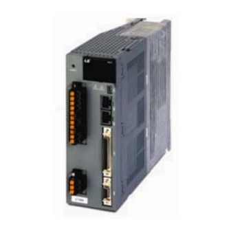
1. Product Components and Signals 1.1.2 Part Names Servo Motor 80 Flange or below Motor Power Cable Motor Encoder Connector Connector Encoder Cable Shaft Encoder Cover Flange Housing Frame Bearing Cap 80 Flange or below(Flat Type) Encoder connector Power connector Shaft Flange... - Page 16 1. Product Components and Signals Servo Drive XDL-L7SA 001□, XDL-L7SA 002□, XDL-L7SA 004□ Display Operation keys (Mode, Up, Down, Set) CN5: USB connector Main power connector (L1, L2, L3) CN4: RS-422 communication DC reactor connector connector (PO, PI) Short circuit when not used CN3: RS-422 communication...
- Page 17 1. Product Components and Signals XDL-L7SA 008□, XDL-L7SA 010□ Display Operation keys (Mode, Up, Down, Set) CN5: USB connector Main power connector (L1, L2, L3) CN4: RS-422 communication DC reactor connector connector (PO, PI) Short circuit when not used CN3: RS-422 communication connector...
- Page 18 1. Product Components and Signals XDL-L7SA 020□, XDL-L7SA 035□ Display Operation keys (Mode, Up, Down, Set) CN5: Main power connector USB connector (L1, L2, L3) CN4: DC reactor connector RS-422 communication (PO, PI) connector Short circuit when not used CN3: RS-422 communication connector...
- Page 19 1. Product Components and Signals XDL-L7SA 050□ Display Operation keys (Mode, Up, Down, Set) CN5: USB Connector CN4: RS-422 Communication connector CN3: RS-422 Communication connector CN1: Control signal connector Control power connector (C1, C2) CN2: Encoder signal connector DC reactor connector (PO, PI) Front cover Short circuit when not used...
-
Page 20: System Configuration
1. Product Components and Signals System Configuration 1.2.1 Overview The XDL-L7 servo system can be configured in various ways depending on its interface with the upper level controller. (1) Position Operation System The servo is run by pulse commands. You can change the location of the servo motor by changing command pulses based on a certain transfer unit. - Page 21 1. Product Components and Signals (3) Torque Operation System The servo is run by torque commands. Analog voltage-based commands are used. Advantages: The servo responds quickly. Precise control is easy. Disadvantage: The upper level controller is complex. (4) Operation Mode The XDL-L7 servo drive can be run in torque, speed and position modes, depending on its interface with the upper level controller.
-
Page 22: Wiring Diagram Of The Entire Cn1 Connector
1. Product Components and Signals 1.2.2 Wiring Diagram of the Entire CN1 Connector Digital Input Note 1) Digital Output ( DO1 ) DC 24V ALARM+ +24V IN ALARM- Note 1) 3.3k Ω ( DO2 ) ( DIA ) STOP READY+ ( DI9 ) READY- ( DI8 ) -
Page 23: Example Of Position Operation Mode Wiring
1. Product Components and Signals 1.2.3 Example of Position Operation Mode Wiring Digital Input Note 1) Digital Output ( DO1 ) DC 24V ALARM+ +24V IN ALARM- 3.3k Ω Note 1) ( DO2 ) ( DIA ) STOP READY+ ( DI9 ) READY- ( DI8 ) CWLIM... -
Page 24: Example Of Speed Operation Mode Wiring
1. Product Components and Signals 1.2.4 Example of Speed Operation Mode Wiring Digital Input Note 1) Digital Output ( DO1 ) DC 24V ALARM+ +24V IN ALARM- 3.3k Ω Note 1) ( DO2 ) ( DIA ) STOP READY+ ( DI9 ) READY- ( DI8 ) CWLIM... -
Page 25: Example Of Torque Operation Mode Wiring
1. Product Components and Signals 1.2.5 Example of Torque Operation Mode Wiring Digital Input Note 1) Digital Output ( DO1 ) DC 24V ALARM+ +24V IN ALARM- 3.3kΩ Note 1) ( DO2 ) ( DI9 ) STOP READY+ ( DI8 ) READY- ( DI7 ) CWLIM... -
Page 26: Examples Of Speed / Position Operation Mode Wiring
1. Product Components and Signals 1.2.6 Examples of Speed / Position Operation Mode Wiring Digital Input Note 1) Digital Output ( DO1 ) DC 24V ALARM+ +24V IN ALARM- Note 1) 3.3k Ω ( DO2 ) ( DIA ) STOP READY+ ( DI9 ) READY-... - Page 27 1. Product Components and Signals 1.2.7 Example of Speed/Torque Mode Wiring Operation Digital Input Note 1) Digital Output ( DO1 ) DC 24V ALARM+ +24V IN ALARM- 3.3k Ω Note 1) ( DO2 ) ( DIA ) STOP READY+ ( DI9 ) READY- ( DI8 ) CWLIM...
- Page 28 1. Product Components and Signals 1.2.8 Example of Position/Torque Operation Mode Wiring Digital Input Note 1) Digital Output ( DO1 ) DC 24V ALARM+ +24V IN ALARM- 3.3k Ω Note 1) ( DO2 ) ( DIA ) STOP READY+ ( DI9 ) READY- ( DI8 ) CWLIM...
-
Page 29: Signal
1. Product Components and Signals Signal 1.3.1 Digital Input Contact Signal Applicable Modes Number Name Details Speed Speed Position Position Speed Torque Factory /Position /Torque /Torque Setting Input contact +24 +24 V IN [V] power SVON Servo ON SPD1 Multi-speed 1 SPD2 Multi-speed 2 SPD3... -
Page 30: Analog Input Contact Signal
1. Product Components and Signals 1.3.2 Analog Input Contact Signal Applicable Modes Name Description Speed Speed Position Number Position Speed Torque /Position /Torque /Torque Analog speed command (-10-+10 [V]) SPDCOM Analog Speed Limit (-10-+10 [V]) Analog Torque Command (-10-+10 [V]) TRQCOM Analog torque limit (-10-+10 [V]) -
Page 31: Monitor Output Signal And Output Power
1. Product Components and Signals 1.3.4 Monitor Output Signal and Output Power Applicable Modes Name Description Speed Speed Position Number Position Speed Torque /Position /Torque /Torque Analog monitor MONIT1 output 1 (-10-+10 [V]) Analog monitor MONIT2 output 2 (-10-+10 [V]) Grounding for analog signals Terminal for +12 [V]... -
Page 32: Encoder Output Signal
1. Product Components and Signals 1.3.6 Encoder Output Signal Applicable Modes Name Description Speed Speed Position Number Position Speed Torque /Position /Torque /Torque Outputs encoder signals received from the motor as signals pre-scaled according to the ratio defined by [P0-14]. (5 [V] line driver method) Outputs encoder Z signals received from the motor. -
Page 33: Installation
2. Installation Installation Servo Motor 2.1.1 Usage Environment Item Requirements Notes Consult with our technical support team to customize the Ambient 0 ∼ 40[℃] product if the temperature in the installation environment is temperature over the given temperature. Ambient 80[%] RH or lower Use the product in steam-free places. -
Page 34: Load Device Connection
2. Installation 2.1.4 Load Device Connection For coupling connection: Make sure that the motor shaft and the load shaft are aligned within the tolerance. 0.03 [㎜] or below (peak to peak) Load shaft Motor shaft 0.03 [㎜] or below (peak to peak) ... -
Page 35: Servo Drive
2. Installation Servo Drive 2.2.1 Usage Environment Item Requirements Notes Caution Ambient 0∼50[℃] Install a cooling fan on the control panel in to keep the temperature surrounding temperature within the required range. Caution Condensation or freezing of moisture inside the drive during Ambient 90[%] RH or prolonged periods of inactivity may damage it. -
Page 36: Installation Inside The Control Panel
2. Installation 2.2.2 Installation Inside the Control Panel Comply with the spaces specified in the following images for installation inside the control panel. 100 mm 40 mm or or longer longer 10 mm or 10 mm or 30 mm or 30 mm or longer longer... -
Page 37: Power Wiring
2. Installation 2.2.3 Power Wiring Make sure that the input power voltage is within the allowed range. Caution Overvoltage can damage the drive. Connecting commercial power to the U, V and W terminals of the drive may cause damage. Be sure to supply power via L1, L2 and L3 terminals. - Page 38 2. Installation...
-
Page 39: Wiring Method
3. Wiring Method Wiring Method Internal Block Diagram 3.1.1 XDL-L7 Drive Block Diagram [XDL-L7SA001□ - XDL-L7SA004□] If you use a DC reactor, connect to the PO and PI pins. If you use external regenerative resistance, connect to the B+ and B pins after removing the B and BI short- circuit pins. -
Page 40: Xdl-L7 Drive Block Diagram [Xdl-L7Sa008□ - Xdl-L7Sa035□]
3. Wiring Method 3.1.2 XDL-L7 Drive Block Diagram [XDL-L7SA008□ - XDL-L7SA035□] NOTE 1) If you use a DC reactor, connect to the PO and PI pins. If you use external regenerative resistance, connect to the B+ and B pins after you remove the B and BI short-circuit pins. -
Page 41: Xdl-L7 Drive Block Diagram [Xdl-L7Sa050□ ]
3. Wiring Method 3.1.3 XDL-L7 Drive Block Diagram [XDL-L7SA050□ ] (Note2) External Regenerative (Note1) Resistance(separately Installed) (Note3) Diode IGBT Three-phase Power Input Regenerative Current Sensor Resistance AC200~230V Thermister Chage Lamp T1 T2 Thermister Internal Regenerative IGBT U and V Control Power Main Power Relay DC Voltage... -
Page 42: Power Wiring
3. Wiring Method Power Wiring 3.2.1 XDL-L7 Drive Wiring Diagram [XDL-L7SA001□ - XDL-L7SA035□] (200~230V) 서보드라이브 Servo Drive R S T 주1) Note 1) DC 리액터 Main DC Reactor Main PO PI 인코더 Encoder Alarm+ +24V Alarm- Note 2) External 주2) 외부... -
Page 43: Xdl-L7 Drive Wiring Diagram [Xdl-L7Sa050□]
3. Wiring Method 3.2.2 XDL-L7 Drive Wiring Diagram [XDL-L7SA050□] Servo Drive R S T (200~230V) DC Reactor Main (Note1) Main PO PI Encoder Alarm+ +24V Alarm- external (Note2) regenerative resistance NOTE 1) It takes approximately one to two seconds until alarm signal is output after you turn on the main power. -
Page 44: Dimensions For Power Circuit Electrical Parts
3. Wiring Method 3.2.3 Dimensions for Power Circuit Electrical Parts XDL- XDL- XDL- XDL- XDL- XDL- XDL- XDL- Name L7SA001□ L7SA002□ L7SA004□ L7SA008□ L7SA010□ L7SA020□ L7SA035□ L7SA050□ 30A Frame 50A Frame MCCB(NFB) 30A Frame 5A (ABE33b/5) 30A Frame 15A (ABE33b/15) 30A Frame 30A (ABE33b/30) 40A(ABE53b (ABE33b/10) - Page 45 3. Wiring Method ( XDL-L7SA004□ or below) Length of strip 7~10[㎜] 0.4~0.5[N·m] 0 . 6 3 . 5 1 0 0 Weidmueller’s SD 0.6x3.5x100 M4 : 1.2[N·m] (XDL-L7SA008□ ~ XDL-L7SA010□) Length of strip 7~10[㎜] 0.4~0.5[N·m] Weidmueller’s SD 0.6x3.5x100 M4 : 1.2[N·m]...
- Page 46 3. Wiring Method (XDL-L7SA020□ ~ XDL-L7SA035□) Length of strip 7~10[㎜] 0.4~0.5[N·m] Weidmueller’s M4 : 1.2[N·m] SD 0.6x3.5x100 1) Refer to the drawings above for wiring with BLF 5.08 or BLZ 7.62HP Series connector. 2) Insert wire into wire-hole when upper screw is untightened and then, use appropriate (-) shaped screwdriver with 0.4 ~ 0.5[N.m] torque to make tight completely.
- Page 47 3. Wiring Method T B 3 T B 2 T B 1 NC : Internal regenerative resistor NC : 내부 회생저항기 Screw for holding lead terminal 리드 단자 고정용 나사 (XDL-L7SA050□) Terminal Block Signals Screw : M4 Screwing torque : 1.2[N·m] Screw : M4 Screwing torque : 1.2[N·m] Screw : M4...
-
Page 48: Example Of Connecting To Plc
3. Wiring Method Example of connecting to PLC 3.3.1 XGT PLC 1. XGF-PO1/2/3A (Open Collector) 3-10... - Page 49 3. Wiring Method 2. XGF-PD1/2/3A (Line Driver) DC 24V I/O Power (Servo Drive) XGF-PD1/2/3A (Line Driver) +24V IN +24V GND24 +24V IN 50 (DO1) ALARM+ Twisted Pair ALARM- (DO3) ZSPD (DO4) BRAKE (DO5) INPOS ALO0 Encoder Z Twisted phase output Pair ALO1 HOME +5V...
- Page 50 3. Wiring Method 3. XGF-PO1/2/3/4H (Open Collector) DC 24V I/O Power (Servo Drive) XGF-PO1/2/3/4H (Open Collector) +24V IN +24V GND24 +24V IN 50 (DO1) PULCOM 49 ALARM+ 1.5K ALARM- P COM P COM (DO3) ZSPD 1.5K (DO4) BRAKE ALO0 ALO1 Encoder Z Twisted ALO2...
- Page 51 3. Wiring Method 4. XGF-PD1/2/3/4H (Line Driver) DC 24V I/O Power (Servo Drive) XGF-PD1/2/3/4H (Line Driver) +24V IN +24V GND24 +24V IN 50 (DO1) P COM ALARM+ Twisted P COM ALARM- Pair (DO3) ZSPD (DO4) BRAKE ALO0 ALO1 Encoder Z Twisted ALO2 phase output...
- Page 52 3. Wiring Method 5. XBF-PD02A (Line Driver) DC 24V I/O Power (Servo Drive) XBF-PD02A (Line Driver) +24V IN +24V GND24 +24V IN 50 주1) (DO1) P COM ALARM+ Twisted P COM ALARM- Pair (DO3) ZSPD (DO4) BRAKE ALO0 ALO1 Encoder Z Twisted ALO2 phase output...
- Page 53 3. Wiring Method 6. XBM-DN**S (Open Collector) DC 24V I/O Power (Servo Drive) XBM-DN**S (Open Collector) +24V IN +24V GND24 +24V IN 50 주1) (DO1) PULCOM 49 ALARM+ 1.5K ALARM- +24V DC24 (DO3) ZSPD Pulse 1.5K (DO4) BRAKE Output Common ALO0 Direction ALO1...
- Page 54 3. Wiring Method 7. XBC/XEC-DNxxH (Open Collector) DC 24V (Servo Drive) XBC/XEC-DNxxH I/O Power (Open Collector) +24V IN +24V GND24 +24V IN 50 (DO1) PULCOM 49 ALARM+ 1.5K ALARM- +24V (DO3) ZSPD Pulse 1.5K %QX0.0.0 (DO4) BRAKE Output Common ALO0 Direction %QX0.0.2 ALO1...
-
Page 55: Timing Diagram
3. Wiring Method Timing Diagram 3.4.1 Timing Diagram During Power Input For XDL-L7 Series, connect single-phase power to the C1 and C2 terminals to supply power to the control circuit, and three-phase power to L1, L2, and L3 to supply power to the main circuit. -
Page 56: Timing Diagram At The Time Of Alarm Trigger
3. Wiring Method 3.4.2 Timing Diagram at the Time of Alarm Trigger When the alarm triggered in the servo drive, it blocks the PWM and the motor stops. Caution After solving the problem that triggered the alarm, and changing the command signal (Servo ON) to OFF, reset the alarm. -
Page 57: Control Signal Wiring
3. Wiring Method Control Signal Wiring 3.5.1 Contact Input Signal Caution 1. There are two input contacts based on the characteristics of individual signals: contact A and contact B. They can be set by [P2-08] and [P2-09]. 2. It is possible to turn each contact on or off forcibly with [Cn-07]. Take extra caution because each contact is automatically turned off when power is off. -
Page 58: Contact Output Signal
3. Wiring Method 3.5.2 Contact Output Signal Caution 1. There are two output contacts based on the characteristics of individual signals: contact A and contact B. They can be set by [P2-10]. 2. It is possible to turn each contact on or off forcibly with [Cn-08]. Take extra caution because each contact is automatically turned off when power is off. -
Page 59: Analog Input/Output Signals
3. Wiring Method 3.5.3 Analog Input/Output Signals 1. Keep GND as 0 [V] of control power. 2. Keep the input signal command voltage within ±10 [V], and input impedance at 22 [㏀]. 3. Output signal voltage for Monitor 1 (No. 28) and Monitor 2 (No. 29) is ±10 [V]. Configure wiring as shown in the following image when you adjust analog input with parameter resistance by using power supplied by the drive. -
Page 60: Pulse Train Input Signal
3. Wiring Method 3.5.4 Pulse Train Input Signal (1) Line Driver (5 [V]) Pulse Input Servo Drive Upper level controller Twisted Pair Shield Wire Line driver Line receiver (2) Open Collector (24 [V]) Pulse Input Servo Drive Upper level controller GND24 +24 [V] Pulse COM... -
Page 61: Encoder Output Signal
3. Wiring Method (4) PNP Open Collector Pulse Command NOTE 1) When using 24 [V] power: Resistance R = 1.5 [kΩ], 1/2 [W] When using 12 [V] power: Resistance R = 560-680 [Ω], 1/2 [W] When using 5 [V] power: Resistance R = 100-150 [Ω], 1/2 [W] 3.5.5 Encoder Output Signal Connect the GND terminal of the upper level controller and the GND terminal of CN1 because encoder signals are output based on the GND of control power. -
Page 62: Quadrature Encoder Signaling Unit (Cn2) Wiring
3. Wiring Method Quadrature Encoder Signaling Unit (CN2) Wiring 3.6.1 XLCS-E AS Cable 3.6.2 XLCS-E BS Cable 3-24... -
Page 63: Serial Encoder Signaling Unit (Cn2) Wiring
3. Wiring Method Serial Encoder Signaling Unit (CN2) Wiring 3.7.1 XLCS-E CS Cable 3.7.2 XLCS-E DS Cable 3-25... - Page 64 3. Wiring Method 3.7.3 XLCS-E ES Cable Servo Motor Servo Drive 인코더 Encoder Cable Connector(CN2) Maker - 3M 10314-52A0-008 10114-3000VE Connector Frame Tyco Connector (7Ciruits) 3-26...
-
Page 65: Multi Turn Encoder Signal Unit(Cn2) Wiring
3. Wiring Method Multi Turn Encoder signal unit(CN2) wiring 3.8.1 XLCS-E CS1 Cable AWG24 4Pair Twist Servo Drive Shield Wire Servo Motor BAT+ BAT- Encoder Cable Connector (CN2) Maker - 3M 10314-52A0-008 10114-3000VE Cable Frame Connector MS3108S20-29S 3.8.2 XLCS-E DS1 Cable AWG24 4Pair Twist Servo Motor Servo Drive... - Page 66 3. Wiring Method 3.8.3 XLCS-E ES1 Cable Servo Motor Servo Drive BAT+ BAT_ 인코더 Encoder Cable Connector(CN2) Maker - 3M 10314-52A0-008 10114-3000VE Frame Connector Tyco Connector (7 Circuits) 3-28...
-
Page 67: Transmission Of Absolute Encoder Data
3. Wiring Method Transmission of Absolute Encoder Data 3.9.1 Transmission of Absolute Encoder Data Upon the absolute encoder's request for absolute data, the data of the absolute encoder are transmitted to the upper level controller in the form of quadrature pulses through the output of the encoder output signals, AO and BO. -
Page 69: Parameters
4. Parameters Parameters How to Use the Loader 4.1.1 Names and Functions of Each Parts Display 5-digit FND data. Digit 5 Digit 4 Digit 3 Digit 2 Digit 1 Displays the decimal point. E.g.) 123.4 [MODE]: Change display mode. [/LEFT]: Move to another data digit. In the case of 16 bits, the minus symbol is used. -
Page 70: Status Summary Display
4. Parameters 4.1.2 Status Summary Display (1) Status Summary Display in Speed Mode ① Example of the OFF status of the servo in speed control mode DIGIT 3-1: Displays the current status of the servo. bb - Servo OFF ... - Page 71 4. Parameters (2) Servo Operation Status Summary Display List The following list explains the operation status summary display of different modes of the servo. Operation Status Function Notes Screen Displays the servo's OFF status when in the position mode. Displays the servo's ON status when in position mode.
-
Page 72: Parameter Handling
4. Parameters 4.1.3 Parameter Handling (1) Parameter Movement Example of changing speed control mode to position control mode ([P0-03]: 00001 -> 00002) If the alarm does not go off at the starting operation, the speed operation mode [S=bb] indicating operation status is displayed. - Page 73 4. Parameters (2) Example of changing speed control mode to position control mode ( [P0-03]: 00001 -> 00002 ) Loader Displays Keys to Use What to Do Displays the speed control mode with main power and control power permitted. Press [MODE] to move to [P0-00]. Press [UP] or [DOWN] to move to [P0- 03].
- Page 74 4. Parameters (3) Example of changing speed proportional gain 2 ([P1-07]: 200 [rad/s] -> 500 [rad/s]) Loader Displays Keys to Use What to Do Displays the speed control mode with main power and permitted control power. Press [MODE] to move to [P1-00]. Press [UP] or [DOWN] to move to [P1- 07].
- Page 75 4. Parameters (4) Example of changing DAC output offset 1 ([P0-19]: 0 [Unit/V] -> -500 [Unit/V]) Loader Displays Keys to Use What to Do Displays the speed control mode with main power and control power permitted. Press [MODE] to move to [P0-00]. Press [UP] or [DOWN] to move to [P0- 19].
-
Page 76: Data Display
4. Parameters 4.1.4 Data Display (1) Binary ① Minimum (0b00000) ② Maximum (0b11111) (2) Hex ① Minimum (0x0000) ② Maximum (0xFFFF) (3) 16-bit Unsigned Integer ① E.g.) 0 ② E.g.) +1234 (4) 16-bit Signed Integer ① E.g.) -1234 ② E.g.) +5678 ①... - Page 77 4. Parameters (6) 32-bit Signed Integer Data Display ① Minimum (-2147483648) Display upper two digits Display middle four digits Display lower four digits ② Maximum (2147483647) Display upper two digits Display middle four digits Display lower four digits E.g.) [St-16]: Displayed as Upper = 0, Middle = 0012, and Lower = 2071 Order Loader Displays...
-
Page 78: External Input Contact Signal Display [St-14]
4. Parameters 4.1.5 External Input Contact Signal Display [St-14] You can check whether the ON/OFF status of digital input/output signals that access the servo drive are on or off. (1) External Input Signal Display The positions of the seven segment LEDs and CN1 connector pins correspond as follows. If an LED that corresponds to a pin is turned on/off, it indicates ON/OFF accordingly. -
Page 79: External Input Signal And Logic Definition
4. Parameters 4.1.6 External Input Signal and Logic Definition The following describes how to allocate input signals and how to view them. (1) Input Signal Allocation XDL-L7 Drive allows for the allocation of a total of 19 input contact functions to 10 hardware contacts. - Page 80 4. Parameters Signal Name Alwa CN1 Pin Default Allocation Number Input Input Allo Default Signal Parameter Signal Alloc cati setting Definition Allocation ated Servo ON SVON [P2-00].Set Digit 1 Multi-speed 1 SPD1 [P2-00]. Set Digit 2 [P2-00] 0x4321 Multi-speed 2 SPD2 [P2-00].
- Page 81 4. Parameters (2) Example of Changing Input Signal Allocation The input signal definition can be changed in [P2-00], [P2-01], [P2-02], [P2-03], and [P2-04]. The input signal logic definition can be changed in [P2-08] and [P2-09]. Allocate input signals as shown in the following table: Input Signal Input Allocation Number 4-13...
- Page 82 4. Parameters Signal Name Alwa CN1 Pin Default Allocation Number Input Value Input Alloc Signal After Parameter Signal Alloc ation Definition Changing Allocation ated Servo ON SVON [P2-00].Set Digit 1 Multi-speed 1 SPD1 [P2-00]. Set Digit 2 [P2-00] 0x0321 Multi-speed 2 SPD2 [P2-00].
- Page 83 4. Parameters Examples of Changing Input Signal Allocation The following is an example of changing input signal allocation. The allocation signals of SVON (CN1-47) and STOP (CN1-48) can be switched in the following sequence. Before Changing After Changing [P2-00]: [P2-02]: Order Loader Displays...
- Page 84 4. Parameters (3) Input signal logic definition XDL-L7 Drive allows for defining the logic of input signals for 10 hardware contacts from DI1 to DIA through parameters [P2-08] and [P2-09]. The logic of input signals as set in the factory is as follows. Input signal logic definition number Input signal logic definition Signal Name...
- Page 85 4. Parameters (4) Example of Changing Input Signal Logic Definitions Input signal logic definitions can be changed in [P2-08] and [P2-09]. When input signals are allocated as below, settings will be done as shown in table below. Input signal logic definition Input signal logic definition number Signal Name CN1 Pin Default Allocation Number...
- Page 86 4. Parameters Examples of changing input signal logic definitions The table below shows examples of changing input signal logic definitions. The sequence of changing logic signal contact A of SVON (CN1-47) to contact B and logic signal contact B of CCWLIM (1-20) to contact A is as follows. Before changing After changing [P2-08]:...
-
Page 87: External Output Contact Signal Display [St-15]
4. Parameters 4.1.7 External Output Contact Signal Display [St-15] You can check whether the ON/OFF status of digital input/output signals that access the servo drive are on or off. (1) External Output Signal Display The positions of the seven segment LEDs and CN1 connector pins correspond as follows. If an LED that corresponds to a pin is turned on/off, it indicates ON/OFF accordingly. -
Page 88: External Output Signal And Logic Definition
4. Parameters 4.1.8 External Output Signal and Logic Definition The following explains output signal allocation and the method of checking allocation status. (1) Output Signal Allocation Output signal definition: [P2-05], [P2-06], [P2-07] Output signal logic definition: [P2-10] The default output signal allocation is as follows: Output Signal Output Allocation Number... - Page 89 4. Parameters (2) Examples of Changing Output Signal Allocation The output signal definition can be changed in [P2-05], [P2-06], and [P2-07]. The output signal logic definition can be changed in [P2-10]. Allocate output signals as in the following table: ...
- Page 90 4. Parameters Example of Changing Output Signal Allocation The following is an example of output signal allocation change. The sequence of switching the allocation signals of ALARM (CN1-38/39) and ZSPD (CN1- 43) is as follows: Before Changing After Changing [P2-05]: Loader Window Order...
- Page 91 4. Parameters (3) Output Signal Logic Definition Output signal logic definition: [P2-10] The logic of output signals as shipped from the factory is as follows. Output signal logic definitions Output signal logic definition number DO1(Contact A/Contact B) DO2(Contact A/Contact B) DO3(Contact A/Contact B) DO4(Contact A/Contact B) DO5(Contact A/Contact B)
- Page 92 4. Parameters (4) Examples of Changing Output Signal Logic Definition Output signal logic definitions can be changed at [P2-10] Set output signals as shown in the table below when they are allocated as below. Output signal logic definitions Output signal logic definition number DO1(Contact A/Contact B) DO2(Contact A/Contact B)
- Page 93 4. Parameters Example of Changing Output Signal Allocation The following is an example of output signal allocation change. The sequence of switching the allocation signals of ALM (CN1-38/39) and ZSPD (CN1-43) is as follows: Before Changing After Changing [P2-05]: Loader Window Order Keys to Use...
-
Page 94: Parameter Description
4. Parameters Parameter Description 4.2.1 Parameter System There are a total of eight groups of parameters. Each group is explained in the following table: Move to Parameter Parameter Another Initial Screen Details Number Group Name Parameter E.g.) In speed mode Status Summary Displays the status Display... -
Page 95: Operation Status Display Parameter
4. Parameters 4.2.2 Operation Status Display Parameter For detailed information, refer to "4.3 Operation Status Display." “**” Modification is not possible with the servo on & Power reset parameter. “*” Parameter that cannot be modified with the servo on Parameter Unit Initial Applic... - Page 96 4. Parameters Parameter Unit Initial Applic Details ation mode Code Name Minimum Maximum Accumulated Displays the currently accumulated load factor against the maximum accumulated load factor as a overload rate St-09 percentage. Accumulated -300.0 300.0 (Details: Refer to “4.3.4 Torque and Load Display.”) overload Instantaneous Displays the instantaneous maximum load factor...
- Page 97 4. Parameters Parameter Unit Initial Applic Details ation mode Code Name Minimum Maximum Internal Displays the internal temperature sensor value. [℃] temperature St-19 Room temperature Rated motor Displays the rated speed of the currently [RPM] speed installed motor. St-20 Rated RPM 10000 Maximum motor Displays the maximum speed of the currently...
-
Page 98: System Setting Parameter
4. Parameters 4.2.3 System Setting Parameter For detailed information, refer to "4.4.1 System Parameter Setting." “**” Modification is not possible with the servo on & Power reset parameter. “*” Parameter that cannot be modified with the servo on Parameter Unit Initial Appli Details... - Page 99 4. Parameters Applica Parameter Unit Initial Details tion Code Name Minimum Maximum mode Main power Sets main power input. 0b00000 input mode DIGIT 1-> 0: Single-phase power 1: 3-phase power input P0-06 Caution: Using single-phase power may lower motor output. Power fail mode 0b00000 0b11111...
- Page 100 4. Parameters Applica Parameter Unit Initial Details tion Code Name Minimum Maximum mode DB control mode Sets DB control mode. 0: Hold after DB stop 1: Release after DB stop *P0-16 2: Release after free run stop DB control mode ...
- Page 101 4. Parameters Parameter Unit Initial Applica Details tion Maximu Code Name Minimum mode DAC output Sets offset for 1-2 analog output channels. offset 1 [Unit/V] Speed: [RPM] (MONIT1) Torque: [%] P0-19 Position command frequency: [0.1 Kpps] DAC output offset 1 -1000 1000...
-
Page 102: Control Setting Parameter
4. Parameters 4.2.4 Control Setting Parameter For detailed information, refer to "4.4.2 Control Parameter Setting." “**” Modification is not possible with the servo on & Power reset parameter. “*” Parameter that cannot be modified with the servo on Parameter Unit Initial Applica Details... - Page 103 4. Parameters Applica Parameter Unit Initial Details tion Code Name Minimum Maximum mode Speed Sets speed control proportional gain 2. proportional gain [rad/s] (Details: Refer to “4.4.2 Control Parameter P1-07 Setting.”) Speed P gain 2 5000 Speed integral Sets speed control integral time constant 1. [ms] time constant 1 (Details: Refer to “4.4.2 Control Parameter...
- Page 104 4. Parameters Parameter Unit Initial Applica Details tion Code Name Minimum Maximum mode Gain transfer Sets gain transfer mode. [0x0F (DIGIT 1)] 0x00 mode 0: Use only gain 1. 1: ZSPD automatic gain transfer In case of zero speed, transfer from gain 1 to gain In the opposite case, transfer from gain 2 to gain 1.
- Page 105 4. Parameters Parameter Unit Initial Applica Details tion Code Name Minimum Maximum mode Torque control Sets speed limit mode during torque control. speed limiting 0: Limit to [P1-23]. 1: Maximum motor speed mode P1-22 2: Analog speed command Velocity limit 3: Limited to the smaller value between the value of switch [P1-23] and the analog speed command.
-
Page 106: Input/Output Setting Parameter
4. Parameters 4.2.5 Input/Output Setting Parameter For detailed information, refer to "4.4.3 Analog Input/Output Parameter Setting" and "4.4.4 Input/Output Contact Parameter Setting." “**” Modification is not possible with the servo on & Power reset parameter. “*” Parameter that cannot be modified with the servo on Parameter Unit Initial... - Page 107 4. Parameters Applica Parameter Unit Initial Details tion Code Name Minimum Maximum mode Input signal logic Define CN1 connector logic for a digital input 0b10001 definition 2 signal.(0: Contact B, 1: Contact A) Initial input logic definitions [P2-09]DIGIT 1 = DI6 (CN1 #46) (Contact A) ...
- Page 108 4. Parameters Applica Parameter Unit Initial Details tion Code Name Minimum Maximum mode Analog speed Sets offset for analog speed commands. [mV] offset (Details: Refer to “4.4.3 Analog Input/Output P2-18 Parameter Setting.”) Analog speed -1000 1000 command offset Sets voltage range for the clamp operation of the Zero speed clamp [mV] analog zero speed command.
-
Page 109: Speed Operation Setting Parameter
4. Parameters 4.2.6 Speed Operation Setting Parameter For detailed information, refer to "4.4.5 Speed Operation Parameter Setting." “**” Modification is not possible with the servo on & Power reset parameter. Parameter Unit Initial Details Code Name Minimum Maximum Speed command 1 [RPM] Sets 1-6 speed commands based on the speed P3-00... - Page 110 4. Parameters Parameter Unit Initial Details Code Name Minimum Maximum Program JOG operation Sets operation speed/operation time for programs 1 [RPM] speed 1 to 4 during program JOG operation [Cn-01]. P3-13 A test run repeats from step 1 to step 4. Program jog speed 1 -6000 6000...
-
Page 111: Position Operation Setting Parameter
4. Parameters 4.2.7 Position Operation Setting Parameter For detailed information, refer to "4.4.6 Position Operation Parameter Setting." “**” Modification is not possible with the servo on & Power reset parameter. “*” Parameter that cannot be modified with the servo on Parameter Unit Initial... - Page 112 4. Parameters Parameter Unit Initial Details Code Name Minimum Maximum Electronic gear ratio Sets electronic gear ratio numerator/denominator 1, 1000 numerator 1 2, 3, and 4. *P4-01 Electric gear num.1 2^21 Electronic Gear Ratio EGEAR EGEAR Electronic Electronic gear ratio Gear Ratio Numerator / 1000...
- Page 113 4. Parameters Parameter Unit Initial Details Maximu Code Name Minimum Backlash Sets backlash compensation in position compensation operation. Sets backlash compensation by converting the amount of backlashes to number of pulses if the position changes because of backlashes P4-13 caused by position operation. Backlash 10000 Sets in the opposite direction according to the...
-
Page 114: Operation Handling Parameter
4. Parameters 4.2.8 Operation Handling Parameter “**” Modification is not possible with the servo on & Power reset parameter. “*” Parameter that cannot be modified with the servo on Parameter Unit Initial Details Minimu Maximu Code Name Manual JOG operation The drive performs manual JOG operation by itself. - Page 115 4. Parameters Parameter Unit Initial Details Code Name Minimum Maximum Get alarm history Check the saved alarm code history. [UP] or [DOWN]: Reads alarm codes. E.g.) Recent first history [AL-42]: RST_PFAIL occurs. Cn-03 Get alarm history 01: Latest alarm ...
- Page 116 4. Parameters Parameter Unit Initial Details Minimu Maximu Code Name Auto speed command Calibrates the offset of analog speed offset correction commands automatically. The possible voltage range is from -1 V to 1 If offset voltage exceeds this range, [oVrnG] Cn-10 is displayed and there is no calibration.
- Page 117 4. Parameters Parameter Unit Initial Details Maximu Code Name Minimum Absolute encoder reset Resets the absolute encoder. Cn-14 (Details: Refer to "5.2 Handling.") Abs encoder reset Reset the instantaneous maximum load factor to Max load clear [UP]: Displays the + forward maximum load factor.
-
Page 118: Operation Status Display
4. Parameters Operation Status Display 4.3.1 Status Display [St-00] Refer to "4.1.2 Status Summary Display." 4.3.2 Speed Display 1. Current operation speed [St-01] Displays the current operation speed in [RPM]. 2. Current command speed [St-02] Displays the current command speed in [RPM]. 4.3.3 Position Display 1. -
Page 119: I/O Status Display
4. Parameters 5. Torque limit [St –11] Displays the maximum torque that the servo motor can output as a percentage of the rated torque. 6. DC link voltage [St–12] The DC link voltage of the standard drive that uses 220 [V] is approximately 300 [V]. ... -
Page 120: Version Display
4. Parameters 4.3.7 Version Display 1. Software version display [St-25] Displays the version of the currently installed software. 4-52... -
Page 121: Parameter Setting
4. Parameters Parameter Setting 4.4.1 System Parameter Setting 1. Motor ID setting [P0-00] Refer to motor ID: xxx on the label. 2. Encoder setting Encoder type [P0-01] the table below. of the label attached to the motor Refer to encoder content ... - Page 122 4. Parameters 4. System ID setting An ID can be given to the servo if RS422 communication and BUS communication are used for communication with the servo. Communication-related options are required in this case. Communication speed setting [P0-04] You can select the baud rate, the communication speed of RS422. ...
- Page 123 4. Parameters When an encoder signal is output from the servo to the outside, its output pulses are pre-scaled as the value of encoder output scaling[P0-14] E.g.) Set the value of encoder output scaling[P0-14] in a motor whose encoder pulse is 3,000 [ppr].
-
Page 124: Control Parameter Setting
4. Parameters 1 : 0~+10V DIGIT 5 -> Sets EEPROM save function in communication. 0: EEPROM use. 1: EEPROM not for use 17. DAC output setting There are 2 kinds of DAC output, each of which is made every 200 [usec] according to the condition of used data. - Page 125 4. Parameters (1) Inertia Ratio Setting [P1-00] An inertia ratio shall be set by calculating load inertia from the machine system and rotor inertia from the motor specification table. Setting inertia ratio against load is an important control parameter for the operation of the servo.
- Page 126 4. Parameters Feedforward gain [P1-04]: Calculate the gradient with the differential value of the position command. Reduce time to target position by adding the speed command to the gradient. If the resultant value is too big, overshooting or instability might occur in position control. Therefore, it is important to gradually increase the value from a small value while watching the test drive.
- Page 127 4. Parameters Speed Command speed High Time Speed feedback filter time constant [P1-11]: If the speed of the motor changes because of vibration of the drive system, or vibration occurs due to gain when there is too much load inertia, you can control the vibration by applying a filter to speed feedback.
- Page 128 4. Parameters (7) Gain 1<->Gain 2 Conversion Time Setting [P1-16] Set gain transfer time during operation. When converting gain 1 to gain 2 and gain 2 to gain 1, conversion is scheduled according to the set time. (8) P / PI Conversion Mode Setting [P1-15 DIGIT 2] Set P and PI control conversion modes.
-
Page 129: Analog Input/Output Parameter Setting
4. Parameters 4.4.3 Analog Input/Output Parameter Setting (1) Analog Speed Scale Setting Analog speed scale [P2-17]: Set the analog speed command of 10 [V] in the unit of [RPM]. The maximum value is the maximum motor speed. Analog speed command offset [P2-18]: There are cases where a certain level of voltage remains on the analog signal access circuit, even at the 0 speed command. -
Page 130: Input/Output Contact Point Parameter Setting
4. Parameters 4.4.4 Input/Output Contact Point Parameter Setting (1) Position Operation Parameter Setting Position reached output range [P2-11]: If the error pulse, which is the difference between the command position pulse and the follow position pulse, reaches this range, a signal is output to indicate that the position has been decided. - Page 131 4. Parameters (2) Speed Operation Parameter Setting Speed Command speed Range of output for speed reached [P2-13] Zero speed output Time range [P2-12] Zero speed (ZSPD) Speed reached (INSPD) Zero speed output range [P2-12]: When the current speed becomes lower than the set speed, the zero speed signal is output.
- Page 132 4. Parameters (4) Position Pulse Clear Mode [P2-16] Set the operation of position pulse clear mode in position operation mode. Setting Operation Operate only on the edge where the contact point turns from off to on. (Do not operate when it is off or on.) Operate immediately at contact point on_ Level.
-
Page 133: Speed Operation Parameter Setting
4. Parameters 4.4.5 Speed Operation Parameter Setting (1) Speed Command [P3-00]-[P3-06] You can adjust operation speed in [RPM]. Operation speed is determined by speed command input contact points. SPD1 SPD2 SPD3 Speed Control Analog speed command Digital speed command Digital speed command Digital speed command Digital speed command Digital speed command... -
Page 134: Position Operation Parameter Setting
4. Parameters 4.4.6 Position Operation Parameter Setting (1) Input Pulse Logic [P4-00] Set type of the position command input pulse and rotation method per logic. 0: A+B 1: CW+CCW, positive logic 2: Pulse + sign, positive logic ... - Page 135 4. Parameters (2) Electronic Gear Ratio [P4-01] ~ [P4-08] The electronic gear ratio is the numerator/denominator form of the relation between the position command input pulse and the motor encoder pulse. It is important to set the ratio so that there is no error during position operation. The following describes how to set it: * Electronic gear ratio = transmission per input pulse x number of pulses per motor rotation / transmission per motor rotation e.g.) If deceleration ratio is 1/2, ball screw lead is 10 [㎜], and encoder pulse is 3000 in the...
-
Page 136: Alarms And Warnings
4. Parameters If the offset is two, the electronic gear ratio for operation changes from 12000/5000 to 12002/5000. Also, if the offset is -2, the electronic gear ratio for operation changes from 12000/5000 to 11998/5000. Alarms and Warnings 4.5.1 Servo Alarm Status Summary Display List If an alarm triggers, the malfunction signal output contact point (ALARM) turns off and the dynamic brake stops the motor. - Page 137 4. Parameters Alarm Name Details What to inspect Code Motor cable open Motor cable disconnection Motor wiring Serial encoder Check for incorrect wiring of the serial Encoder comm. communication error encoder cable. Encoder cable Check whether the encoder cable is Encoder cable open disconnection disconnected.
-
Page 138: Servo Warning Status Summary Display List
4. Parameters 4.5.2 Servo Warning Status Summary Display List If a warning code is displayed as the current operation status [St-00], the servo drive is operating abnormally. Check what needs to be inspected for the issue. Warning State Name Cause What to inspect (CODE) If the [P0-06] DIGIT 2 is set to 1, the... -
Page 139: Motor Type And Id (To Be Continued On The Next Page)
4. Parameters Motor Type and ID (to be continued on the next page) Model Name Watt Notes Model Name Watt Notes SAR3A SE13G 1300 SAR5A SE17G 1700 SA01A HE09A Hollow type SA015A HE15A 1500 Hollow type SB01A SF30A 3000 SB02A SF50A 5000 SB04A... - Page 140 4. Parameters Model Name Watt Notes Model Name Watt Notes SG85G 8500 FF30A 3000 SG110G 11000 FF50A 5000 SG150G 15000 FF22D 2200 FF35D 3500 FB01A FF55D 5500 FB02A FF75D 7500 FB04A FF12M 1200 FF20M 2000 FC04A FF30M 3000 FC06A FF44M 4000 FC08A FF20G...
- Page 141 4. Parameters Model Name Watt Notes Model Name Watt Notes DB03D DB06D DB09D DC06D DC12D DC18D DD12D DD22D DD34D DE40D 1257 DE60D DFA1G 1728 DFA6G 2513 4-73...
-
Page 143: Handling And Operation
5. Handling and Operation Handling and Operation What to Check Before Operation Thoroughly check the following lists during test drive to prevent injury or product damage in servo motor. 5.1.1 Wiring Check 1. Is the voltage (AC 200 [V]) appropriate for the power input terminals? 2. -
Page 144: System Parameter Check
5. Handling and Operation 5.1.5 System Parameter Check 1. Is the motor ID setting [P0-00] in good condition? 2. Are the encoder type [P0-01] and the encoder pulse [P0-02] in good condition? 3. Is control gain set to an appropriate value? *Note: Refer to "Appendix 2 Test Drive Procedure."... -
Page 145: Handling
5. Handling and Operation Handling 5.2.1 Manual JOG Operation [Cn-00] The drive performs manual JOG operation by itself. 1. Press [SET] in [Cn-00] and [JoG] is displayed. 2. Press [SET] and [SV-on] is displayed and the servo turns on for operation. If an alarm triggers, check wiring and other possible causes before restarting. - Page 146 5. Handling and Operation [Example of handling manual JOG operation] Order Loader Displays Keys to Use What to Do Displays the speed control mode with main power and control power permitted. Press [MODE] to move to [Cn- 00]. Press [SET] to enter manual JOG operation.
-
Page 147: Program Jog Operation [Cn-01]
5. Handling and Operation 5.2.2 Program JOG Operation [Cn-01] Continuously operates according to the program already set. 1. Press [SET] in [Cn-01] and [P-JoG] is displayed. 2. Press [SET] and [run] is displayed. The program JOG operation starts after the servo is turned on. (If an alarm triggers at this moment, check the wiring of the servo and other possible causes before restarting.) 3. -
Page 148: Alarm Reset [Cn-02]
5. Handling and Operation 5.2.3 Alarm Reset [Cn-02] Reset the alarm that went off. 1. Contact alarm reset: If you turn on ALMRST among input contacts, the alarm is reset and becomes normal. 2. Operation alarm reset: If you press [SET] in the alarm reset [Cn-02] parameter among operation handling parameters, [ALrst] is displayed. -
Page 149: Reading Alarm History [Cn-03]
5. Handling and Operation 5.2.4 Reading Alarm History [Cn-03] Check the saved alarm history. [Example of getting alarm history] Order Loader Displays Keys to Use What to Do Displays the speed control mode with main power and control power permitted. Press [MODE] to move to [Cn-00]. -
Page 150: Alarm History Reset [Cn-04]
5. Handling and Operation 5.2.5 Alarm History Reset [Cn-04] Delete all currently stored alarm history. [Example of alarm history reset] Order Loader Displays Keys to Use What to Do Displays the speed control mode with main power and control power permitted. -
Page 151: Auto Gain Tuning [Cn-05]
5. Handling and Operation 5.2.6 Auto Gain Tuning [Cn-05] Perform automatic tuning operation. 1. Press [SET] from the [Cn-05] parameter and [Auto] is displayed. 2. Press [SET] and [run] is displayed and automatic gain tuning starts. If an alarm triggers at this moment, check the wiring of the servo and other possible causes before restarting. -
Page 152: Phase Z Search Operation [Cn-06]
5. Handling and Operation 5.2.7 Phase Z Search Operation [Cn-06] Perform phase Z search operation. 1. Press [SET] in [Cn-06] and [Z-rtn] is displayed. 2. Press [SET] and [run] is displayed and the servo turns on. 3. While you hold down UP, the motor keeps turning forward (CCW) until it finds the phase Z position of the encoder. -
Page 153: Input Contact Forced On/Off [Cn-07]
5. Handling and Operation 5.2.8 Input Contact Forced ON/OFF [Cn-07] The drive forcibly turns on/off the input contact without an upper level controller or I/O jig. (1) Input Contact Forced ON/OFF Setting The positions of the seven segment LEDs and CN1 contacts correspond as follows. If an LED that corresponds to a contact is turned on/off, it indicates ON/OFF accordingly. - Page 154 5. Handling and Operation (2) Example of Input Contact Forced ON/OFF (SVON ON → EMG ON → EMG OFF → SVON OFF) [Example of handling input contact forced ON/OFF] Order Loader Displays Keys to Use What to Do Press [MODE] to move to [Cn-00]. Press [UP] or [DOWN] to move to [Cn-07].
-
Page 155: Output Contact Forced On/Off [Cn-08]
5. Handling and Operation 5.2.9 Output Contact Forced ON/OFF [Cn-08] Without an upper level controller or I/O jig, the drive forcibly turns on/off the output contact. (1) Output Contact Forced ON/OFF Setting The positions of the seven segment LEDs and CN1 contact correspond as follows. If an LED that corresponds to a contact is turned on/off, it indicates ON/OFF accordingly. - Page 156 5. Handling and Operation (2) Example of Output Contact Forced ON/OFF (BRAKE OFF) [Example of handling output contact forced ON/OFF] Order Loader Displays Keys to Use What to Do Press [MODE] to move to [Cn-00]. Press [UP] or [DOWN] to move to [Cn-08].
-
Page 157: Parameter Reset [Cn-09]
5. Handling and Operation 5.2.10 Parameter Reset [Cn-09] Reset parameter data. [Example of initializing parameters] Order Loader Displays Keys to Use What to Do Displays the speed control mode with main power and control power permitted. Press [MODE] to move to [Cn-00]. Press [UP] or [DOWN] to move to [Cn-09]. -
Page 158: Automatic Speed Command Offset Correction [Cn-10]
5. Handling and Operation 5.2.11 Automatic Speed Command Offset Correction [Cn-10] This calibrates the offset of analog speed commands automatically. The range of adjustable speed command analog voltage is from +1 V to -1 V. If offset voltage exceeds this range, [oVrnG] is displayed and calibration is not allowed. You can check the corrected offset value in the analog speed offset [P2-18]. -
Page 159: Automatic Torque Command Offset Correction [Cn-11]
5. Handling and Operation 5.2.12 Automatic Torque Command Offset Correction [Cn-11] This calibrates the offset of analog torque commands automatically. The range of adjustable torque command analog voltage is from +1 V to -1 V. If offset voltage exceeds this range, [oVrnG] is displayed and calibration is not allowed. You can check the corrected offset value in the analog torque offset [P2-21]. -
Page 160: Manual Speed Command Offset Correction [Cn-12]
5. Handling and Operation 5.2.13 Manual Speed Command Offset Correction [Cn-12] This calibrates the offset value of analog speed commands manually. Example: -10 The range of adjustable speed command analog voltage is from +1 V to -1 V. If offset voltage exceeds this range, [oVrnG] is displayed and calibration is not allowed. -
Page 161: Manual Torque Command Offset Correction [Cn-13]
5. Handling and Operation 5.2.14 Manual Torque Command Offset Correction [Cn-13] This calibrates the offset value of analog torque commands manually. The range of adjustable torque command analog voltage is from +1 V to -1 V. If offset voltage exceeds this range, [oVrnG] is displayed and calibration is not allowed. You can check the corrected offset value in the analog torque command offset [P2-21]. -
Page 162: Absolute Encoder Reset [Cn-14]
5. Handling and Operation 5.2.15 Absolute Encoder Reset [Cn-14] Initialize values of [St-16], [St-17],[St-18] to “0” when It is connected with Multi turn Motor. [Example of how to use Absolute Encoder Reset] Orde Loader Displays Keys to Use What to Do Press [MODE] key to display [Cn-00]. -
Page 163: Instantaneous Maximum Load Factor Initialization [Cn-15]
5. Handling and Operation 5.2.16 Instantaneous Maximum Load Factor Initialization [Cn-15] Reset the instantaneous maximum load factor to 0. [Example of initializing the instantaneous maximum load factor] Order Loader Displays Keys to Use What to Do Press [MODE] to display [Cn-00]. Press [UP] or [DOWN] to move to [Cn-15]. -
Page 164: Parameter Lock [Cn-16]
5. Handling and Operation 5.2.17 Parameter Lock [Cn-16] Lock or Unlock whole parameter. [Example of locking or unlocking parameter] Order Loader Displays Keys to Use What to Do Press [MODE] to display [Cn-00]. Press [UP] or [DOWN] to move to [Cn-16]. -
Page 165: Current Offset[Cn-17]
5. Handling and Operation 5.2.18 Current Offset[Cn-17] Store existing current offset value into [P0-27] ~ [P0-28] parameter. [Example of setting current offset value] Order Loader Displays Keys to Use What to Do Press [MODE] to display [Cn-00]. Press [UP] or [DOWN] to move to [Cn-17]. -
Page 167: Communication Protocol
6. Communication Protocol Communication Protocol Overview and Communication Specifications 6.1.1 Overview The XDL-L7 servo drive uses RS-422 serial communication. By connecting it to a PC or an upper level controller, you can test drive it or change gain tuning and parameters. You can also operate or handle communication of up to 32 axes by connecting multiple XDL- L7 servo drives via a multi-drop method. -
Page 168: Communication Specifications And Cable Access Rate
6. Communication Protocol 6.1.2 Communication Specifications and Cable Access Rate (1) Communication Specifications Item Specifications Communication standard ANSI/TIA/EIA-422 standard Communication protocol MODBUS-RTU Data bit 8 bit Data Stop bit 1 bit Type Parity None Synchronous method Asynchronous 9600 /19200/38400/57600 [bps] Transmission speed [P0-04] can be selected. -
Page 169: Communication Protocol Base Structure
6. Communication Protocol Communication Protocol Base Structure The communication of the XDL-L7 servo drive complies with the international standard MODBUS-RTU protocol. For information about items not covered in this manual, refer to the following standard. (Related standard: Mudbugs application protocol specification 1.1b, 2006.12.28) Also, the concept of sending and receiving in this manual is based on the host. - Page 170 6. Communication Protocol (3) Protocol Packet Code Node ID Indicates the exchange number of the servo drive to send. Set the exchange number of the servo drive to [P0-05]. Function Code The following are the Modbus-RTU standard function codes supported by the XDL-L7 servo drive. Purpose Comman ...
-
Page 171: Protocol Command Codes
6. Communication Protocol 6.2.2 Protocol Command Codes (1) Read Single Register (0x03) Read the single register (16-bit data) value. Sending Packet Normal Receiving Packet Byte Content Value Byte Content Value Node ID Node ID 0x00 0x00 Function 0x03 Function 0x03 Starting Address Hi 0x00 Byte Count... - Page 172 6. Communication Protocol (2) Read Multi Register (0x03) Read the continuous register block (16-bit data) value. Sending Packet Normal Receiving Packet Byte Content Value Byte Content Value Node ID 0x00 Node ID 0x00 Function 0x03 Function 0x03 Starting Address Hi 0x00 Byte Count 0x06...
- Page 173 6. Communication Protocol (3) Write Single Register (0x06) Write values on the single register (16-bit data). Sending Packet Normal Receiving Packet Byte Content Value Byte Content Value Node ID 0x00 Node ID 0x00 Function 0x06 Function 0x06 Register Address Hi 0x00 Register Address Hi 0x00...
- Page 174 6. Communication Protocol (4) Write Multi Register (0x10) Writes values on the continuous register block (16-bit data). Sending Packet Normal Receiving Packet Byte Content Value Byte Content Value Node ID 0x00 Node ID 0x00 Function 0x10 Function 0x10 Starting Address Hi 0x00 Starting Address Hi 0x00...
- Page 175 6. Communication Protocol (5) Read Each Block Register (0x6A) Read values on the discontinuous register block (16-bit data). Sending Packet Normal Receiving Packet Byte Content Value Byte Content Value Node ID 0x00 Node ID 0x00 Function 0x6A Function 0x6A Byte Count 0x06 Byte Count 0x06...
-
Page 176: Xdl-L7 Servo Drive Communication Address Table
6. Communication Protocol XDL-L7 Servo Drive Communication Address Table 6.3.1 Operation Status Parameter Communication Address Table Communicatio Parameter Parameter Name Material Type n Address Number (Decimal Operation Status Display Parameter Number) INT16 BIT0: Alarm BIT1: Servo on BIT2: Warning BIT3: CCW limit BIT4: CW limit BIT5: Zero speed Current operation status... - Page 177 6. Communication Protocol Communicatio Parameter Parameter Name Material Type n Address Number (Decimal Operation Status Display Parameter Number) Input contact status St - 14 UINT16 Output contact status St - 15 UINT16 Single-turn data - L St - 16 INT32 Single-turn data - H Single-turn data (degree) St - 17...
-
Page 178: System Parameter Communication Address Table
6. Communication Protocol 6.3.2 System Parameter Communication Address Table The following table lists Modbus communication addresses for the system parameter group [P0-xx]. Communicatio Parameter Parameter Name Material Type n Address Number (Decimal System Parameter Parameter Number) Motor ID P0 - 00 UINT16 Encoder Type P0 - 01... - Page 179 6. Communication Protocol Communicatio Parameter Parameter Name Material Type n Address Number (Decimal System Parameter Parameter Number) W Phase Current Offset P0 - 29 INT16 Reserved Reserved Reserved Reserved 6-13...
-
Page 180: Control Parameter Communication Address Table
6. Communication Protocol 6.3.3 Control Parameter Communication Address Table The following table lists Modbus communication addresses for the control parameter group [P1-xx]. Communicatio Parameter Parameter Name Material Type n Address Number (Decimal Control Parameter Parameter Number) Inertia ratio P1 - 00 UINT16 Position proportional gain 1 P1 - 01... - Page 181 6. Communication Protocol Communicatio Parameter Parameter Name Material Type n Address Number (Decimal Control Parameter Parameter Number) Reserved Reserved Reserved Reserved Reserved Reserved Reserved Reserved Reserved Reserved Reserved Reserved 6-15...
-
Page 182: Input/Output Parameter Communication Address Table
6. Communication Protocol 6.3.4 Input/Output Parameter Communication Address Table The following table lists Modbus communication addresses for the input/output parameter (analog and digital) parameter group [P2-xx]. Communicatio Parameter Parameter Name Material Type n Address Number (Decimal Input/Output Parameter Parameter Number) Input signal definition 1 P2 - 00 UINT16... -
Page 183: Speed Operation Parameter Communication Address Table
6. Communication Protocol 6.3.5 Speed Operation Parameter Communication Address Table The following table lists Modbus communication addresses for the speed operation parameter group [P3-xx]. Communicatio Parameter Parameter Name Material Type n Address Number (Decimal Input/Output Parameter Parameter Number) Digital speed command 1 P3 - 00 INT16 Digital speed command 2... -
Page 184: Position Operation Parameter Communication Address Table
6. Communication Protocol 6.3.6 Position Operation Parameter Communication Address Table The following table lists Modbus communication addresses for the position operation parameter group [P4-xx]. Communicatio Parameter Parameter Name Material Type n Address Number (Decimal Position operation Parameter Number) Position input pulse logic P4 - 00 UINT16 Electronic gear ratio numerator... -
Page 185: Product Specifications
7. Product Specifications Product Specifications Servo Motor ■ Heat Sink Specifications Type Dimensions(mm) Materials AP04 250x250x6 AP06 250x250x6 Aluminum AP08 250x250x12 AP13 350x350x20 AP18 550x550x30 AP22 650x650x35 NOTE 1) The data on the product features is measured when those heat sinks are applied. -
Page 186: Product Features
7. Product Specifications 7.1.1 Product Features SAR3A SAR5A SA01A SA015A Servo Motor Type (XML- Applicable Drive (XDL-L7□A□□) XDL-L7□A001 XDL-L7□A002 Rated output [kW] 0.03 0.05 0.10 0.15 0.10 0.16 0.32 0.48 [Nm] Rated torque [kgfcm] 0.97 1.62 3.25 4.87 Maximum 0.29 0.48 0.96 1.43... - Page 187 7. Product Specifications XML-SA015A Repeatedly used area Continuously used area ■ Product Features SB01A SB02A SB04A Servo Drive Type (XML- Applicable Drive (XDL-L7□A□□) XDL-L7□A002 XDL-L7□A004 Rated output [kW] 0.10 0.20 0.40 [Nm] 0.32 0.64 1.27 Rated torque [kgfcm] 3.25 6.49 12.99 Maximum 0.96...
- Page 188 7. Product Specifications XML-SB01A XML-SB02A XML-SB04A Repeatedly used area Repeatedly used area Repeatedly used area Continuously used area Continuously used area Continuously used area ■ Product Features Servo Motor Type (XML- SBN01A SBN02A SBN04A SBN04A-BK Applicable drive (XDL-L7□A□□) XDL-L7□A002 XDL-L7□A004 Rated output [kW] 0.32...
- Page 189 7. Product Specifications XML-SBN01A XML-SBN02A XML-SBN04A Repeatedly used area Repeatedly used area Repeatedly used area Continuously used area Continuously used area Continuously used area XML-SBN04A-BK Repeatedly used area Continuously used area ■ Product Features SC04A SC06A SC08A SC10A Servo Motor Type (XML- XDL- XDL- Applicable drive (XDL-L7□A□□)
- Page 190 7. Product Specifications Rotation speed – Torque Characteristics XML-SC08A XML-SC04A XML-SC06A Repeatedly used area Repeatedly used area Repeatedly used area Continuously used area Continuously used area Continuously used area XML-SC10A Repeatedly used area Continuously used area ■ Product Features Servo Motor Type (XML- SC03D SC05D SC06D...
- Page 191 7. Product Specifications Atmosphere No direct sunlight, corrosive gas, or combustible gas. Anti-vibration Vibration acceleration 49[m/s2](5G) Weight [kg] Rotation speed – Torque Characteristics XML-SC03D XML-SC05D XML-SC06D Repeatedly used area Repeatedly used area Repeatedly used area Continuously used area Continuously used area Continuously used area XML-SC07D...
- Page 192 7. Product Specifications Ambient 20~80[%]RH(no condensation) humidity Atmosphere No direct sunlight, corrosive gas, or combustible gas Anti-vibration Vibration acceleration 49[m/s2](5G) Weight [kg] 11.8 Rotation speed – Torque Characteristics XML-SE22A XML-SE15A XML-SE09A Repeatedly used area Repeatedly used area Repeatedly used area Continuously used area Continuously used area Continuously used area...
- Page 193 7. Product Specifications Time rating Continuous Ambient 0~40[°C] temperature Ambient 20~80[%]RH(no condensation) humidity Atmosphere No direct sunlight, corrosive gas, or combustible gas Anti-vibration Vibration acceleration 49[m/s2](5G) Weight [kg] 11.8 11.8 Rotation speed – Torque Characteristics XML-SE22D XML-SE03M XML-SE16D Repeatedly used area Repeatedly used area Repeatedly used area...
- Page 194 7. Product Specifications Standard Quadrature Type Incremental 3000[P/R] Speed and position detector Option Serial Type 19[bit] Protection Fully closedself-cooling IP65(excluding axis penetration) method Time rating Continuous Ambient 0~40[°C] Specifications temperature and features Ambient 20~80[%]RH(no condensation) humidity Atmosphere No direct sunlight, corrosive gas, or combustible gas Anti-vibration Vibration acceleration 49[m/s2](5G) Weight...
- Page 195 7. Product Specifications [gfcms2] 31.35 53.16 83.60 31.37 53.19 85.31 Allowed load inertia Motor inertia x 5 Rated power rate [kW/s] 35.88 53.56 82.47 42.71 65.37 93.83 Standard Quadrature Type Incremental 3000[P/R] Speed and position detector Option Serial Type 19[bit] Protection Fully closedself-cooling IP65(excluding axis penetration) method...
- Page 196 7. Product Specifications Rated rotation [r/min] 1000 speed Maximum [r/min] 2000 1700 2000 rotation speed 30.74 52.13 83.60 121.35 [kgm2x10-4] Inertia moment 31.37 53.19 85.31 123.83 [gfcms2] Allowed load inertia Motor inertia x 5 Rated power rate [kW/s] 42.71 69.95 98.15 145.45 Standard...
- Page 197 7. Product Specifications ■ Product Features SG20G LG30G SG44G SG22D LG35D SG55D Servo Motor Type (XML- XDL- XDL- XDL- XDL- XDL- XDL- Applicable drive (XDL-L7□A□□) L7□A020 L7□A035 L7□A050 L7□A020 L7□A035 L7□A050 Rated output 11.46 11.46 18.46 28.01 10.50 16.71 26.26 Rated torque 116.92 116.92...
- Page 198 7. Product Specifications XML-SG55D XML-SG22D XML-LG35D Repeatedly used area Repeatedly used area Repeatedly used area Continuously used area Continuously used area Continuously used area ■ Product Features Servo Motor Type (XML- SG12M SG20M LG30M SG44M XDL- XDL- Applicable Drive (XDL-L7□A□□) XDL-L7□A035 L7□A020 L7□A050...
- Page 199 7. Product Specifications Rotation Speed - Torque Characteristics XML-LG30M XML-SG20M XML-SG12M Repeatedly used area Repeatedly used area Repeatedly used area Continuously used area Continuously used area Continuously used area XML-SG44M Repeatedly used area Continuously used area ■ Product Features Servo Motor Type (XML- HB01A HB02A...
- Page 200 7. Product Specifications Ambient 0~40°C temperature Ambient 20~80[%]RH(no condensation) humidity Atmosphere No direct sunlight, corrosive gas, or combustible gas Anti-vibration Vibration acceleration 49[m/s2](5G) Weight [kg] Rotation speed – Torque Characteristics XML-HB04A XML-HB02A XML-HB01A Repeatedly used area Repeatedly used area Repeatedly used area Continuously used area Continuously used area...
- Page 201 7. Product Specifications Protection Fully closedself-cooling IP65(excluding axis penetration) method Time rating Continuous Ambient 0~40[°C] Specifications temperature and features Ambient 20~80[%]RH(no condensation) humidity Atmosphere No direct sunlight, corrosive gas, or combustible gas Anti-vibration Vibration acceleration 49[m/s2](5G) Weight [kg] Rotation speed – Torque Characteristics XML-FB01A XML-FB02A XML-FB04A...
- Page 202 7. Product Specifications Rated power rate [kW/s] 45.78 62.74 41.28 52.76 55.39 59.64 Standard Serial Type 19[bit] Speed and position detector Option Protection Fully closedself-cooling IP65(excluding axis penetration) method Time rating Continuous Ambient 0~40[°C] Specifications temperature and features Ambient 20~80[%]RH(no condensation) humidity Atmosphere No direct sunlight, corrosive gas, or combustible gas...
- Page 203 7. Product Specifications [gfcms2] 5.77 10.39 14.92 19.43 5.77 10.39 Allowed load inertia Motor inertia x 10 Rated power rate [kW/s] 14.47 22.38 33.59 47.85 14.49 27.08 Standard Serial Type 19 [bit] Speed and position detector Option Protection Fully closedself-cooling IP65(excluding axis penetration) method Time rating Continuous...
- Page 204 7. Product Specifications Rated rotation [r/min] 2000 1000 speed Maximum rotation [r/min] 3000 2000 speed [kgm2x10-4] 14.62 19.04 5.66 10.18 14.62 19.04 Inertia moment 14.92 19.43 5.77 10.39 14.92 19.43 [gfcms2] Allowed load inertia Motor inertia x 10 Rated power rate [kW/s] 39.89 57.90...
- Page 205 7. Product Specifications instantaneous [kgfcm] 87.66 165.57 253.23 331.14 292.3 487.00 torque Rated current 4.56 6.67 11.90 13.36 15.26 26.47 Maximum current 13.68 20.01 35.7 40.08 45.78 79.41 Rated rotation [r/min] 1500 3000 speed Maximum rotation [r/min] 3000 5000 speed [kgm2x10-4] 5.66 10.18...
- Page 206 7. Product Specifications ■Protect Features FF22D FF35D FF55D FF20G FF30G FF44G Servo Motor Type (XML- XDL- XDL- XDL- XDL- XDL- XDL- Applicable Drive (XDL-L7□A□□) L7□A020 L7□A035 L7□A050 L7□A020 L7□A035 L7□A050 Rated output [kW] [Nm] 10.50 16.70 26.25 11.45 18.46 28.00 Rated torque 107.1 170.4...
- Page 207 7. Product Specifications XML-FF30G XML-FF44G XML-FF12M Repeatedly used area Repeatedly used area Repeatedly used area Continuously used area Continuously used area Continuously used area ■Product Features FF12M FF20M FF30M FF44M Servo Motor Type (XML- XDL- XDL- XDL- XDL- Applicable Drive (XDL-L7□A□□) L7□A020 L7□A020 L7□A035...
- Page 208 7. Product Specifications XML-FF20M XML-FF30M XML-FF44M Repeatedly used area Repeatedly used area Repeatedly used area Continuously used area Continuously used area Continuously used area XML-FG22D XML-FG35D XML-FG20G Repeatedly used area Repeatedly used area Repeatedly used area Continuously used area Continuously used area Continuously used area ■Product Features FG44G...
- Page 209 7. Product Specifications Rotation speed – Torque Characteristics XML-FG30G XML-FG44G XML-FG12M Repeatedly used area Repeatedly used area Repeatedly used area Continuously used area Continuously used area Continuously used area XML-FG20M XML-FG30M XML-FG44M Repeatedly used area Repeatedly used area Repeatedly used area Continuously used area Continuously used area...
- Page 210 7. Product Specifications Ambient 0~40[°C] temperature Ambient 20~80[%]RH(no condensation) humidity Atmosphere No direct sunlight, corrosive gas, or combustible gas Anti-vibration Vibration acceleration 49[m/s2](5G) 33.5 Weight [kg] 15.4 20.2 28.0 Rotation speed – Torque Characteristics XML-FG12M XML-FG20M XML-FG30M Repeatedly used area Repeatedly used area Repeatedly used area Continuously used area...
- Page 211 7. Product Specifications Speed and Standard Serial Multi-Turn Built-in Type(18bit) Serial Multi-Turn Built-in Type(19bit) position Option detector Protection Fully closedself-cooling IP67(excluding axis penetration) method Time rating Continuous Ambient 0~40[°C] Specifications temperature and features Ambient 20~80[%]RH(no condensation) humidity Atmosphere No direct sunlight, corrosive gas, or combustible gas Anti-vibration Vibration acceleration 49[m/s2](5G) Weight...
- Page 212 7. Product Specifications Maximum [r/min] 5000 rotation speed [kgm2x10-4] 0.530 0.897 1.264 1.632 Inertia moment [gfcms2] 0.541 0.915 1.290 1.665 Allowed load inertia Rated power [kW/s] 30.60 40.66 45.09 62.08 rate Speed and Standard Serial Multi-Turn Built-in Type(19bit) position Option detector Protection Fully closedself-cooling IP67(excluding axis penetration)
- Page 213 7. Product Specifications Product Features ■ Servo Motor Type (XML- FCL04A FCL06A FCL08A FCL10A XDL- XDL- Applicable Drive (XDL-L7□A□□) XDL-L7□A008 L7□A004 L7□A010 Rated output [kW] 0.40 0.60 0.75 1.00 [Nm] 1.27 1.91 2.39 3.18 Rated torque [kgfcm] 12.99 19.49 24.36 32.48 Maximum 3.82...
- Page 214 7. Product Specifications XML-FCL10A Repeatedly used area Continuously used area Product Features ■ Servo Motor Type (XML- FCL03D FCL05D FCL06D FCL07D XDL- Applicable Drive (XDL-L7□A□□) XDL-L7□A008 L7□A004 Rated output [kW] 0.30 0.45 0.55 0.65 1.43 2.15 2.63 3.10 [Nm] Rated torque [kgfcm] 14.62 21.92...
- Page 215 7. Product Specifications XML-FCL03D XML-FCL05D XML-FCL06D Repeatedly used area Repeatedly used area Repeatedly used area Continuously used area Continuously used area Continuously used area XML-FCL07D Repeatedly used area Continuously used area 7-31...
- Page 216 7. Product Specifications ■ Electric Brake Specifications Applicable Motor XML-SA XML-SB XML-SC XML-SE XML-SF XML-SG Series Purpose Maintenance Input voltage [V] DC 24V DC 24V DC 90V Static friction torque 0.32 1.47 3.23 10.4 [N•m] Capacity [W] 19.4 Coil resistance [Ω] 29.6 Rated current [A] 0.25...
-
Page 217: Outline Drawing
7. Product Specifications 7.1.2 Outline Drawing SA Series | XML-SAR3A, XML-SAR5A, XML-SA01A, XML- SA015A External Dimensions Name Weight (kg) SAR3A 101.3(137.6) 76.3(112.6) 42.5(42.4) 66.3(102.3) 0.32(0.67) SAR5A 108.3(144.6) 83.3(119.6) 49.5(49.4) 73.3(109.3) 0.38(0.73) SA01A 125.3(161.6) 100.3(136.6) 66.5(66.4) 90.3(126.3) 0.5(0.85) SA015A 145.3 120.3 86.5 110.3... - Page 218 7. Product Specifications SB Series | XML-SB01A, XML-SB02A, XML-SB04A External Dimensions Name Weight (kg) SB01A 122(162) 92(132) 52.5(52.3) 59.5(99.5) 0.82(1.4) SB02A 136(176) 106(146) 66.5(66.3) 73.5(113.5) 1.08(1.66) SB04A 164(199) 134(169) 94.5(94.3) 101.5(141.5) 1.58(2.16) NOTE 1) Use DC 24 [V] for brake-opening power. NOTE 2) The sizes in parentheses apply when attached to brakes.
- Page 219 7. Product Specifications SC Series | XML-SC04A,SC03D, XML-SC06A,SC05D, XML-SC08A,SC06D, XML-SC10A,SC07D External Dimensions Weight Name (kg) SC04A, SC03D 158.5(198.8) 118.5(158.8) 79(78.8) 86(126.3) 1.88(2.92) SC06A, SC05D 178.5(218.8) 138.5(178.8) 99(98.8) 106(146.3) 2.52(3.56) SC08A, SC06D 198.5(238.8) 158.5(198.8) 119(118.8) 126(166.3) 3.15(4.22) SC10A, SC07D 218.5(258.8) 178.5(218.8) 139(138.8) 146(186.3)
- Page 220 7. Product Specifications SE Series | XML-SE09A, SE06D, SE05G, SE03M, XML-SE15A, SE11D,SE09G,SE06M, XML-SE22A, SE16D, SE13G, SE09M, XML-SE30A, SE22D, SE17G, SE12M External Dimensions Weight Dimensions Name (kg) SE09A, SE06D, 201.3(239.3) 143.3(181.3) 93.8(93.6) 5.5(7.04) SE05G, SE03M SE15A, SE11D, 225.3(263.3) 167.3(205.3) 117.8(117.6) 7.54(9.08) SE09G, SE06M SE22A, SE16D,...
- Page 221 7. Product Specifications SF Series | XML-SF30A, SF22D, SF20G, SF12M, SF50A, LF35D, LF30G, SF20M, SF30M, LF30M,SF44G, SF44M External Dimensions Weight Name (Kg) SF30A, SF22D, SF20G, SF12M 261.5(312.9) 182.5(233.9) 133(132.7) 12.4(19.2) SF50A, LF35D, LF30G, SF20M 295.5(346.9) 216.5(267.9) 167(166.7) 17.7(24.9) SF55D, SF44G LF30M 345.5(396.9) 266.5(317.9) 217(216.7)
- Page 222 7. Product Specifications SG Series | XML-SG22D, SG20G, SG12M, XML-LG35D, LG30G, SG20M, XML-SG55D, SG44G, LG30M, XML-SG44M External Dimensions Weight Name (Kg) SG22D, SG20G,SG12M 236.5(302.7) 171.5(237.7) 122(121.2) 16.95(30.76) LG35D,LG30G,SG20M 256.5(322.7) 191.5(257.7) 142(142.2) 21.95(35.7) SG55D, SG44G,LG30M 292.5(358.7) 227.5(293.7) 178(177.2) 30.8(44.94) SG44M 320.5(386.7) 255.5(321.7) 206(205.2)
- Page 223 7. Product Specifications XML-HB01A (Hollow Shaft), XML-HB02A (Hollow Shaft), XML-HB04A (Hollow Shaft) External Dimensions Hollow Name Weight (Kg) Shaft Diameter HB01A 140.5 98.5 68.5 0.89 HB02A 154.5 112.5 82.5 1.16 HB04A 182.5 140.5 105.5 1.69 XML-HE09A (Hollow Shaft), XML-HE15A (Hollow Shaft) External Dimensions Hollow Name...
- Page 224 7. Product Specifications FB Series : XML-FB01A, XML-FB02A, XML-FB04A (The drawing in the case of Rear Type cable, it is available on request) External Dimensions Name Weight(kg) FB01A 109(149.2) 79(119.2) 43.5(43) 0.72(1.3) FB02A 120(160.2) 90(130.2) 54.5(54) 0.94(1.49) FB04A 140(180.2) 110(150.2) 74.5(74) 1.32(1.87)
- Page 225 7. Product Specifications NOTE 2) The sizes in parentheses apply when attached to the brakes. FC Series | XML-FC04A,FC03D, XML-FC06A,FC05D, XML-FC08A,FC06D, XML-FC10A,FC07D (The drawing in the case of Rear Type cable, it is available on request) External Dimensions Shaft, Key Dimensions Name Weight(kg) FC04A,FC03D...
- Page 226 7. Product Specifications FC06A,FC05D 154.5(195) 114.5(155) 79(78.5) -0.021 2.18(3.22) FC08A,FC06D 172.5(213) 132.5(173) 97(96.5) -0.021 2.72(3.76) FC10A,FC07D 190.5(231) 150.5(191) 115(114.5) -0.021 3.30(4.34) NOTE 3) Use DC power (24V) to operate the brake. NOTE 4) The sizes in parentheses apply when attached to the brakes. ...
- Page 227 7. Product Specifications Key Dimensions External Dimensions Name Weight(kg) FE09A,FE06D,FE05G,FE03M 235.3 177.3 89.6 6.58 FE15A,FE11D,FE09G,FE06M 255.3 197.3 109.6 8.28 FE22A,FE16D,FE13G,FE09M 275.3 217.3 129.6 10.02 FE30A,FE22D,FE17G,FE12M 293.3 235.3 147.6 11.59 NOTE 1) Use DC power (24V) to operate the brake. FF Series | XML-FF30A, FF50A, FF22D, FF35D, FF20G, FF30G, FF44G, FF12M, FF20M, FF30M, FF44M <Standard>...
- Page 228 7. Product Specifications External Dimensions Key Dimensions Name Weight(kg) FF30A,22D,20G,12M 308.9 229.9 128.7 19.7 FF50A,35D,30G,20M 338.9 259.9 158.7 24.6 44G,30M 382.9 303.9 202.7 32.4 435.9 356.9 234.7 41.0 NOTE 1) Eye bolts apply to FF30M or higher models. NOTE 2) Use DC power (24V) to operate the brake. ...
- Page 229 7. Product Specifications External Dimensions Key Dimensions Weight Name (kg) 114. FG22D,FG20G,FG12M 295.7 230.7 29.23 135. FG35D,FG30G,FG20M 316.7 251.7 34.03 167. FG44G,FG30M 348.7 283.7 41.83 189. FG44M 370.7 305.7 47.26 NOTE 1) Use DC power (90V) to operate the brake. ...
- Page 230 7. Product Specifications External Dimensions Weight Name (kg) FALR5A 103.2(139.6) 78.2(114.6) 49.5 0.31(0.66) FAL01A 120.2(156.6) 95.2(131.6) 66.5 0.45(0.80) FAL015A 140.2 115.2 86.5 0.61 NOTE 1) Use DC power (24V) to operate the brake. NOTE 2) The dimension of ( ) is for brake type motor. NOTE 3) To connect FAL motor, connect power cable first.
- Page 231 7. Product Specifications External Dimensions Weight Dimensions Name (kg) FBL01A 107.2(147.2) 77.2(117.2) 48.5(48.3) -0.018 0.56(1.3) FBL02A 118.2(158.2) 88.2(128.2) 59.5(59.3) -0.018 0.74(1.48) FBL04A 138.2(178.2) 108.2(148.2) 79.5(79.3) -0.018 1.06(1.8) NOTE 1) Use DC power (24V) to operate the brake. NOTE 2) The dimension of ( ) is for brake type motor. 7-47...
- Page 232 7. Product Specifications FCL Series | XML-FCL04A, FCL03D, FCL06A, FCL05D, FCL08A, FCL06D, FCL10A, FCL07D 7-48...
- Page 233 7. Product Specifications External Dimensions Key Dimensions Name Weight(kg) FCL04A,FCL03D 138.7(179.5) 98.7(139.5) 70(69.8) -0.018 1.52(2.32)/1.26(2.06) FCL06A,FCL05D 156.7(197.5) 116.7(157.5) 88(87.8) -0.021 2.14(2.94)/2.12(2.92) FCL08A,FCL06D 174.7(215.5) 134.7(175.5) 106(105.8) -0.021 2.68(3.48)/2.66(3.46) FCL10A,FCL07D 192.7(233.5) 152.7(193.5) 124(123.8) -0.021 3.30(4.10)/2.78(3.58) NOTE 1) Use DC power (24V) to operate the brake. NOTE 2) The dimension of ( ) is for brake type motor.
-
Page 234: Servo Drive
7. Product Specifications Servo Drive 7.2.1 Product Features XDL- XDL- XDL- XDL- XDL- XDL- XDL- XDL- Type Name L7□A L7□A L7□A L7□A L7□A L7□A L7□A L7□A Item 008□ 020□ 002□ 004□ 010□ 035□ 050□ 001□ Main power 3-phase AC 200-230 [V] (-15~10[%]), 50-60 [Hz] Input power Control power... - Page 235 7. Product Specifications XDL- XDL- XDL- XDL- XDL- XDL- XDL- XDL- Type Name L7□A L7□A L7□A L7□A L7□A L7□A L7□A L7□A Item 008□ 020□ 002□ 004□ 010□ 035□ 050□ 001□ A total of 10 input channels (allocable) SVON, SPD1, SPD2, SPD3, ALMRST, DIR, CCWLIM, CWLIM, EMG, STOP, EGEAR1, EGEAR2, Digital PCON, GAIN2, P_CLR, T_LMT, MODE, ABS_RQ, ZCLAMP input...
-
Page 236: Outline Drawing
7. Product Specifications 7.2.2 Outline Drawing XDL-L7□A001□ ~ XDL-L7□A004□ ★ Weight: 1.0[kg] XDL-L7□A008□ / XDL-L7□A010□ ★ Weight: 1.5[kg](Cooling fan included) 7-52... - Page 237 7. Product Specifications XDL-L7□A020□ / XDL-L7□A035□ ★ Weight: 2.5[kg](Cooling fan included) XDL-L7□A050□ ★ Weight: 5.5[kg](Cooling fan included) 7-53...
-
Page 238: Options And Peripheral Devices
7. Product Specifications Options and Peripheral Devices ■ Option (incremental encoder cable) Type Product Name Applicable Category Specifications Name (Note Motors Motor connection Drive connection (CN2) All models Quadrature type XML-SA, Incremental XML-SB, XLCS- Encoder signaling XML-SC cable (small 1. Motor connection XML-HB capacity) a. - Page 239 7. Product Specifications ■ Option (serial encoder cable) Type Name Product Applicable Category Specifications Name Motors (Note 1) Drive connection (CN2) Motor connection All models of XML-SA, Serial type (Will provide) Encoder XLCS- cable XML-SB signaling (small capacity) XML-SC Series 1.
- Page 240 7. Product Specifications Drive connection (CN2) Motor connection XLCS- All models *Front : Encoder cable for flat XLCS- XML-FB signaling type motor (small * Rear : XML-FC capacity) XLCS- Series ES-R 1. Motor connection a. Cap specifications: 2201825-1 (Tyco) b. Socket specifications: 2174065-1(Tyco) 2.
- Page 241 7. Product Specifications All models XML-SE Serial XML-SF Type XML-SG Encoder XLCS- XML-LF signaling Cable XML-LG (Medium XML-FE 1. Motor connection ((MS:Military Standard)) capacity) XML-FF a. Plug specifications: MS3108B(MS3106B) 20-29S XML-FG 2. Drive connection(cn2) SERIES a. U, V and W pin specifications:2012 b.
- Page 242 7. Product Specifications ■ Option (power cable) Category Product Type Applicable Name Name Motors Specifications (Note 1) Drive connection Motor connection All models XML-SA, Standard XML-SB, type XLCS- For power XML-SC Power cable 1. Motor connection XML-HB a. Cap specifications (4 positions): 172159-1 (AMP) Series b.
- Page 243 7. Product Specifications Category Product Type Applicable Name Name Motors Specifications (Note 1) Motor connection Drive connection All models Standard type XML-SE XLCS- 1. Motor connection (MS: Military Standard) For power Power a. Plug specifications: MS3108B (MS3106B) 20-4S cable XML-HE 2.
- Page 244 7. Product Specifications Category Product Type Applicable Name Name Motors Specifications (Note 1) Motor connection Drive connection XML-SF XML-SG Standard XML-FF type XLCS- For power XML-FG Power SERIES cable Below 3.5KW 1. Motor connection (MS: Military Standard) a. Plug specifications: MS3108B (MS3106B) 22-22S 2.
- Page 245 7. Product Specifications Category Product Type Applicable Name Name Motors Specifications (Note 1) All models XML-SF XML-LF Power XLCS- XML-FF Cable For power SERIES (Brake (new) 1. Motor connection type) Over a. Plug specification: MS3108B24-10S(MS) 3.5KW 2. Drive connection Below a.
- Page 246 7. Product Specifications Category Product Type Applicable Name Name Motors Specifications (Note 1) Brake Connection Drive Connection All models XLCS- XML-SG Brake For power cable XML-LG (new model) XML-FG Series 1. Motor side connector a. PLUG : MS3108B14-7S 2. Power side Connector(+,-) a.
- Page 247 7. Product Specifications Option (cable) ■ Category Product Type Name Applicable Specifications (Note 1) Name Drive Motor Side Connector Drive Side Connector XLCS- 1. Motor side connector a. PLUG : SM-JN8FT04 (Suntone사) LS(Front Power All models of cable for L b.
- Page 248 7. Product Specifications ■ Option (cable) Categ Product Type Name Applicable Specifications (Note 1) Name Drive [Upper level controller] [Drive connection CN1] Pin number display 1. Drive connection (CN1) a. Case specifications: 10350-52A0-008 (3M) b. Connector specifications: 10150-3000VE (3M) c. Cable specifications:ROW-SB0.1Cx50C (AWG signali CN1 Cable XLC-CN1...
- Page 249 7. Product Specifications ■ Option (connector) Categ Product Type Name Applicable Specifications Name Drive XLC-VSCN1T Terminal block XDL-L7 SERIES for CN1 XLC-VPCN1T 1. APC-VSCN1T: CN1 T/B expansion of APD-VS 2. APC-VPCN1T: CN1 T/B expansion of APD-VP 3. The cable length can be changed. 4.
- Page 250 7. Product Specifications ■ Option (braking resistance) Categ Product Type Name Applicable Specifications Name Drive XDL-L7□A001□ Resist Braking XLCS-140R50 XDL-L7□A002□ ance resistance XDL-L7□A004□ XDL-L7□A008□ Resist Braking XLCS-300R30 ance resistance XDL-L7□A010□ XDL-L7□A020□ Resist (2P) Braking ance XLC-600R30 resistance XDL-L7□A035□ (3P) Resist XDL-L7□A050□...
-
Page 251: Precautions
8. Maintenance and Inspection Maintenance and Inspection Maintenance and Inspection This chapter explains how to conduct basic maintenance and inspection, diagnosis and troubleshooting on the servo motor and drive. 8.1.1 Precautions 1. Measuring motor voltage: The voltage output from the servo amp to the motor is PWM controlled, and, for this reason, its waves take the form of pulses. -
Page 252: Parts Replacement Cycle
8. Maintenance and Inspection (2) Servo Drive Inspection Inspection What to do if abnormality is Inspection Item How to inspect Period found Cleaning of the At least once a Check if there is any dust or oil main body and Clean with air pressure or cloth. -
Page 253: Servo Motor
8. Maintenance and Inspection Diagnosis of Abnormality and Troubleshooting AL- is displayed if a problem occurs during operation. In this case, try to solve the problem by following this advice. If the problem persists, contact our service center. 8.2.1 Servo Motor [Cause of abnormality, how to inspect, and troubleshooting] Symptoms Cause... -
Page 254: Servo Drive
8. Maintenance and Inspection 8.2.2 Servo Drive If an alarm triggers, the malfunction signal output contact (ALARM) is turned off and the dynamic brake stops the motor. Alarm Name Details What to inspect Code Check for incorrect drive output wiring / incorrect encoder wiring. - Page 255 8. Maintenance and Inspection Alarm Name Details What to inspect Code Under voltage Low voltage Check input voltage and power unit wiring. Check input voltage and wiring. Check for braking resistance damage. Overvoltage Overvoltage Check for excessive regenerative operation. Check regenerative resistance. RST power fail Main power failure Check power unit wiring and power.
- Page 256 8. Maintenance and Inspection If a warning code is displayed in the current operation status [St-00], the servo drive is operating abnormally. Check what needs to be inspected for the issue. Warning State Name Details and cause What to inspect (CODE) If the [P0-06] DIGIT 2 is set to 1, the main RST_PFAIL...
- Page 257 8. Maintenance and Inspection Servo Drive Overload Graphs (400W or below) (1) Graph of Overload during Rotation AL-21 AL-21 Load (%) Occurring Load (%) Occurring Time (sec) Time (sec) 100% or Infinite below 55776.0 89241.6 33465.6 66.8 106.9 40.08 13944.0 22310.4 8366.4...
- Page 258 8. Maintenance and Inspection (2) Graph of Overload during Stop AL-21 AL-21 Load (%) Occurring Load (%) Occurring Time (sec) Time (sec) 100% or Infinite below 37937.7 60700.3 22762.62 50.1 80.2 30.06 9483.9 15174.2 5690.34 38.5 61.6 23.1 4215.1 6744.2 2529.06 30.3 48.5...
- Page 259 8. Maintenance and Inspection Servo Drive Overload Graphs (SA type of 100 W or below) (1) Graph of Overload during Rotation AL-21 AL-21 Load (%) Occurring Load (%) Occurring Time (sec) Time (sec) 100% or Infinite below 1696.0 2713.6 1017.6 3.12 424.0...
- Page 260 8. Maintenance and Inspection (2) Graph of Overload during Stop AL-21 AL-21 Occurrin Occurring Load (%) Load (%) g Time Time (sec) (sec) 100% or Infinite below 1372.8 2196.5 823.68 2.34 343.2 549.1 205.92 2.04 152.5 244.0 91.518 85.8 137.3 51.48 1.56 58.6...
- Page 261 8. Maintenance and Inspection Servo Drive Overload Graphs (750W, 1.0KW) (1) Graph of Overload during Rotation AL-21 AL-21 Load Occurri Load Occurri ng Time ng Time (sec) (sec) 100% or Infinite below 105800 169280.0 63480 119.0 190.4 71.4 26450 42320.0 15870 89.2...
- Page 262 8. Maintenance and Inspection (2) Graph of Overload during Stop AL-21 AL-21 Occurrin Load Occurri Load (%) g Time ng Time (sec) (sec) 100% or Infinite below 37937.7 60700.3 22762.62 50.1 80.2 30.06 9483.9 15174.2 5690.34 38.5 61.6 23.1 4215.1 6744.2 2529.06 30.3...
- Page 263 8. Maintenance and Inspection Servo Drive Overload Graphs (2.0KW, 3.5kW) (1) Graph of Overload during Rotation AL-21 AL-21 Load(%) Occurring Load(%) Occurring Time(sec) Time(sec) 100% or Infinite below 4832.0 7731.2 2899.2 66.8 106.9 40.08 1208.0 1932.8 724.8 50.1 80.2 30.06 536.9 859.0...
- Page 264 8. Maintenance and Inspection (2) Graph of Overload during Stop AL-21 AL-21 Occurring Load(%) Occurring Load(%) Time Time (sec) (sec) 100% or Infinite below 4832.0 7731.2 2899.2 44.0 70.4 26.4 1208.0 1932.8 724.8 36.0 57.6 21.6 536.9 859.0 322.1333 30.3 48.5 18.18 302.0...
- Page 265 8. Maintenance and Inspection Servo Drive Overload Graphs (5.0KW) (1) Graph of Overload during Rotation AL-21 AL-21 Occurri Occurri Load(%) Load(%) ng Time ng Time (sec) (sec) 100% or Infinite below 4832.0 7731.2 2899.2 66.8 106.9 40.08 1208.0 1932.8 724.8 50.1 80.2...
- Page 266 8. Maintenance and Inspection 2) Graph of Overload during Stop AL-21 AL-21 Occurrin Occurri Load(%) Load(%) g Time ng Time (sec) (sec) 100% or Infinite below 4832.0 7731.2 2899.2 44.0 70.4 26.4 1208.0 1932.8 724.8 36.0 57.6 21.6 536.9 858.8 322.08 30.3 48.5...
-
Page 267: Appendix
9. Appendix Appendix Motor Type and ID (to be continued on the next page) Model Name Watt Notes Model Name Watt Notes SAR3A SE13G 1300 SAR5A SE17G 1700 SA01A HE09A Hollow type SA015A HE15A 1500 Hollow type SB01A SF30A 3000 SB02A SF50A 5000... - Page 268 9. Appendix Model Name Watt Notes Model Name Watt Notes SE09G SG60G 6000 SG85G 8500 FF30A 3000 SG110G 11000 FF50A 5000 SG150G 15000 FF22D 2200 FF35D 3500 FB01A FF55D 5500 FB02A FF75D 7500 FB04A FF12M 1200 FF20M 2000 FC04A FF30M 3000 FC06A FF44M...
- Page 269 9. Appendix Model Name Watt Notes Model Name Watt Notes DB03D FAL05A DB06D FAL01A DB09D FAL15A DC06D DC12D FBL01A DC18D FBL02A DD12D FBL04A DD22D DD34D FCL04A DE40D FCL06A DE60D 1257 FCL08A DFA1G 1728 FCL10A 1000 DFA6G 2513 FCL03D FCL05D FCL06D FCL07D 9-19...
-
Page 270: Test Drive Procedure
9. Appendix Test Drive Procedure Thank you for purchasing our product. Conduct test drive following the process described as follows: Caution In order to prevent accidents, conduct an operation test and test drive in manual JOG operation when there is no load (the motor exists without any coupling or belt) after attaching the servo motor to your equipment. - Page 271 9. Appendix 4. Control power supply: Supply single-phase AC 220 [V] to C1 and C2. Be sure to check external input voltage before turning on the servo drive. Check whether the display is normal. (There should be no break on the seven segments or alarm output.) 5.
- Page 272 9. Appendix 8. Test drive: Start [Cn-00] by pressing [SET] to conduct test drive manually. (JOG operation speed can be changed in [P3-12].) * [Up]: Motor forward rotation (CCW) → Only operate while you hold down the key. * [Down]: Reverse motor rotation (CW) →...
- Page 273 9. Appendix 10-1 How to Set Control Parameters [Gain Tuning] 1) Auto gain tuning → Perform automatic gain tuning by pressing [SET] in [Cn-05]. → If the load condition of the equipment is not directly related to motor shaft, it is hard to perform accurate gain tuning because of characteristics of automatic gain tuning.
-
Page 274: User Manual Revision History
Example of connecting to PLC, 2014.06.27 Added and modified motor details Product Disposal Green Management The LSIS servo drive is environmentally LSIS considers environment protection as friendly. a high priority of management, and its employees try their best to protect the It can be broken down to iron, aluminum, Earth. - Page 275 2 Zhongshan Liu Road.Guangzhou.P.R China Tel : 86-20-8328-6754/Fax : 86-20-8326-6287 e-mail : chenxs@lsis.com.cn 2015. 5 ※ LSIS constantly endeavors to improve its product so that information in this manual is subject to change without notice. ⓒ LSIS Co., Ltd 2011 All Rights Reserved.
Need help?
Do you have a question about the XDL-L7SA002X and is the answer not in the manual?
Questions and answers