Sign In
Upload
Manuals
Brands
LSIS Manuals
Controller
XDL-L7NHB150U
LSIS XDL-L7NHB150U Manuals
Manuals and User Guides for LSIS XDL-L7NHB150U. We have
1
LSIS XDL-L7NHB150U manual available for free PDF download: User Manual
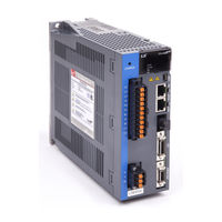
LSIS XDL-L7NHB150U User Manual (348 pages)
EtherCAT AC SERVO DRIVE, XGT SERVO
Brand:
LSIS
| Category:
Controller
| Size: 12 MB
Table of Contents
Table of Contents
8
1 Product Configuration
13
Product Verification
13
Product Specifications
14
Part Names
16
Servo Drive Parts
16
Servo Motor Parts
21
System Configuration Example
22
2 Wiring and Connection
23
Installation of Servo Motor
23
Operating Environment
23
Preventing Impact
23
Motor Connection
23
The Load Device Connection
24
Cable Installation
24
Installation of Servo Drive
25
Installation and Usage Environment
25
Internal Block Diagram of Drive
26
XDL-L7NH Drive Block Diagram (XDL-L7NHB010U~ XDL-L7NHB035U)
26
XDL-L7NH Drive Block Diagram (XDL-L7NHB050U~ XDL-L7NHB075U)
27
XDL-L7NH Drive Block Diagram (XDL-L7NHB150U)
28
Power Supply Wiring
29
Power Supply Wiring Diagram
30
Power Circuit Electrical Components
33
Regenerative Resistor Options
39
Wiring for Input/Output Signals
40
Names and Functions of Digital Input/Output Signals
40
Names and Functions of Analog Input/Output Signals
42
Examples of Connecting Input/Output Signals
44
Examples of Connecting Input/Output Signals
46
Wiring of Encoder Signal (ENCODER)
47
Quadrature Encoder Signaling Unit Wiring
47
Serial Encoder Signaling Unit Wiring
48
Multi-Turn Encoder Signaling Unit Wiring
50
Tamagawa Encoder Signaling Unit Wiring
51
Endat 2.2 Encoder Signaling Unit Wiring
52
Wiring for Safety Function Signals (STO)
53
Names and Functions of Safety Function Signals
53
Example of Connecting Safety Function Signals
54
Bypass Wiring of Safety Function Signal
55
Wiring for Ethercat Communication Signals
56
Names and Functions of Ethercat Communication Signals
56
Example of Drive Connection
57
3 Ethercat Communication
59
Structure of Canopen over Ethercat
59
Ethercat State Machine
60
Status LED
61
Data Type
63
PDO Assignment
63
Synchronization Using the DC (Distributed Clock)
66
Emergency Messages
67
4 Cia402 Drive Profile
69
State Machine
69
Operation Modes
71
Position Control Modes
73
Cyclic Synchronous Position Mode
73
Profile Position Mode
76
Velocity Control Mode
81
Cyclic Synchronous Velocity Mode
81
Profile Velocity Mode
84
Torque Control Modes
87
Cyclic Synchronous Torque Mode
87
Profile Torque Mode
89
Homing
91
Homing Method
92
Touch Probe Function
106
5 Drive Application Functions
109
Drive Front Panel
109
7-Segment for Indicating Servo Status
109
Input/Output Signals Setting
112
Assignment of Digital Input Signals
112
Assignment of Digital Output Signals
114
Use of User I/O
119
Electric Gear Setup
123
Electric Gear
123
Example of Electric Gear Setup
124
Settings Related to Speed Control
125
Smooth Acceleration and Deceleration
125
Servo-Lock Function
126
Signals Related to Speed Control
126
Settings Related to Position Control
127
Position Command Filter
127
Signals Related to Position Control
129
Settings Related to Torque Control
130
Speed Limit Function
130
Positive/Negative Limit Settings
131
Setting the Brake Output Signal Function
132
Torque Limit Function
134
Gain Switching Function
137
Gain Group Switching
137
P/PI Control Switching
139
Dynamic Brake
141
Regenerative Resistance Setting
142
Use of Internal Regenerative Resistor
143
Use of External Regenerative Resistor
145
Other Considerations
146
Configuration of Drive Node Address (ADDR)
147
6 Safety Functions
149
Safe Torque off (STO) Function
149
External Device Monitor (EDM)
152
Example of Using Safety Function
153
How to Verify Safety Function
153
Precautions for Using Safety Function
154
7 Tuning
155
Auto Gain Tuning
155
Manual Gain Tuning
157
Gain Tuning Sequence
157
Vibration Control
159
Notch Filter
159
Adaptive Filter
160
Analog Monitor
162
8 Procedure Function
165
Manual JOG Operation
165
Programmed Jog Operation
166
Deleting Alarm History
167
Auto Gain Tuning
169
Index Pulse Search
169
Absolute Encoder Reset
170
Instantaneous Maximum Torque Initialization
170
Phase Current Offset Tuning
171
Software Reset
172
Commutation
172
9 Object Dictionary
173
General Objects
173
Manufacturer Specific Objects
189
Cia402 Objects
240
10 Product Specifications
261
Servo Motor
261
Product Characteristcs
261
Outline Diagram
279
Servo Drive
289
Product Characteristics
289
Outline Diagram
292
Options and Peripheral Devices
295
11 Maintenance and Inspection
303
Precautions
303
What to Inspect
303
Replacing Parts
304
Diagnosing and Troubleshooting Abnormalities
305
Servo Motor
305
Servo Drive
306
12 Test Drive
318
Preparation for Operation
319
Test Drive Using Twincat System Manager
320
Test Drive Using LSIS PLC (XGT + PN8B)
328
13 Appendix
335
Firmware Update
335
Use of USB OTG
335
Use of Foe (File Access over Ethercat)
337
Use of Drive CM
341
Advertisement
Advertisement
Related Products
LSIS XDL-L7NH Series
LSIS XDL-L7NHB075U
LSIS XDL-L7NHB010U
LSIS XDL-L7NHB035U
LSIS XDL-L7NHB050U
LSIS XDL-L7SA001X
LSIS XDL-L7SA010X
LSIS XDL-L7SA008X
LSIS XDL-L7SA050X
LSIS XDL-L7SA035X
LSIS Categories
Controller
Inverter
Control Unit
DC Drives
Relays
More LSIS Manuals
Login
Sign In
OR
Sign in with Facebook
Sign in with Google
Upload manual
Upload from disk
Upload from URL