
Related Manuals for LSIS XEC-DR32H


Summary of Contents for LSIS XEC-DR32H
- Page 1 Programmable Logic Controller XGB Hardware (IEC) User’s Manual ○○○○○○ Series XGT Series XEC-DR32H XEC-DN32H XEC-DP32H XEC-DR64H XEC-DN64H XEC-DP64H XEC-DR32H/D1 XEC-DR64H/D1...
- Page 2 Safety Instruction Before using the product … For your safety and effective operation, please read the safety instructions thoroughly before using the product. ► Safety Instructions should always be observed in order to prevent accident or risk with the safe and proper use the product. ►...
- Page 3 Safety Instruction Safety Instructions when designing Warning Please, install protection circuit on the exterior of PLC to protect the whole control system from any error in external power or PLC module. Any abnormal output or operation may cause serious problem in safety of the whole system.
- Page 4 Safety Instruction Safety Instructions when designing Caution I/O signal or communication line shall be wired at least 100mm away from a high-voltage cable or power line. If not, it may cause abnormal output or operation. Safety Instructions when designing Caution ...
- Page 5 Safety Instruction Safety Instructions when wiring Warning Prior to wiring, be sure that power of PLC and external power is turned off. If not, electric shock or damage on the product may be caused. Before PLC system is powered on, be sure that all the covers of ...
- Page 6 Safety Instruction Safety Instructions for test-operation or repair Warning Don’t touch the terminal when powered. Electric shock or abnormal operation may occur. Prior to cleaning or tightening the terminal screws, let all the external power off including PLC power. If not, electric shock or abnormal operation may occur.
- Page 7 1. Address & phone number changed Back Cover 2. Add new module Ch2.1, Ch2.2, V1.7 2015.7 Ch2.3.3, Ch2.3.4 3. Vibration Specification modified Ch3.1 The number of User’s manual is indicated the right side of the back cover. ⓒ LSIS Co. ,Ltd. 2009 All Rights Reserved.
- Page 8 About User’s Manual About User’s Manual Thank you for purchasing PLC of LSIS Co.,Ltd. Before use, make sure to carefully read and understand the User’s Manual about the functions, performances, installation and programming of the product you purchased in order for correct use and importantly, let the end user and maintenance administrator to be provided with the User’s Manual.
-
Page 9: Table Of Contents
◎ Contents ◎ Chapter 1 Introduction ..............1-1~1-5 1.1 Guide to Use This Manual ..................1-1 1.2 Features ........................ 1-2 1.3 Terminology ......................1-4 Chapter 2 System Configuration ............2-1~2-11 2.1 XGB System Configuration .................. 2-1 2.2 Product List ......................2-2 2.3 Classification and Type of Product Name ............. - Page 10 4.5 Battery ......................... 4-8 4.5.1 Battery specification ....................4-8 4.5.2 Notice in using ......................4-8 4.5.3 Life of battery ......................4-8 4.5.4 How to change the battery ..................4-9 Chapter 5 Program Configuration and Operation Method ....5-1~5-28 5.1 Program Instruction ....................5-1 5.1.1 Program execution methods ..................
- Page 11 7.1 Introduction ......................7-1 7.2 Digital Input Specifications of Main Unit ..............7-7 7.2.1 XEC-DR32H / XEC-DN32H input unit (Source/Sink type) ......... 7-7 7.2.2 XEC-DR64H / XEC-DN64H input unit (Source/Sink Type) ........7-8 7.3 Digital Output Specification of Main Unit ............... 7-9 7.3.1 XEC-DR32H output unit .....................
- Page 12 7.5.4 16 point transistor output module (Sink type) ............7-21 7.5.5 32 point transistor output module (Sink type) ............7-22 7.5.6 8 point transistor output module (Source type) ............7-23 7.5.7 16 point transistor output module (Source type) ............7-24 7.5.8 32 point transistor output module (Source type) ............
- Page 13 9.3.1 Power wiring ......................9-14 9.3.2 I/O Device wiring ...................... 9-17 9.3.3 Grounding wiring ...................... 9-17 9.3.4 Specifications of wiring cable ................... 9-18 Chapter 10 Maintenance ..............10-1~10-2 10.1 Maintenance and Inspection ................10-1 10.2 Daily Inspection ....................10-1 10.3 Periodic Inspection ................... 10-2 Chapter 11 Troubleshooting ............
- Page 14 Appendix 4 Instruction List ........... App.4-1~App.4-13 Appendix 4.1 Basic Function ................. App.4-1 Appendix 4.2 MK(MASTER-K) Function ............. App.4-10 Appendix 4.3 Array Operation Function ............. App.4-10 Appendix 4.4 Basic Function Block..............App.4-11...
-
Page 15: Chapter 1 Introduction
Chapter 1 Introduction Chapter 1 Introduction 1.1 Guide to Use This Manual This manual includes specifications, functions and handling instructions for the XGB series PLC. This manual is divided up into chapters as follows. Title Contents Describes configuration of this manual, unit’s features and Chapter 1 Introduction terminology. -
Page 16: Features
Chapter 1 Introduction 1.2 Features The features of XGB system are as follows. (1) The system secures the following high performances. (a) High Processing Speed (b) Max. 384 I/O control supporting small & mid-sized system implementation Item Specification Reference Operation processing 83ns / Step speed Max IO contact point... - Page 17 Chapter 1 Introduction (5) Optimized communication environment. (a) With max. 2 channels of built-in COM (excl. loader), up to 2 channel communication is available without any expanded of module. (b) Supporting various protocols to improve the convenience (leaseddedicated, Modbus, user-defined communication) (c) Communication module may be additionally increased by adding modules (up to 2 rackstages such as Cnet, Enet and etc).
-
Page 18: Terminology
Chapter 1 Introduction (11) Built-in PID (a) Supporting max. 16 loops. (b) Setting parameters by using XG5000 and supporting loop status monitoring conveniently with trend monitor. (c) Control constant setting through the improved automatic Auto-tuning function. (d) With many other additional functions including PWM output, ∆MV, ∆PV and SV Ramp, improving the control preciseness. - Page 19 Chapter 1 Introduction Terms Definition Remark Current flows from the switch to the PLC input terminal if a input signal turns on. Z: Input Sink Input impedance − Current flows from the PLC input terminal to the switch after a input signal turns on.
-
Page 20: Chapter 2 System Configuration
Chapter 2 System Configuration Chapter 2 System Configuration The XGB series has suitable to configuration of the basic, computer link and network systems. This chapter describes the configuration and features of each system. 2.1 XGB System Configuration XGB series System Configuration is as follows. Expanded I/O module and special module are available to connect maximum 7 stages for “S”... -
Page 21: Product List
XGB series’ product list is as follows. Types Model Description Remark XEC-DR32H AC 100V~220V power, DC24V input 16 points, relay output 16 points XEC-DN32H AC 100V~220V power, DC24V input 16 points, TR output 16 points XEC-DN32H/DC DC 24V power, DC24V input 16 points, TR output 16 points... - Page 22 Chapter 2 System Configuration Types Model Description Remark XBL-C21A Cnet (RS-232C/Modem) I/F XBL-C41A Cnet (RS-422/485) I/F XBL-EMTA Enet I/F XBL-EIMT RAPIEnet I/F 2 UTP cable XBL-EIPT EtherNet I/P Module XBL-CMEA CANopen MasterI/F XBL-CSEA CANopen Slave I/F XBL-PMEC Pnet I/F Option XBO-M1024A Memory module module...
-
Page 23: Classification And Type Of Product Name
16 point DC24V XBC-DR64H/DC 32 point 32 point None XBC-DN64H/DC 32 point None 32 point 16 point 16 point None XEC-DR32H 16 point None 16 point XEC-DN32H 32 point 32 point None XEC-DR64H AC110V~220V Compact type 32 point None 32 point... -
Page 24: Classification And Type Of Expansion Module
Chapter 2 System Configuration 2.3.2 Classification and type of expansion module Name of expansion module is classified as follows. No. of IO point XGB series I/O expansion module Relay output(RY) Transistor output (TN/TP) Digital input (DC) Digital input+ sink type transistor output (DN) Digital input+ source type transistor output (DP) Digital input + relay output (DR) Name... -
Page 25: Classification And Type Of Special Module
Chapter 2 System Configuration 2.3.3 Classification and type of special module Special module is classified as follows Non-insulation type (A) Insulation type (S) XGB series No. of IO point Expansion special module Analog input (AD) Analog voltage output (DC) Analog current output (DV) Analog combined module (AH) RTD input (RD) Thermocouple input (TC) -
Page 26: Classification And Type Of Communication Module
Chapter 2 System Configuration 2.3.4 Classification and type of communication module Name of communication module is classified as follows. C21A Cnet 1 channel (RS-232C): C21A XGB series Cnet 1 channel (RS-422/485): C41A FEnet 1 channel: EMTA RAPIEnet 1 channel: EIMT Expansion communication module Classification Name... -
Page 27: System Configuration
(1) 1:1 communication system (a) 1:1 communication of an external device (computer) with main unit using a built-in port (RS-232C/RS-485) XEC-DR32H RS-232C / RS-485 (b) 1:1 communication with main unit using a built-in RS-485 port (In case of built-in RS-232C,it is for connecting to HMI device.) - Page 28 Chapter 2 System Configuration (c) 1:1 RS-232C Communication with remote device via modem by Cnet I/F modules XEC-DR32H XBL-C21A XBL-C21A XEC-DR32H Modem Modem XEC-DR32H XBL-C21A Modem Modem (d) 1:1 communication of an external device (monitoring unit) with main unit using a built-in RS- 232C/485 port.
- Page 29 Chapter 2 System Configuration (2) 1:n Communication system (a) Using RS-485 built-in function can connect between one computer and multiple main units for up to 32 stations. XEC-DN32H XEC-DN32H PADT connection Max. 32 stations available Max. 32 stations available Built-in RS-232C connection (b) Using RS-485 built-in function/expansion Cnet I/F module can be connect for up to 32 stations.
-
Page 30: Ethernet System
Chapter 2 System Configuration 2.4.2 Ethernet system Ethernet made by cooperation of Xerox, Intel, DEC is standard LAN connection method (IEEE802.3), which is network connection system using 1.5KB packet with 100Mbps transmission ability. Since Ethernet can combine a variety of computer by network, it is called as standard specification of LAN and diverse products. -
Page 31: Chapter 3 General Specifications
• Peak acceleration: 147 m/s (15G) Shock • Duration: 11ms resistance • Half-sine, 3 times each direction per each axis AC: ±1,500 V Square wave LSIS standard DC: ±900 V Impulse noise Electrostatic IEC61131-2 4kV (Contact discharge) discharge IEC61000-4-2 Radiated... -
Page 32: Chapter 4 Cpu Specifications
Chapter 4 CPU Specifications Chapter 4 CPU Specifications 4.1 Performance Specifications The following table shows the general specifications of the XGB main module type Specifications Items Remark XEC- XEC- XEC- XEC- XEC- XEC- DR32H(/D1) DR64H(/D1) DN32H(/DC) DN64H DP32H DP64H Operator Numb Basic function 136 + Real number operation function... - Page 33 Chapter 4 CPU Specifications Items Specifications Remark Controlled by instructions, Auto-tuning, PWM output, Manual output, Adjustable operation scan time, Anti Windup, Delta MV function, SV- PID control function Ramp function Dedicated protocol support MODBUS protocol support RS-232C 1 port Cnet I/F function User defined protocol support RS-485 1 port 1 phase: 100 kHz 4 channel, 20kHz 4 channel...
-
Page 34: Names Of Part And Function
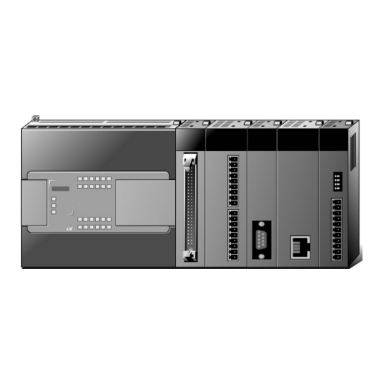
Chapter 4 CPU Specifications 4.2 Names of Part and Function XGB Compact type main unit (IEC language) ③ ① ⑩ ⑤ ⑦ ② ⑨ ⑥ ④ Name Description ① ▪ Input indicator LED Input indicator LED ▪ PADT connecting PADT connecting USB (USB 1.1 supported) 1 channel, ②... -
Page 35: Power Supply Specifications
Chapter 4 CPU Specifications 4.3 Power Supply Specifications Describes power specification of main unit Specification XEC-DR32H XEC-DR64H Items XEC- XEC- XEC- XEC-DN32H XEC-DN64H DN32H/DC DR32H/D1 DR64H/D1 XEC-DP32H XEC-DP64H Rated voltage AC 100 ~ 240 V DC24V DC 12/24V (UL warranty voltage) DC19.2~28.8V... - Page 36 Chapter 4 CPU Specifications (1) Consumption current (DC 5V) (Unit : ㎃) Consumption current Type Model XEC-DR32H XEC-DR64H 1,040 XEC-DN32H XEC-DN64H Main unit XEC-DP32H XEC-DP64H XEC-DR32H/D1 XEC-DR64H/D1 1,040 XBE-DC32A XBE-DC16A/B XBE-DC08A XBE-RY16A XBE-RY08A/B XBE-TN32A Expansion I/O module XBE-TN16A XBE-TN08A XBE-TP32A...
-
Page 37: Calculation Example Of Consumption Current/Voltage
(2) XGB PLC configuration example 2 Internal 5V consumption Type Model Unit No. Remark current (Unit : ㎃) Main unit XEC-DR32H In case all contact points are On. XBE-DR16A (Maximum consumption current) XBE-TN32A Expansion module XBF-AD04A All channel is used. (Maximum consumption current) - Page 38 Chapter 4 CPU Specifications (3) XGB PLC configuration example 3 Internal 5V consumption Type Model Unit No. Remark current (Unit : ㎃) Main unit XEC-DR64H 1,040 In case of all contact points are XBE-DR16A (Maximum consumption current) XBE-TN32A Expansion module XBF-AD04A All channel is used.
-
Page 39: Battery
Chapter 4 CPU Specifications 4.5 Battery Battery is inserted in XGB PLC compact main unit (XEC-DR32/64H, XEC-DN32/64H, XEC-DP32/64H) 4.5.1 Battery specification Item Specification Voltage/Current DC 3V / 220 mAh Warranty period 3 years (ambient temp.) Program and data backup, Purpose RTC operation in case of power failure Specification Manganese Dioxide lithium battery... -
Page 40: How To Change The Battery
Chapter 4 CPU Specifications 4.5.4 How to change the battery The user should change the battery used to save the program and backup the data in case of power failure periodically. Though the user eliminate the battery, it works for 30 minute by super capacitor. Change the battery as fast as possible. -
Page 41: Chapter 5 Program Configuration And Operation Method
Chapter 5 Program Configuration and Operation Method Chapter 5 Program Configuration and Operation Method 5.1 Program Instruction 5.1.1 Program execution methods (1) Cyclic operation method (Scan) This is a basic program proceeding method of PLC that performs the operation repeatedly for the prepared program from the beginning to the last step, which is called ‘program scan’. -
Page 42: Operation Processing During Momentary Power Failure
Chapter 5 Program Configuration and Operation Method (2) Interrupt operation (Cycle time, Internal device) This is the method that stops the program operation in proceeding temporarily and carries out the operation processing which corresponds to interrupt program immediately in case that there occurs the status to process emergently during PLC program execution. -
Page 43: Scan Time
Chapter 5 Program Configuration and Operation Method 5.1.3 Scan time The processing time from program step 0 to the next step 0 is called ‘Scan Time’. (1) Scan time calculation expression Scan time is the sum of the processing time of scan program and interrupt program prepared by the user and PLC internal time, and is distinguished by the following formula. -
Page 44: Scan Watchdog Timer
Chapter 5 Program Configuration and Operation Method 5.1.4 Scan Watchdog timer WDT (Watchdog Timer) is the function to detect the program congestion by the error of hardware and software of PLC CPU module. (1) WDT is the timer used to detect the operation delay by user program error. The detection time of WDT is set in Basic parameter of XG5000. -
Page 45: Program Execution
Chapter 5 Program Configuration and Operation Method 5.2 Program Execution 5.2.1 Configuration of program All functional elements need to execute a certain control process are called as a ‘program’. Program is stored in the built-in RAM mounted on a CPU module or flash memory of a external memory module. The following table shows the classification of the program. - Page 46 Chapter 5 Program Configuration and Operation Method (1) Scan program (a) Function • This program performs the operation repeatedly from 0 step to last step in order prepared by the program to process the signal that is repeatedly regularly every scan. •...
-
Page 47: Interrupt
Chapter 5 Program Configuration and Operation Method 5.2.3 Interrupt For your understanding of Interrupt function, here describes program setting method of XG5000 which is an XGB programming S/W. Example of interrupt setting is as shown bellows. • Interrupt setting Interrupt source Interrupt name priority Task No. - Page 48 Chapter 5 Program Configuration and Operation Method (1) How to prepare interrupt program Generate the task in the project window of XG5000 as below and add the program to be performed by each task. For further information, please refer to XG5000 user’s manual. (It can be additional when XG5000 is not connected with PLC.) (a) Click right button of mouse on project name and click 『Add item』-『Task』.
- Page 49 Chapter 5 Program Configuration and Operation Method (c) Click right button of mouse at registered task and select『Add Item』-『Program』. (d) Make initializing program. In initializing program, INIT_DONE instruction must be made. If not, Scan program is not executed. 5- 9...
- Page 50 Chapter 5 Program Configuration and Operation Method (2) How to prepare Cycle interrupt program Generate the task in the project window of XG5000 as below and add the program to be performed by each task. For further information, please refer to XG5000 user’s manual. (It can be additional when XG5000 is not connected with PLC) (a) Click right button of mouse at registered task and select『Add Item』-『Task』.
- Page 51 Chapter 5 Program Configuration and Operation Method (b) Task type Classification Description Remark Character, number Task name Make Task name. available “2” is the highest Priority Set the priority of task. (2~7) priority number. Set the Task number. • Cycle time task (0 ~ 7): 8 Task number •...
- Page 52 Chapter 5 Program Configuration and Operation Method (d) Register the Program name and Program description. (e) It is displayed the program window to write task program. (f) It is displayed the setting in project window. 5- 12...
- Page 53 Chapter 5 Program Configuration and Operation Method (3) Task type Task type and function is as follows. Type Cycle time task I/O task Internal device task Spec. (Interval task) (Interrupt task) (Single task) Max. Task number Cyclic Rising or falling edge of (setting up to max.
- Page 54 Chapter 5 Program Configuration and Operation Method (e) Protection of Program in execution from Task Program 1) In case that the continuity of program execution is interrupted by high priority Task Program during program execution, it is available to prohibit the execution of Task Program partially for the part in problem.
- Page 55 Chapter 5 Program Configuration and Operation Method 3) When setting the execution cycle of cyclic task program, consider the possibility that the demand to execute several cyclic task program at the same time occurs. If 4 cyclic task programs that the cycle is 2sec, 4sec, 10sec and 20sec are used, 4 demands of execution per 20 seconds shall be occurred at the same time and scan time may extend instantaneously.
- Page 56 Chapter 5 Program Configuration and Operation Method (a) Items to be set in Task Set the execution condition and priority to the task being executed. Check the task no. to manage the task. (b) I/O task processing If interrupt signal from external signal (I/O) is occurred on main unit (%IX0.0.0~%IX0.0.7), task program is executed by external (I/O) signal.
- Page 57 Chapter 5 Program Configuration and Operation Method (c) Precautions in using internal device task program 1) Accordingly, even if the execution condition of internal device task program occurs in Scan Program or Task Program (Cycle time, I/O), it shall not be executed immediately but executed at the time of completion of Scan Program.
- Page 58 Chapter 5 Program Configuration and Operation Method Scan started Scan program stopped New scan started (Initial operation started) PO executed P1 executed 10ms_Cycle time Program 2 Internal device_%MX0 Program 3 External I/O_%IX0.0.0 Time 6 7 8 10 12 20 22 24 25 30 32 34 Process per time Time (㎳)
-
Page 59: Operation Mode
Chapter 5 Program Configuration and Operation Method 5.3 Operation Mode For operation mode of CPU module, there are 3 types such as RUN mode, STOP mode and DEBUG mode.. Here describes the operation processing of each operation mode. 5.3.1 RUN mode This is the mode to executed program operation normally. -
Page 60: Stop Mode
Chapter 5 Program Configuration and Operation Method 5.3.2 STOP mode This is the mode in stop state without Program operation. It is available to transmit the program through XG5000 only in Remote STOP mode. (1) Processing at Mode Change Clear the output image area and execute output refresh. (2) Operation Processing Contents (a) Executes I/O refresh. - Page 61 Chapter 5 Program Configuration and Operation Method Item Description Remark Change the debug ↔ stop mode Start/Stop Debugging It starts debug operation. Step Over It operates by 1 step. Other Step Into It starts the subroutine program. operation is identical to Step Out It finished the subroutine program.
- Page 62 Chapter 5 Program Configuration and Operation Method (c) Step Over ▪ Run the program to next step. At break point, Step over indicator is displayed. error 1 error 2 (d) Breakpoint List ▪ It displays current Breakpoint List. It supports Select All, Reset All, Goto, Remove, Remove All. 5- 22...
- Page 63 Chapter 5 Program Configuration and Operation Method (e) Break condition ▪ It sets Device Break and Scan Break. Remark 1) Refer to XG5000 Users Manual ‘Chapter 12 Debugging’ for detailed information. 5- 23...
-
Page 64: Change Operation Mode
Chapter 5 Program Configuration and Operation Method 5.3.4 Change operation mode (1) Operation Mode Change Method The method to change operation mode are as follows. (a) By mode key of CPU module (b) By connecting the programming tool (XG5000) to communication port of CPU (c) By changing the operation mode of other CPU module connected to network by XG5000 connected to communication port of CPU. -
Page 65: Memory
Chapter 5 Program Configuration and Operation Method 5.4 Memory There are two types of memory in CPU module that the user can use. One is Program Memory that saves the user program written by the user to build the system, and the other is Data Memory that provides the device area to save the data during operation. -
Page 66: Data Memory
Chapter 5 Program Configuration and Operation Method 5.4.2 Data memory Contents and size of data memory are as follows. Item Size Data memory entire area 256 KB System area : I/O information table 143 KB Forced I/O table ... - Page 67 Chapter 5 Program Configuration and Operation Method 1) Initialization of data according to restart mode There are three variable related with restart mode (Default, initialization and retain variable). Initialization method about each variable in case of executing restart mode is as follows. Mode COLD WARM...
-
Page 68: Data Memory Map
Chapter 5 Program Configuration and Operation Method 5.4.4 Data Memory Map Data area User program area Z000 Automatic variable Parameter area (32 KB) Z127 User program area %IX0.0.0 Input variable (200 KB) (2 KB) %IX15.15.63 “I” %QX0.0.0 Output variable (2 KB) %QX15.15.63 “Q”... -
Page 69: Chapter 6 Cpu Functions
Chapter 6 CPU Functions Chapter 6 CPU Functions 6.1 Type Setting It describes setting of XGB PLC type. CPU type Language Description Reference Series XGB-DR16C3 Dedicated product Module type language “S” type : XBM-DN16/32S , XBM- XGB-XBMS Module type language DR16S “H”... -
Page 70: Parameter Setting
Chapter 6 CPU Functions 6.2 Parameter Setting This paragraph describes how to set parameters. 6.2.1 Basic parameter setting Clicking Basic Parameter in the project window shows the following window. There are three main options ; “Basic Operation Setup” , “Device Area Setup” and “Error Operation Setup”. -
Page 71: I/O Parameter Setting
Chapter 6 CPU Functions 6.2.2 I/O parameter setting This setting is to set and reserve each I/O information. Clicking 『I/O Parameter』 in the project window shows the following setting window. Clicking 『Module』 in 『Slot Position』 indicates a list of modules, in which you may set I/O corresponding to the actual system. -
Page 72: Self-Diagnosis Function
Chapter 6 CPU Functions 6.3 Self-diagnosis Function 6.3.1 Saving of error log CPU module logs errors occurred so that the causes will be identified and fixed easily. Clicking 『Error/Warning』 of 『Online』 shows the current error and previous error log. Item Description Remarks Error/Warning... - Page 73 Chapter 6 CPU Functions (2) Operation mode if trouble occurs PLC system logs any trouble occurred in flag and determines whether to stop or resume operation depending on trouble mode. (a) PLC hardware trouble In case an error occurs so that PLC such as CPU module and power module may not work normally, the system is halted, but any warning may not interfere with the operation.
-
Page 74: Remote Functions
Chapter 6 CPU Functions 6.4 Remote Functions CPU module may change operation by communication as well as by key switches mounted on the module. To operate it remotely, it is necessary to set ‘RUN/STOP’ switch to ‘STOP’. (1) Remote operations are as follows. (a) Operable by accessing to XG5000 through RS-232C port mounted on CPU module. -
Page 75: Forced Input/Output On And Off Function
Chapter 6 CPU Functions 6.5 Forced Input/Output On and Off Function Force I/O function is used to force to turn I/O areas on or off, regardless of program results. 6.5.1 Force I/O setup Click『 Online 』-『 Force I/O 』. Item Description Move address Select base and slot... - Page 76 Chapter 6 CPU Functions 6.5.2 Processing time and processing method of Force Input/Output On and Off (1) Forced Input Regarding input, at the time of input refresh it replaces the data of contact set as Force On/Off among data read from input module with the data as Force and updates input image area. Therefore, user program executes operations with actual input data while Force input area is operated with data set as Force.
-
Page 77: Direct Input/Output Operation
Chapter 6 CPU Functions 6.6 Direct Input/Output Operation Refreshing I/O operates after completion of scan program. If data of I/O is changed while program is scanned, it does not refreshed at the changed moment. Refreshed I/O data is applied after ‘END’ instruction on program. -
Page 78: Diagnosis Of External Device
Chapter 6 CPU Functions 6.7 Diagnosis of External Device This flag is provided for a user to diagnose any fault of external device and, in turn, execute halt or warning of the system. Use of this flag displays faults of external device without any complicated program prepared and monitors fault location without any specific device (XG5000 and etc) or source program. -
Page 79: Allocation Of Input/Output Number
Chapter 6 CPU Functions 6.8 Allocation of Input/Output Number Allocation of I/O number is to allocate an address to every I/O of each module to read data from input module and output data to output module when it executes operations. XGB series adopts each I/O 64 points occupation to every module. - Page 80 Chapter 6 CPU Functions In case of using monitor function of XG5000, I/O allocation information is displayed. contact point allocation information Description of each module 6- 12...
-
Page 81: Online Editing
Chapter 6 CPU Functions 6.9 Online Editing It is possible to modify program and communication parameter during operation of PLC without control operation stopped. The following describes basic modification. For details of modifying program, refer to XG5000 Users Manual. Items to be modified during operation are as follows. •... - Page 82 Chapter 6 CPU Functions (3) If you modify program, background color changes to indicates start of online editing. (4) Upon the modification of program, click 『Online』-『Write Modified Program』. 6- 14...
- Page 83 Chapter 6 CPU Functions (5) Upon the writing of program, click 『Online』-『End Online Editing』. (6) The program background returns and the program modification during run is completed. Remark ▪ For parameter modification during run, change each parameter on XG-PD and click『Online』-『Write Modified Program 』.
-
Page 84: Reading Input/Output Information
Chapter 6 CPU Functions 6.10 Reading Input/Output Information It monitors information of individual modules consisted of XGB series system. (1) Click『Online』-『I/O Info』. Then, information of each module connected to the system is monitored. (2) If clicking Details after selecting a module, it displays detail information of a selected module. 6- 16... -
Page 85: Monitoring
Chapter 6 CPU Functions 6.11 Monitoring It monitors system information of XGB series system. (1) Clicking『Monitor』 displays the following sub-menus. (2) Items and descriptions Item Description Remarks Start/Stop Monitoring Designate the start and stop of monitor. Click for reverse turn. Pause Pause monitoring. - Page 86 Chapter 6 CPU Functions (a) Change current value It changes the current value of each device selected in the current program window. (b) Device monitoring It monitors by device (type). 6- 18...
- Page 87 Chapter 6 CPU Functions (c) Pausing conditions It stops monitoring in case a device value set in the program corresponds. (d) Trend monitoring It displays device values graphically. 6- 19...
- Page 88 Chapter 6 CPU Functions (e) Custom events 1) It monitors detail information when an event set by a user occurs. Additional user event may be registered. 2) It sets basic setting and relative device. If rising edge of %MX0 device occurs, it records the message of an alarm, “Out of order Water Tank 1” and the device values of DATA (%MW0), %MW100, tog_4s device are recorded.
- Page 89 Chapter 6 CPU Functions 4) Monitor event history of custom event. 5) Double-clicking a number produced monitors the relative values of device and the detail message as follows. Remark ▪For details of monitor, refer to XG5000 Users Manual. 6- 21...
-
Page 90: Rtc Function
Chapter 6 CPU Functions 6.12 RTC function XGB PLC supports the RTC (clock) function and user can use this function for time management of system or error log. RTC function is executed steadily when power is off or instantaneous power cut status. - Page 91 Chapter 6 CPU Functions (c) Modification of clock data by program You can set clock data by program. It is used when you make system to set clock manually by external Digit switch or modify clock periodically through network. ‘RTC-SET’ function block is used to write the clock data to a clock. If you input the clock data and execute the function block, it writes the clock data to a clock at the scan end.
- Page 92 Chapter 6 CPU Functions 6.13 External Memory Module You can save user program safely or download user program to PLC without special handling when user program is damaged by using external memory module in XGB PLC 6.13.1 Structure RUN LED WRITE LED READ LED 0 : READ mode...
-
Page 93: Chapter 7 Input/Output Specifications
Chapter 7 Input/Output Specifications Chapter 7 Input/Output Specifications 7.1 Introduction Here describes the notices when selecting digital I/O module used for XGB series. (1) For the type of digital input, there are two types such as current sink input and current source input. - Page 94 Chapter 7 Input/Output Specifications (7) Relay life of Relay output module is shown as below. Max. life of Relay used in Relay output module is shown as below. AC 125V Resistive load DC 30V Resistive load AC 250V Resistive load Open/Close current (A)
- Page 95 Chapter 7 Input/Output Specifications (8) A clamped terminal with sleeve can not be used for the XGB terminal strip. The clamped terminals suitable for terminal strip are as follows (JOR 1.25-3:Daedong Electricity in Korea). 6.0mm or less 6.0mm or less (9) The cable size connected to a terminal strip should be 0.3~0.75 ㎟...
- Page 96 Chapter 7 Input/Output Specifications (a) Setting input filter 1) Click I/O Parameter』in the project window of XG5000 2) Click『Module』 at the slot location.
- Page 97 Chapter 7 Input/Output Specifications 3) Set I/O module really equipped. 4) After setting I/O module, click Input Filter. 5) Set filter value.
- Page 98 Chapter 7 Input/Output Specifications (b) Setting output status in case of error 1) Click Emergency Out in the I/O parameter setting window. 2) Click Emergency Output. If it is selected as Clear, the output will be Off and if Hold is selected, the output will be kept.
-
Page 99: Digital Input Specifications Of Main Unit
Chapter 7 Input/Output Specifications 7.2 Digital Input Specifications of Main Unit 7.2.1 XEC-DR32H / XEC-DN32H input unit (Source/Sink type) Model Main unit XEC-DN32H(/DC) Specification XEC-DR32H XEC-DR32H/D1 XEC-DP32H Input point 16 point Insulation method Photo coupler insulation Rated input voltage DC24V... -
Page 100: Xec-Dr64H / Xec-Dn64H Input Unit (Source/Sink Type)
Chapter 7 Input/Output Specifications TB24 7.2.2 XEC-DR64H / XEC-DN64H input unit (Source/Sink Type) Model Main unit XEC-DN64H XEC-DR64H XEC-DR64H/D1 Specification Input point 32 point Insulation method Photo coupler insulation Rated input voltage DC24V DC 12/24V About 5/10 ㎃ About 4 ㎃ (point 0~7: About 10 ㎃) Rated input current (point 0~7: About 7/15 ㎃) DC 9.5~30V... -
Page 101: Digital Output Specification Of Main Unit
Chapter 7 Input/Output Specifications TB42 7.3 Digital Output Specification of Main Unit 7.3.1 XEC-DR32H output unit Model Main unit XEC-DR32H Specification Output point 16 point Insulation method Relay insulation Rated load DC24V 2A (Resistive load) / AC220V 2A (COSΦ = 1), 5A/COM voltage/current Min. -
Page 102: Xec-Dr64H Output Unit
Chapter 7 Input/Output Specifications TB24 COM3 7.3.2 XEC-DR64H output unit Model Main unit Specification XEC-DR64H Output point 32 point Insulation method Relay insulation Rated load DC24V 2A (resistive load) / AC220V 2A (COSΦ = 1), 5A/COM voltage/current Min. load DC5V / 1 ㎃ voltage/current Max. -
Page 103: Xec-Dn32H Output Unit (Sink Type)
Chapter 7 Input/Output Specifications 7.3.3 XEC-DN32H output unit (Sink type) Model Main unit Specification XEC-DN32H(/DC) Output point 16 point Insulation method Photo coupler insulation Rated load voltage DC 12 / 24V Range of load voltage DC 10.2 ~ 26.4V General output : 0.5A / 1 point Max. - Page 104 Chapter 7 Input/Output Specifications 7-12...
-
Page 105: Xec-Dp32H Output Unit (Source Type)
Chapter 7 Input/Output Specifications 7.3.4 XEC-DP32H output unit (Source type) Model Main unit Specification XEC-DP32H Output point 16 point Insulation method Photo coupler insulation Rated load voltage DC 12 / 24V Range of load voltage DC 10.2 ~ 26.4V General output: 0.5A/1 point, Max. -
Page 106: Xec-Dn64H Output Unit (Sink Type)
Chapter 7 Input/Output Specifications 7.3.5 XEC-DN64H output unit (Sink type) Model Main unit Specification XEC-DN64H 32 point Output point Photo coupler insulation Insulation method Rated load DC 12 / 24V voltage Load voltage range DC 10.2 ~ 26.4V General output : 0.5A / 1 point Max. -
Page 107: Xec-Dp64H Output Unit (Source Type)
Chapter 7 Input/Output Specifications 7.3.6 XEC-DP64H Output unit (Source type) Model Main unit Specification XEC-DP64H point Output point Photo coupler insulation Insulation method Rated load DC 12 / 24V voltage Load voltage range DC 10.2 ~ 26.4V General output: 0.5A/1 point, Max. -
Page 108: Digital Input Module Specification
Chapter 7 Input/Output Specifications 7.4 Digital Input Module Specification 7.4.1 8 point DC24V input module (Source/Sink type) Model DC input module XBE-DC08A Specification Input point 8 point Insulation method Photo coupler insulation Rated input voltage DC24V About 4 ㎃ Rated input current Operation voltage range DC20.4~28.8V (ripple rate <... -
Page 109: Point Dc24V Input Module (Sink/Source Type)
Chapter 7 Input/Output Specifications 7.4.2 16 point DC24V input module (Sink/Source type) Model DC input module XBE-DC16A XBE-DC16B Specification Input point 16 point Insulation method Photo coupler insulation Rated input voltage DC24V DC 12/24V About 4 ㎃ Rated input current About 4/8mA DC20.4~28.8V DC 9.5V~30V... -
Page 110: Point Dc24V Input Module (Source/Sink Type)
Chapter 7 Input/Output Specifications 7.4.3 32 point DC24V input module (Source/Sink type) Model DC input module XBE-DC32A Specification Input point 32 point Insulation method Photo coupler insulation Rated input voltage DC24V About 4 ㎃ Rated input current Operation voltage range DC20.4~28.8V (ripple rate <... -
Page 111: Digital Output Module Specifications
Chapter 7 Input/Output Specifications 7.5 Digital Output Module Specification 7.5.1 8 point relay output module Model Relay output module XBE-RY08A Specification Output point 8 point Insulation method Relay insulation Rated load voltage / Current DC24V 2A (Resistive load) / AC220V 2A (COSΨ = 1), 5A/COM DC5V / 1 ㎃... - Page 112 Chapter 7 Input/Output Specifications 7.5.2 16 point relay output module Model Relay output module XBE-RY16A Specification Output point 16 point Insulation method Relay insulation Rated load voltage/ current DC24V 2A (Resistive load) / AC220V 2A (COSΨ = 1), 5A/COM DC5V / 1 ㎃ Min.
-
Page 113: Point Transistor Output Module (Sink Type)
Chapter 7 Input/Output Specifications 7.5.3 8 point transistor output module (Sink type) Model Transistor output module XBE-TN08A Specification Output point 8 point Insulation method Photo coupler insulation Rated load voltage DC 12 / 24V Load voltage range DC 10.2 ~ 26.4V Max. -
Page 114: Point Transistor Output Module (Sink Type)
Chapter 7 Input/Output Specifications 7.5.4 16 point transistor output module (Sink type) Model Transistor output module XBE-TN16A Specification Output point 16 point Insulation method Photo coupler insulation Rated load voltage DC 12 / 24V Load voltage range DC 10.2 ~ 26.4V Max. -
Page 115: Point Transistor Output Module (Sink Type)
Chapter 7 Input/Output Specifications 7.5.5 32 point transistor output module (Sink type) Model Transistor output module XBE-TN32A Specification Output point 32 point Insulation method Photo coupler insulation Rated load voltage DC 12 / 24V Load voltage range DC 10.2 ~ 26.4V Max. -
Page 116: Point Transistor Output Module (Source Type)
Chapter 7 Input/Output Specifications 7.5.6 8 point transistor output module (Source type) Model Transistor output module XBE-TP08A Specification Output point 8 point Insulation method Photo coupler insulation Rated load voltage DC 12 / 24V Load voltage range DC 10.2 ~ 26.4V Max. -
Page 117: Point Transistor Output Module (Source Type)
Chapter 7 Input/Output Specifications 7.5.7 16 point transistor output module (Source type) Model Transistor output module XBE-TP16A Specification Output point 16 point Insulation method Photo coupler insulation Rated load voltage DC 12 / 24V Load voltage range DC 10.2 ~ 26.4V Max. -
Page 118: Point Transistor Output Module (Source Type)
Chapter 7 Input/Output Specifications 7.5.8 32 point transistor output module (Source type) Model Transistor output module XBE-TP32A Specification Output point 32 point Insulation method Photo coupler insulation Rated load voltage DC 12 / 24V Load voltage range DC 10.2 ~ 26.4V Max. -
Page 119: Combined Module Digital Input Specification
Chapter 7 Input/Output Specifications 7.6 Combined Module Digital Input Specification 7.6.1 8 point DC24V input part (Source/Sink type) Model DC input module XBE-DR16A Specification Input Point 8 point Insulation method Photo coupler insulation Rated input voltage DC24V About 4 ㎃ Rated input current Used voltage range DC20.4~28.8V (Within ripple rate 5%) -
Page 120: Combined Module Digital Output Specification
Chapter 7 Input/Output Specifications 7.7 Combined Module Digital Output Specification 7.7.1 8 point relay output part Model Relay output module XBE-DR16A Specification Output point 8 point Insulation method Relay insulation DC24V 2A(resistive load 하) / AC220V 2A(COSΨ = 1), 5A/COM Rated load voltage/current DC5V / 1 ㎃... -
Page 121: Io Wiring By Using Smart Link Board
Chapter 7 Input/Output Specifications 7.8 IO Wiring by Using Smart Link Board 7.8.1 Smart link board Easy wiring is available by connecting the IO connector with smart link board. The available smart link and IO cable are as follows. Smart link Connection cable The no. - Page 122 Chapter 7 Input/Output Specifications 2) Wiring of SLT-T40P and XGB extension modulet Wiring of XGB extension module through SLP-T40P and SLT-CT101-XBE is as follows. At this time, relationship of XGB IO signal and Smart link board terminal number is as follows. The following figure describes signal allocation when SLT-CT101-XBE is used as connection cable.
- Page 123 Chapter 7 Input/Output Specifications 3) I/O wiring - XBE-DC32A (SLP-T40P) Contact No. - XBE-TN32A (SLP-T40P) Contact No. - XBE-TP32A (SLP-T40P) Contact No. 7-31...
- Page 124 Chapter 7 Input/Output Specifications - XBE-TN32A (SLP-RY4A) 7-32...
-
Page 125: High-Speed Counter Specifications
Chapter 8 Built-in High-speed Counter Function Chapter 8 Built-in High-speed Counter Function XGB series have built-in function of High-speed counter in main unit. This chapter describes specifications and usage of High-speed counter’s function. 8.1 High-speed Counter Specifications It describes specifications, setting and usage of function, programming and wiring with external device of built-in main unit. -
Page 126: Designation Of Parts
Chapter 8 Built-in High-speed Counter Function ※1 : XEC-DR32(64)H/D1 unit supports 1-phase 10kpps, 2-phase 5kpps. (2) Counter/Preset input specification Spcification XEC-DR32H/DR64H Classification XEC-DR32H/D1 XEC-DN32H(/DC)/DN64H XEC-DR64H/D1 XEC-DP32H/DP64H 24V DC (20.4V ~ 28.8V) 12V DC (9.5~30V) Input voltage Input current 4㎃ 4㎃... - Page 127 Chapter 8 Built-in High-speed Counter Function (2) Interface with external devices The following table shows list of interface with external device. Signal On/Off Terminal Internal circuit guaranteed 1-phase 2-phase ※2 voltage 20.4~28.8V Ch 0 Ch 0 IX0.0.0 2.7 kΩ Pulse input A-phase input 6V or less Ch 1...
-
Page 128: Counter Function
Chapter 8 Built-in High-speed Counter Function 8.1.3 Counter Function (1) Counter mode (a) High Speed counter module can count High Speed pulses which can not be processed by CPU module’s counter Function Block (CTU, CTD, CTUD, etc.), up to binary value of 32 bits (- 2,147,483,648 ~ 2,147,483,647). - Page 129 Chapter 8 Built-in High-speed Counter Function ● Operation example A-phase input pulse B-phase input pulse Count value 7 Decreasing Increasing Increasing 2) 2-phase count mode a) 2-phase 4-multiplication operation mode A-phase input pulse and B-phase input pulse count at rising/falling respectively. If A-phase input is antecedent to B-phase input, increasing operation starts, and if B-phase input is antecedent to A-phase input, decreasing operation starts.
- Page 130 Chapter 8 Built-in High-speed Counter Function (2) Counter mode 2 types of count (Linear counter, Ring counter) can be selected for the applicable use based on functions. ▪ Counter mode is saved at the following special K area. Area per each channel (word) Mode Ref.
- Page 131 Chapter 8 Built-in High-speed Counter Function +2,147,483,647 Decreasing Increasing -2,147,483,648 Count start point Borrow Carry (b) Ring count Set Ring Counter Min. Value and Max. value. Preset value and compared set value should be in range of ring counter min. value and max. value. •...
- Page 132 Chapter 8 Built-in High-speed Counter Function ▪ Range of Ring counter: user defined min. value ~ user defined max. value ▪ Counter display: in case of using ring counter, user defined max. value is not displayed. 1) During increasing count ■...
- Page 133 Chapter 8 Built-in High-speed Counter Function Carry occurred 2,147,483,647 Carry occurred Ring Count maximum value Present position Ring Count minimum value ○: Not included ●: Included Present position -2,147,483,648 ※ ※ If out of the user-defined If within the user-defined range range 4) Operation when setting Ring Count based on present count value (during decreasing count)
- Page 134 Chapter 8 Built-in High-speed Counter Function (3) Compared output (a) High Speed counter module has a compared output function used to compare present count value with compared value in size to output as compared. (b) Available compared outputs are 2 for 1 channel, which can be used separately. (c) Compared output conditions are 7 associated with >, =, <...
- Page 135 Chapter 8 Built-in High-speed Counter Function ■ In order to output the compared output signal, compared output enable flag set to ‘1’ after compared output condition set. Area per channel Classification Operation Ch. 0 Ch. 1 Ch. 2 Ch. 3 Ch.
- Page 136 Chapter 8 Built-in High-speed Counter Function (e) Detail of comparator output It describes detail of comparator output (based on comparator output 0) 1) Mode 0 (Present value < Compared value) If counted present value is less than the minimum value of compared output 0, output is sent out, and if present value increases to be equal to or greater than the minimum value of compared output 0, output is not sent out.
- Page 137 Chapter 8 Built-in High-speed Counter Function 3) Mode 2 (Count value = Compared value) If present count value is equal to the minimum set value of compared output 0, output is sent out. In order to turn the output Off, Compared output Enable signal 0 or Compared Coincidence Output Enable signal 0 is to be Off.
- Page 138 Chapter 8 Built-in High-speed Counter Function 5) Mode 4 (Count value > Compared Output value) ■ If present count value is greater than the minimum set value of compared output 0, output is sent out, and if count value decreases to be less than or equal to the minimum set value of compared output 0, output is not sent out.
- Page 139 Chapter 8 Built-in High-speed Counter Function 7) Mode 6 (Count value ≤ Min. set value of Compared Output 0 or Count value ≥ Max. set value of Compared Output 0) ■ If present count value is less than or equal to the minimum set value of compared 0 and greater than or equal to the maximum set value of compared 0, output is sent out, and if count value increases/decreases to exceed compared value’s range, output is not sent out.
- Page 140 Chapter 8 Built-in High-speed Counter Function (4) Carry signal (a) Carry signal occurs 1) When count range maximum value of 2,147,483,647 is reached during Linear Count. 2) When user-defined maximum value of Ring Count changed to the minimum value during Ring Count.
- Page 141 Chapter 8 Built-in High-speed Counter Function (6) Revolution/Unit time While the Flag about the number of revolution per unit time is On, it counts the number of input pulses for a specified time. (a) Setting 1) Set the unit time and the number of pulse per 1 revolution. Setting value is saved at the following special K area and user can designate directly.
- Page 142 Chapter 8 Built-in High-speed Counter Function (b) Count function of Revolution/Unit time is used to count the number of pulses for a specified time while auxiliary mode enable signal is On. (c) With the displayed number of pulses updated for a specified time and the number of pulses per revolution input, Revolution/Unit time can be counted.
- Page 143 Chapter 8 Built-in High-speed Counter Function (g) The example that number of pulse per 1 revolution set to ‘10’ and time is set to 60,000 ms is as shown below. Command 1000 Revolution per time 60000㎳ 60000㎳ 60000㎳ 60000㎳ (7) Count latch When Count latch signal is On, present count value is latched.
- Page 144 Chapter 8 Built-in High-speed Counter Function (8) Preset function It changes the current value into preset value. There are two types of preset function, internal preset and external preset. External preset is fixed as input contact point. • Preset setting value is saved at the following special K area. Area per each channel (Double word) Type Ref.
-
Page 145: Installation And Wiring
Chapter 8 Built-in High-speed Counter Function 8.2 Installation and Wiring 8.2.1 Precaution for wiring Pay attention to the counteractions against wiring noise especially for High-speed pulse input. (1) Surely use twisted pair shielded cable, grounded with 3 class applied. (2) Keep away from power cable or I/O line which may cause noise. (3) Stabilized power should be used for filter. -
Page 146: Internal Memory
Chapter 8 Built-in High-speed Counter Function 8.3 Internal Memory 8.3.1 Special area for High-speed counter Parameter and operation command area of built-in high-speed counter use a special K device. If values set in parameter are changed, it works with the changed values. At the moment, makes sure to use APM_WRT function to save the changed value to flash. - Page 147 Chapter 8 Built-in High-speed Counter Function (1) Parameter setting area Description Device area per channel Remark Parameter Ch 0 Ch 1 Ch 2 Ch 3 Value Setting Ch 4 Ch 5 Ch 6 Ch 7 %KW300 %KW330 %KW360 %KW390 h0000 Linear count Counter Word...
- Page 148 Chapter 8 Built-in High-speed Counter Function Description Device area per channel Remark Parameter Ch 0 Ch 1 Ch 2 Ch 3 Value Setting Ch 4 Ch 5 Ch 6 Ch 7 %KD154 %KD169 %KD184 %KD199 Ring counter min. value -2,147,483,648 ~ 2,147,483,645 DWord %KD1114 %KD1129 %KD1144 %KD1159 setting...
- Page 149 Chapter 8 Built-in High-speed Counter Function Description Device area per channel Remark Parameter Ch 0 Ch 1 Ch 2 Ch 3 Value Setting Ch 4 Ch 5 Ch 6 Ch 7 HFFFF No use %QX0.0.1 h0000 %QX0.0.2 h0001 %QX0.0.3 h0002 %QX0.0.4 %KW321 %KW351 %KW381 %KW411 h0003...
- Page 150 Chapter 8 Built-in High-speed Counter Function (2) Operation command Device area per channel Parameter Ch 0 Ch 1 Ch 2 Ch 3 Ch 4 Ch 5 Ch 6 Ch 7 %KX4160 %KX4320 %KX4480 %KX4640 %KX34880 %KX35040 %KX35200 %KX35360 Counter enabling Internal preset designation %KX4161 %KX4321 %KX4481 %KX4641 %KX34881 %KX35041 %KX35201 %KX35361 of counter...
-
Page 151: Error Code
Chapter 8 Built-in High-speed Counter Function 8.3.2 Error code It describes errors of the built-in high-speed counter. ▪ Error occurred is saved in the following area. Device area per channel Category Remark %KW266 %KW276 %KW286 %KW296 %KW2186 %KW2196 %KW2206 %KW2216 Error code Word ▪... -
Page 152: Examples: Using High-Speed Counter
Chapter 8 Built-in High-speed Counter Function 8.4 Examples: Using High-speed Counter It describes examples of using high-speed counter. (1) Setting high-speed counter parameter How to set types of parameters to operate a high-speed counter is described as follows. (a) Set 『Internal Parameters』 in the basic project window. (b) Selecting high-speed counter opens a window to set high-speed counter parameters as follows. - Page 153 Chapter 8 Built-in High-speed Counter Function (c) Turn ‘ON’ the high-speed counter Enable signal (CH0:%KX4160) in the program. (d) To use additional functions of the high-speed counter, you needs to turn on the flag allowing an operation command. * Refer to 2. Operation Command, <8.3.1 Special K Area for High-speed Counter> For instance, turn on %KX4165 bit if among additional functions, rotation number function is used.
- Page 154 Chapter 8 Built-in High-speed Counter Function (2) Monitoring and setting command Monitoring and command setting of high-speed counter are described as follows. (a) If starting a monitor and clicking a Special Module Monitor, the following window is opened. 8-30...
- Page 155 Chapter 8 Built-in High-speed Counter Function (b) Clicking 『Monitor』 shows monitor and test window of high-speed counter. Item Description FLAG Monitor Show flag monitoring and command window of high-speed counter Start Monitoring Start monitoring each item (special K device area monitor). Write each item setting to PLC.
- Page 156 Chapter 8 Built-in High-speed Counter Function (c) Clicking 『Start Monitoring』shows the high-speed counter monitor display, in which you may set each parameter. At this moment, if any, changed values are not saved if power off=> on or mode is changed. (d) Clicking『FLAG Monitor』...
-
Page 157: Safety Instruction
Chapter 9 Installation and Wiring 스타일 정의: 본문설명3: 들여쓰기: 왼쪽 0.17 글자, 첫 줄: 0 글자 Chapter 9 Installation and Wiring 스타일 정의: 본문설명5: 들여쓰기: 왼쪽: 4.61 글자, 내어쓰기: 0.01 글자, 첫 줄: -0.01 글자 스타일 정의: 알아두기1: 들여쓰기: 왼쪽: 0.5 cm, 내어쓰기: 2.83 9.1 Safety Instruction 글자... - Page 158 Chapter 9 Installation and Wiring Danger Don’t close the control line or communication cable to main circuit or power line. Distance should be more than 100mm. It may cause malfunction by noise. In case of controlling lamp load, heater, solenoid valve, etc. in case of Off -> On, large current (10 times of normal current) may flows, so consider changing the module to module that has margin at rated current.
-
Page 159: Fail Safe Circuit
Chapter 9 Installation and Wiring 9.1.1 Fail safe circuit 서식 있음: 글꼴: 12 pt, 굵게 (1) example of system design (In case of not using ERR contact point of power module) In case of AC In case of AC . DC 서식... - Page 160 Chapter 9 Installation and Wiring (2) System design circuit example (In case of using ERR contact point of power module) Power 서식 있음: 본문설명5, 들여쓰기: 왼쪽: 0 cm 서식 있음: 들여쓰기: 왼쪽: 0 cm, Checking Trans Trans 첫 줄: 0 cm Fuse Fuse current...
- Page 161 Chapter 9 Installation and Wiring (3) Fail safe countermeasure in case of PLC error Error of PLC CPU and memory is detected by self diagnosis but in case error occurs in IO control part, etc., 서식 있음: 들여쓰기: 왼쪽 1.17 글자...
-
Page 162: Plc Heat Calculation
Chapter 9 Installation and Wiring 서식 있음: 글꼴: 12 pt, 굵게 9.1.2 PLC heat calculation (1) Power consumption of each part 서식 있음: 본문설명6, 들여쓰기: 왼쪽: 2.54 cm (a) Power consumption of module The power conversion efficiency of power module is about 70% and the other 30% is gone 서식... - Page 163 Chapter 9 Installation and Wiring (e) Input average power consumption of input module (power consumption of simultaneous On point) 서식 있음: 본문설명6, 들여쓰기: 왼쪽: 2.54 cm, 첫 줄: 0 cm • W X E X input point X simultaneous On rate (W) : input current (root mean square value in case of AC) (A) 서식...
-
Page 164: Attachment/Detachment Of Modules
Chapter 9 Installation and Wiring 9.2 Attachment/Detachment of Modules 9.2.1 Attachment/Detachment of modules Caution in handling Use PLC in the range of general specification specified by manual. In case of using out of range, it may cause electric shock, fire, malfunction, damage of product. 서식... - Page 165 Chapter 9 Installation and Wiring (2) Detachment of module 서식 있음: 본문설명4, 들여쓰기: 왼쪽: 1.06 cm • Get up the hook for fixation of upper part and lower part and disconnect it. • Detach the module with two hands. (Don’t force over-applied force.) Hook for module fixation 서식...
- Page 166 Chapter 9 Installation and Wiring (3) Installation of module Since XGB PLC equips Hook for DIN rail (width of rail: 35mm), so XGB can be installed at DIN rail. 서식 있음: 글꼴: (영어) Arial 서식 있음: 글꼴: (영어) Arial, 글꼴 (a) When installing module at DIN rail 색: 자동...
- Page 167 Chapter 9 Installation and Wiring (34) Module equipment location Keep the following distance between module and structure or part for well ventilation and easy detachment 서식 있음: 들여쓰기: 왼쪽 1.42 글자, 첫 줄: 0 글자 and attachment. 서식 있음: 들여쓰기: 첫 줄: 0 cm 서식...
- Page 168 Chapter 9 Installation and Wiring (b) Don’t install like the following figure 9 −12...
- Page 169 Chapter 9 Installation and Wiring (65) Distance with other device To avoid radiation noise or heat, keep the distance between PLC and device (connector and relay) as far as the 서식 있음: 들여쓰기: 왼쪽 0.18 글자 following figure. Device installed in front of PLC: 100 ㎜ or above 서식...
-
Page 170: Caution In Handling
Chapter 9 Installation and Wiring 9.2.2 Caution in handling Here describes caution from open to install • Don’t drop or impact product. 서식 있음: 본문설명4, 들여쓰기: 왼쪽: 1.06 cm • Don’t disassemble the PCB from case. It may cause the error. •... - Page 171 Chapter 9 Installation and Wiring 9.3 Wire 서식 있음: 본문설명2, 들여쓰기: 왼쪽: 0.18 cm In case using system, it describes caution about wiring. Danger When wiring, cut off the external power. If all power is cut, it may cause electric shock or damage of product. In case of flowing electric or testing after wiring, equip terminal cover included in product.
- Page 172 Chapter 9 Installation and Wiring (3) Isolate the PLC power, I/O devices and power devices as follows. 서식 있음: 들여쓰기: 첫 줄: 0 글자 서식 있음: 들여쓰기: 첫 줄: 0 cm 서식 있음: 들여쓰기: 첫 줄: 0 cm Main unit Main power Constant...
- Page 173 Chapter 9 Installation and Wiring (8) To prevent surge from lightning, use the lightning surge absorber as presented below. 서식 있음: 들여쓰기: 첫 줄: 0 cm I/O device Surge absorber to prevent Note (1) Isolate the grounding(E1) of lightning surge absorber from the grounding(E2) of the PLC. (2) Select a lightning surge absorber type so that the max.
-
Page 174: I/O Device Wiring
Chapter 9 Installation and Wiring I/O Device wiring 9.3.2 (1) The size of I/O device cable is limited to 0.3~2 mm but it is recommended to select a size(0.3 mm ) to use conveniently. (2) Please isolate input signal line from output signal line. (3) I/O signal lines should be wired 100mm and more away from high voltage/high current main circuit cable. -
Page 175: Specifications Of Wiring Cable
Chapter 9 Installation and Wiring Specifications of wiring cable 9.3.4 The specifications of cable used for wiring are as follows. Cable specification (mm Types of external connection Lower limit Upper limit Digital input 0.18 (AWG24) 1.5 (AWG16) Digital output 0.18 (AWG24) 2.0 (AWG14) Analogue I/O 0.18 (AWG24) -
Page 176: Maintenance And Inspection
Chapter 10 Maintenance Chapter 10 Maintenance Be sure to perform daily and periodic maintenance and inspection in order to maintain the PLC in the best conditions. 10.1 Maintenance and Inspection The I/O module mainly consist of semiconductor devices and its service life is semi-permanent. However, periodic inspection is requested for ambient environment may cause damage to the devices. -
Page 177: Periodic Inspection
Chapter 10 Maintenance 10.3 Periodic Inspection Check the following items once or twice every six months, and perform the needed corrective actions. Corrective Check Items Checking Methods Judgment Actions Ambient 0 ~ 55 °C Adjust to general temperature -. Measure with thermometer standard Ambient Ambient Humidity... -
Page 178: Basic Procedure Of Troubleshooting
Chapter 11 Troubleshooting Chapter 11 Troubleshooting The following explains contents, diagnosis and corrective actions for various errors that can occur during system operation. 11.1 Basic Procedure of Troubleshooting System reliability not only depends on reliable equipment but also on short downtimes in the event of fault. The short discovery and corrective action is needed for speedy operation of system. - Page 179 Chapter 11 Troubleshooting 11.2.1 Troubleshooting flowchart used when the PWR (Power) LED turns Off. The following flowchart explains corrective action procedure used when the power is supplied or the power LED turns Off during operation. Power LED is turned Off. Is the power supply Supply the power.
-
Page 180: Troubleshooting Flowchart Used With When The Err(Error) Led Is Flickering
Chapter 11 Troubleshooting 11.2.2 Troubleshooting flowchart used with when the ERR (Error) LED is flickering The following flowchart explains corrective action procedure use when the power is supplied star ts or the ERR LED is flickering during operation. STOP LED goes flickering Check the error code, with connected XG5000. - Page 181 Chapter 11 Troubleshooting 11.2.3 Troubleshooting flowchart used with when the RUN LED turns Off. The following flowchart explains corrective action procedure to treat the lights-out of RUN LED when the power is supplied, operation starts or operation is in the process. RUN LED is Off.
- Page 182 Chapter 11 Troubleshooting 11.2.4 Troubleshooting flowchart used when the I/O part doesn’t operate normally. The following flowchart explains corrective action procedure used when the I/O module doesn’t operate normally. When the I/O module doesn’t work normally. I\s the output LED of SOL1 Replace the connector of Measure the voltage of terminal Correct wiring.
- Page 183 Chapter 11 Troubleshooting Continue Are the indicator LED of the switch 1 and 2 on? Check voltage of switch 1,2 Check voltage of switch 1,2 by tester by tester Is the terminal screw tighten Is the measured value Is the measured value securely? normal? normal?
-
Page 184: Troubleshooting Questionnaire
Chapter 11 Troubleshooting 11.3 Troubleshooting Questionnaire When problems have been met during operation of the XGC series, please write down this Questionnaires and contact the service center via telephone or facsimile. For errors relating to special or communication modules, use the questionnaire included in the User’s manual of the unit. -
Page 185: Troubleshooting Examples
Chapter 11 Troubleshooting 11.4 Troubleshooting Examples Possible troubles with various circuits and their corrective actions are explained. 11.4.1 Input circuit troubles and corrective actions The followings describe possible troubles with input circuits, as well as corrective actions. Cause Condition Corrective Actions Leakage current of external device ... -
Page 186: Output Circuit And Corrective Actions
Chapter 11 Troubleshooting 11.4.2 Output circuit and corrective actions The following describes possible troubles with output circuits, as well as their corrective actions. Condition Cause Corrective Action Connect registers of tens to hundreds KΩ Load is half-wave rectified inside (in some When the output is off, excessive cases, it is true of a solenoid) - Page 187 Chapter 11 Troubleshooting Output circuit troubles and corrective actions (continued). Condition Cause Corrective actions Over current at off state [The large Insert a small L/R magnetic contact and The load off response solenoid current fluidic load (L/R is large) drive the load using the same contact.
-
Page 188: Error Code List
Chapter 11 Troubleshooting 11.5 Error Code List Error Action Operation Diagnosis Error cause code (restart mode after taking an action) status status point Program to execute is 0.5 second Start after reloading the program Warning abnormal Flicker mode Start after reloading I/O parameter, Reset Battery change if battery has a problem. - Page 189 Chapter 11 Troubleshooting Error Action Operation Diagnosis Error cause code (restart mode after taking an action) status status point Data memory backup If not error in battery, power reinput 1 second Warning Reset not possible Remote mode is switched to STOP mode. Flicker Setting the time by XG5000 if there is no 0.1 second...
- Page 190 Appendix 1 Flag List Appendix 1 Flag List Appendix 1.1 Special Relay (F) List Word Variables Function Description %FD0 _SYS_STATE Mode and state Indicates PLC mode and operation State. %FX0 _RUN Run state. %FX1 _STOP Stop Stop state. %FX2 _ERROR Error Error state.
- Page 191 Appendix 1 Flag List Word Variable Function Description %FX40 _BPRM_ER Basic parameter Basic parameter error. %FX41 _IOPRM_ER IO parameter I/O configuration parameter error. Special module parameter is %FX42 _SPPRM_ER Special module parameter Abnormal. Communication module Communication module parameter %FX43 _CPPRM_ER parameter is abnormal.
- Page 192 Appendix 1 Flag List Word Variable Function Description %FW10 _USER_CLK User Clock Clock available for user setting. %FX160 _USR_CLK0 Setting scan repeat On/Off as much as set scan Clock 0. %FX161 _USR_CLK1 Setting scan repeat On/Off as much as set scan Clock 1. %FX162 _USR_CLK2 Setting scan repeat...
- Page 193 Appendix 1 Flag List Word Variable Function Description %FW90 _IO_TYER_N Mismatch slot Module Type mismatched slot no. %FW91 _IO_DEER_N Detach slot Module detached slot no. %FW93 _IO_RWER_N RW error slot Module read/write error slot no. %FW95 _IP_IFER_N IF error slot Module interface error slot no.
- Page 194 Appendix 1 Flag List Appendix 1.2 Communication Relay (L) List Here describes data link communication relay(L). (1) High-speed Link 1 Device Keyword Type Description High speed link parameter 1 normal operation of all station Indicates normal operation of all station according to parameter set in High speed link, and On under the condition as below.
- Page 195 Appendix 1 Flag List (2) High-speed Link2 Device Keyword Type Description High-speed link parameter 2 normal operation of all station. Indicates normal operation of all station according to parameter set in High- speed link and On under the condition as below. %LX416 _HS2_RLINK 1.
- Page 196 Appendix 1 Flag List (3) Common area Communication flag list according to P2P service setting. P2P parameter: 1~3, P2P block: 0~31 Device Keyword Type Description Indicates P2P parameter 1, 0 Block service %LX8192 _P2P1_NDR00 normal end. Indicates P2P parameter 1, 0 Block service %LX8193 _P2P1_ERR00 abnormal end.
- Page 197 Appendix 1 Flag List Appendix 1.3 Network Register (N) List Here describes Network Register for communication (N). P2P parameter: 1~3, P2P block: 0~31 Device Keyword Type Description %NW000 _P1B00SN Word Saves another station no. of P2P parameter 1, 00 block. %NW0000~0004 _P1B00RD1 Word...
- Page 198 Appendix 2 Dimension Appendix 2 Dimension (Unit: mm) (1) Compact type main unit (IEC language) -. XEC-DN32H(/DC) -. XEC-DP32H App.2 −1...
- Page 199 Appendix 2 Dimension -. XEC-DR32H(/D1) App.2 −2...
- Page 200 Appendix 2 Dimension -. XEC-DN64H 00 01 02 03 04 05 06 07 08 09 10 11 12 13 14 15 16 17 18 19 20 21 22 23 24 25 26 27 28 29 30 31 00 01 02 03 04 05 06 07 08 09 10 11 12 13 14 15 16 17 18 19 20 21 22 23 24 25 26 27 28 29 30 31 -.
- Page 201 Appendix 2 Dimension -. XEC-DR64H(/D1) 00 01 02 03 04 05 06 07 08 09 10 11 12 13 14 15 16 17 18 19 20 21 22 23 24 25 26 27 28 29 30 31 00 01 02 03 04 05 06 07 08 09 10 11 12 13 14 15 16 17 18 19 20 21 22 23 24 25 26 27 28 29 30 31 App.2 −4...
- Page 202 Appendix 2 Dimension (2) Extension I/O module -. XBE-DC32A, XBE-TN32A, XBE-TP32A -. XBE-RY16A App.2 −5...
- Page 203 Appendix 2 Dimension -. XBE-DC08A, XBE-DC16A, XBE-DC16B, XBE-TN08A, XBE-TP08A, XBE-TN16A, XBE-TP16A -. XBE-DR16A, XBE-RY08A, XBE-RY08B App.2 −6...
- Page 204 Appendix 3 Compatibility with Appendix 3 Compatibility with GLOFA Appendix 3.1 Compatibility of Flag Classification Type Contents Description Operation error latch flag which is on the basis of User Operation error program block (PB), the error indication which occurs _LER _LER BOOL Flag...
- Page 205 Appendix 3 Compatibility with Classification Type Contents Description System error Handles error flags about fault of _CNF_ER WORD (heavy fault) operation stop as below. Error flag occurred when normal operation cannot be done due to _CPU_ER BOOL CPU Configuration error diagnosis error of CPU Module.
- Page 206 Appendix 3 Compatibility with Classification Type Contents Description System warning Handles warning flag about continuation operation as _CNF_WAR _CNF_WAR WORD (light fault) below _RTC_ERR _RTC_ERR BOOL RTC data error Indicates that RTC data is abnormal. Indicates that cold restart starts operation instead of hot or warm restart program, since data memory is destroyed by backup error.
- Page 207 Appendix 3 Compatibility with Classification Type Contents Description When I/O configuration parameter for each slot is not matched Mismatched with practical module configuration or a specific module is _IO_TYER_N _IO_TYER_N UINT module type slot applied in the wrong location, it is displayed as the lowest slot number number after detecting these mismatch error in slot locations.
- Page 208 Appendix 3 Compatibility with Classification Type Contents Description Light fault Light fault of external device (detected by user _ANC_WB[n] detection bit-map program) is saved on bit-map. of external device (“0”value is not available.) Task Collision Bit- Displayed on bit-map when same task is operating or _TC_BMAP[n] is ready for operation.
- Page 209 Appendix 3 Compatibility with Classification Type Contents Description CPU type _CPU_TYPE _CPU_TYPE UINT Indicates the type information of PLC CPU information OS Version _VER_NUM _OS_VER UINT OS version number of PLC CPU Number Memory module Program memory module type _MEM_TYPE UINT type (0:unmounted, 1~5:Type)
- Page 210 Appendix 3 Compatibility with Classification Type Contents Description GMWIN Indicates the connection state of CPU module and connection state PADT Local GMWIN Bit indicated connection state of local PADT connection _PADT_CNF BYTE Remote GMWIN Bit indicated connection state of remote PADT connection Remote Bit indicated connection state of remote...
- Page 211 Appendix 4 Insturction List Appendix 4 Instruction List It’s a list of function and function block. For each function and function block, please refer to XGI/XGR/XEC Insturction user manual. Appendix 4.1 Basic Function Appendix 4.1.1 Type Conversion Function It converts each input data type into an output data type. Function Group Function Input data type...
- Page 212 Appendix 4 Insturction List Function Group Function Input data type Output data type Remarks SINT_TO_UDINT SINT UDINT SINT_TO_ULINT SINT ULINT SINT_TO_BOOL SINT BOOL SINT_TO_BYTE SINT BYTE SINT_TO_WORD SINT WORD SINT_TO_DWORD SINT DWORD SINT_TO_LWORD SINT LWORD SINT_TO_REAL SINT REAL SINT_TO_LREAL SINT LREAL SINT_TO_STRING SINT...
- Page 213 Appendix 4 Insturction List Function Group Function Input data type Output data type Remarks USINT_TO_UINT USINT UINT USINT_TO_UDINT USINT UDINT USINT_TO_ULINT USINT ULINT USINT_TO_BOOL USINT BOOL USINT_TO_BYTE USINT BYTE USINT_TO_WORD USINT WORD USINT_TO_DWORD USINT DWORD USINT_TO_LWORD USINT LWORD USINT_TO_REAL USINT REAL USINT_TO_LREAL USINT...
- Page 214 Appendix 4 Insturction List Function Group Function Input data type Output data type Remarks BOOL_TO_SINT BOOL SINT BOOL_TO_INT BOOL BOOL_TO_DINT BOOL DINT BOOL_TO_LINT BOOL LINT BOOL_TO_*** BOOL_TO_USINT BOOL USINT BOOL_TO_UINT BOOL UINT BOOL_TO_UDINT BOOL UDINT BOOL_TO_ULINT BOOL ULINT BOOL_TO_BYTE BOOL BYTE BOOL_TO_WORD BOOL...
- Page 215 Appendix 4 Insturction List Function Group Function Input data type Output data type Remarks LWORD_TO_LINT LWORD LINT LWORD_TO_USINT LWORD USINT LWORD_TO_UINT LWORD UINT LWORD_TO_UDINT LWORD UDINT LWORD_TO_ULINT LWORD ULINT LWORD_TO_BOOL LWORD BOOL LWORD_TO_BYTE LWORD BYTE LWORD_TO_WORD LWORD WORD LWORD_TO_DWORD LWORD DWORD LWORD_TO_LREAL LWORD...
- Page 216 Appendix 4 Insturction List Appendix 4.1.2 Numerical Operation Function (1) Numerical Operation Function with One Input Function name Description Remarks General Function Absolute value operation SQRT Square root operation Log function Natural logarithm operation Common logarithm Base to 10 operation Natural exponential operation Trigonometric function Sine operation...
- Page 217 Appendix 4 Insturction List Appendix 4.1.3 Bit Arrary Function (1) Bit-shift Function Function name Description Remarks Shift input to the left of N bit(the right is filled with 0) Shift input to the right of N bit (the left is filled with 0) Shift input to the designated direction as much as N bit (carry) SHIFT_C_*** Rotate input to the left of N bit...
- Page 218 Appendix 4 Insturction List Appendix 4.1.6 Comparison Function Function name Description (n can be extended up to 8) Remarks ‘Greater than’ comparison OUT <= (IN1>IN2) & (IN2>IN3) & ... & (INn-1 > INn) ‘Greater than or equal to’ comparison OUT <= (IN1>=IN2) & (IN2>=IN3) & ... & (INn-1 >= INn) ‘Equal to’...
- Page 219 Appendix 4 Insturction List Appendix 4.1.9 System Control Function Function name Description Remarks Invalidates interrupt (Not to permit task program starting) Permits running for a task program STOP Stop running by a task program ESTOP Emergency running stop by a program DIREC_IN Update input data DIREC_O...
- Page 220 Appendix 4 Insturction List Appendix 4.1.12 Stack Operation Function Function name Description Remarks FIFO_*** First In First Out LIFO_*** Last In First Out Appendix 4.2 MK(MASTER-K) Function Function name Description(n can be extended up to 8) Remarks Output a position of On bit by number ENCO_B,W,D,L Turn a selected bit on DECO_B,W,D,L...
- Page 221 Appendix 4 Insturction List Appendix 4.4 Basic Function Block Appendix 4.4.1 Bistable Function Block No. Function block name Description Remarks Set preference bistable Reset preference bistable Semaphore SEMA Appendix 4.4.2 Edge Detection Function Block No. Function block name Description Remarks R_TRIG Rising edge detector F_TRIG...
- Page 222 Appendix 4 Insturction List Appendix 4.4.5 File Function Block No. Function block name Description Remarks EBREAD Read R area data from flash area EBWRITE Write R area data to flash area Appendix 4.4.6 Other Function Block No. Function block name Description Remarks SCON...
- Page 223 Appendix 4 Insturction List Appendix 4.4.10 Positioning Function Block Function block name Description Remarks APM_ORG Return to original point run APM_FLT Floating original point setting APM_DST Direct run APM_IST Indirect run APM_LIN Linear interpolation run APM_SST Simultaneous run APM_VTP Speed/position control conversion APM_PTV Position/speed control conversion APM_STP...
- Page 224 3. Since the above warranty is limited to PLC unit only, make sure to use the product considering the safety for system configuration or applications. Environmental Policy LSIS Co.,Ltd. supports and observes the environmental policy as below. Environmental Management About Disposal LSIS considers the environmental LSIS’...
- Page 225 109 First Floor, Park Central, Sector-30, Gurgaon- 122 002, Haryana, India Tel : +0091-124-493-0070 Fax : 91-1244-930-066 E-Mail : hwyim@lsis.com ※ LSIS constantly endeavors to improve its product so that 2015. 2 information in this manual is subject to change without notice.
Need help?
Do you have a question about the XEC-DR32H and is the answer not in the manual?
Questions and answers