Table of Contents
Advertisement
Quick Links
Download this manual
See also:
User Manual
Advertisement
Table of Contents

Related Manuals for Amprobe INSP-3


Summary of Contents for Amprobe INSP-3
- Page 1 INSP-3 Wiring Inspection Tester Users Manual For detailed specifications and ordering info go to www.TestEquipmentDepot.com...
- Page 2 INSP-3 Wiring Inspection Tester Users Manual December 2009, Rev.1 ©2009 Amprobe Test Tools. All rights reserved. Printed in China...
- Page 3 Limited Warranty and Limitation of Liability Your Amprobe product will be free from defects in material and workmanship for 1 year from the date of purchase. This warranty does not cover fuses, disposable batteries or damage from accident, neglect, misuse, alteration, contamination, or abnormal conditions of operation or handling.
- Page 4 States and Canada In-Warranty repair and replacement units can also be sent to a Amprobe® Test Tools Service Center (see address below). Non-Warranty Repairs and Replacement – US and Canada Non-warranty repairs in the United States and Canada should be sent to a Amprobe® Test Tools Service Center. Call Amprobe®...
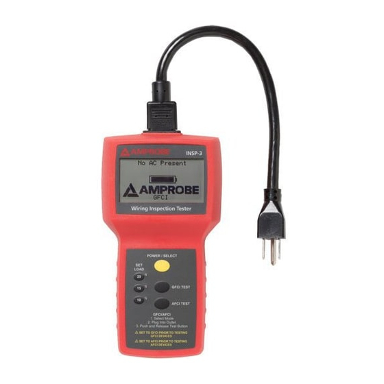
- Page 5 INSP-3 Wiring Inspection Tester 1) Power Cord Receptacle 8) 20A load push button selector 2) Power/Select Push button 9) 15A load LED indicator 3) GFCI Test Push button 10) 15A load push button 4) AFCI Test Push button selector 5) Battery Compartment...
-
Page 6: Table Of Contents
CONTENTS SYMBOLS ................ 2 UNPACKING AND INSPECTION ........4 INTRODUCTION .............. 4 Features ..............4 OPERATION ..............6 Main Screen (Refer to Fig.2) ........6 Secondary Screen (Refer to Fig.3) ......7 What the Readings Mean ......... 8 SPECIFICATION ............. 11 MAINTENANCE AND REPAIR ........ -
Page 7: Symbols
Audible tone Canadian and US.] Safety Information • The INSP-3 wiring inspection Tester is conformed to EN61010-1:2001; CAT II 120 V, class II and pollution deg.2 • Do not exceed the maximum overload limits (see specifications) nor the limits marked on the instrument itself. - Page 8 • Inspect the INSP-3 wiring inspection tester before every use. Do not use any damaged part. • Never ground yourself when taking measurements.
-
Page 9: Unpacking And Inspection
INTRODUCTION The INSP-3, wiring inspector is a rugged tester designed to verify building wiring compliance to electrical code, especially voltage drop under load. Identify issues with splices, connections and conductor quality, crucial to safety and performance of the electrical system. - Page 10 • Meter detects faulty wiring in need of repair without removing outlets cover plates, or panel covers: • Faulty splices and connections • Incorrect wiring • Undersized wiring • Faulty GFCIs, • Faulty or incorrectly wired AFCIs • Incorrect line voltage • Poor ground quality • User selectable 10,15 and 20 amps loads to verify performance of the electrical system • Incorrect wiring or voltage drop test failure is clearly indicated by flashing screen • Will not trip circuit breakers or blow fuses during the test • Tests GFCI and AFCI operations • Check ground quality for safety and ability to...
-
Page 11: Operation
Ground impedance and polarity is not tested on 2 wire outlets. 1. Push GFCI TEST push button or AFCI TEST push button before plugging the INSP-3 to a GFCI or AFCI circuit outlet to be tested. 2. Plug the INSP-3 wiring inspection tester into an energized 120V wall outlet using the power cord provided. -
Page 12: Secondary Screen (Refer To Fig.3)
Line 2: shows the polarity status Line 3: The “SET LOAD” switch is set for a test drawing 15 amps. At 15 amps of current draw, the voltage at the outlet would drop by 4.2%. Since 4.2% is lower than the NEC recommendation of a maximum of 5% drop, it would not be flashing. -
Page 13: What The Readings Mean
the wiring resistance would limit the current to approximately 424 Amps. Line 5: shows that if the hot and ground conductors were to be shorted at the outlet, the wiring resistance would limit the current to approximately 850 Amps. NOTE: Unit turns on automatically when plugged in. - Page 14 loose connection or if the wiring run is too long or has too small a gauge wire for the length of the run. The electrical code states that “. . . where the maximum voltage drop on both feeders and branch circuits to the farthest outlet does not exceed 5 percent, will provide reasonably efficiency of operation”...
- Page 15 and high technology electronics are reliant on a good quality equipment ground for proper operation. A typical rule of thumb is ground resistance in most cases should be less than 2 ohms. Loose connection, splices or too small of a ground conductor can cause high impedance.
-
Page 16: Specification
smaller than 14 gauge wire and not longer than 4 feet. Large power disturbances or spikes may cause erratic readings. SPECIFICATION Load: Constant 0, 10,15 or 20 AMP simulation regardless of line voltage Operating Voltage: 95-140V AC Power: 9V Alkaline Battery Fuse: ½... -
Page 17: Battery Replacement
3. Review the operating instructions for possible mistakes in operating procedure. Except for the replacement of the battery, repair of the meter should be performed only by a Factory Authorized Service Center or by other qualified instrument service personnel. The front panel and case can be cleaned with a mild solution of detergent and water. - Page 18 60 Hz 121.5 Vrms Polarity OK Volt Drop @15A=4.2% (1.1% Hot + 3.1% Neut) Loaded Voltage =116.4 Gnd Impedance = .27e Fig.2 121.5 Vrms 60 Hz Polarity OK Common Mode: 0.79V HotNeu Fault: 424A HotGnd Fault: 850A Fig.3 Fig.1...
- Page 19 121.5V Drop@15A=3.9% (1.5% Hot + 2.4% Neut) Loaded Voltage=118.0 Push GFCI to trip GFCI Breaker Test Testing at 6mA GFCI Breaker Test GFCI Breaker Test GFCI Test passed at Failed 6mA Test 6mA in 1.2 Seconds Testing at 30mA GFCI Breaker Test GFCI Breaker Test Failed 6mA Test GFCI Test passed at...
Need help?
Do you have a question about the INSP-3 and is the answer not in the manual?
Questions and answers